Table of Contents
Advertisement
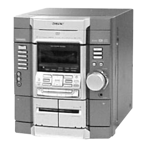
HCD-RV600D/RV600DJ
SERVICE MANUAL
Ver 1.2 2003. 10
• HCD-RV600D/RV600DJ is the tuner,
deck, DVD and amplifier section in
MHC-RV600D/RV600DJ.
This system incorporates Dolby* Digital, Pro Logic
Surround, DTS**, and the DTS Digital Surround
System.
* Manufactured under license from Dolby
Laboratories.
"Dolby", "Pro Logic", and the double-D symbol
are trademarks of Dolby Laboratories.
** Manufactured under license from Digital Theater
Systems, Inc. "DTS" and "DTS Digital Surround"
are registered trademarks of Digital Theater
Systems, Inc.
Amplifier section
The following measured at AC 120, 127, 220, 240 V,
50/60 Hz
DIN power output (rated) 100 + 100 watts (6 ohms
at 1 kHz, DIN)
Continuous RMS power output (reference)
100 + 100 watts (6 ohms
at 1 kHz, 10% THD)
Inputs
MD/VIDEO (AUDIO) IN (phono jacks):
voltage 450/250 mV,
impedance 47 kilohms
GAME (AUDIO) IN (phono jack):
voltage 250 mV,
impedance 47 kilohms
MIC (phone jack) (except for North American and
European models):
sensitivity 1 mV,
impedance 10 kilohms
Outputs
MD/VIDEO (AUDIO OUT) (phono jacks):
voltage 250 mV,
impedance 1 kilohm
VIDEO OUT (phono jack):
max. output level
1 Vp-p, unbalanced, Sync
negative, load impedance
75 ohms
S-VIDEO OUT (4-pin/mini-DIN jack):
Y: 1 Vp-p, unbalanced,
Sync negative,
C: 0.286 Vp-p,
load impedance 75 ohms
Sony Corporation
9-874-120-03
2003J16-1
Home Audio Company
© 2003.10
Published by Sony Engineering Corporation
Photo : HCD-RV600D
Model Name Using Similar Mechanism
DVD
DVD Mechanism Type
Section
Base Unit Name
Model Name Using Similar Mechanism
Tape deck
Section
Tape Transport Mechanism Type
SPECIFICATIONS
COMPONENT VIDEO OUT:
Y: 1 Vp-p, 75 ohms
P
, P
: 0.7 Vp-p, 75 ohms
B
R
PHONES (stereo mini jack):
accepts headphones of
8 ohms or more
Front speaker:
accepts impedance of 6 to
16 ohms
SUB WOOFER OUT
voltage 1 V,
impedance 1 kilohm
Disc player section
System
Compact disc and digital
audio and video system
Laser
Semiconductor laser
(DVD: λ=650 nm,
CD: λ=780 nm)
Emission duration:
continuous
Wavelength
780 – 790 nm
Frequency response
DVD (PCM 48 kHz):
2 Hz – 22 kHz (±1 dB)
CD: 2 Hz – 20 kHz
(±1 dB)
MINI HI-FI COMPONENT SYSTEM
E Model
NEW
CDM58D-DVBU17
DVBU17
NEW
CWM43RR-01
Video color system format
NTSC, PAL
CD OPTICAL DIGITAL OUT
(Square optical connector jack, rear panel)
Wavelength
660 nm
Output Level
–18 dBm
Tape deck section
Recording system
4-track 2-channel stereo
Frequency response
40 – 13,000 Hz (±3 dB),
using Sony TYPE I
cassette
Tuner section
FM stereo, FM/AM superheterodyne tuner
FM tuner section
Tuning range
87.5 – 108.0 MHz
Antenna
FM lead antenna
Antenna terminals
75 ohm unbalanced
Intermediate frequency
10.7 MHz
— Continued on next page —
Advertisement
Table of Contents

Related Manuals for Sony HCD-RV600D


Summary of Contents for Sony HCD-RV600D
- Page 1 HCD-RV600D/RV600DJ SERVICE MANUAL E Model Ver 1.2 2003. 10 • HCD-RV600D/RV600DJ is the tuner, deck, DVD and amplifier section in MHC-RV600D/RV600DJ. Photo : HCD-RV600D This system incorporates Dolby* Digital, Pro Logic Model Name Using Similar Mechanism Surround, DTS**, and the DTS Digital Surround...
-
Page 2: Model Identification
(XX is a number) system has performed the self- 0.4 watts (in Power diagnosis function. Saving Mode) , Contact your nearest Sony Approx. 280 × 325 × dealer or local authorized Sony Dimensions (w/h/d) service facility and give the 368 mm 5-character service number. -
Page 3: Table Of Contents
MARK 0 ON THE SCHEMATIC DIAGRAMS AND IN THE PARTS 7-4. DVD Mechanism Deck Section LIST ARE CRITICAL TO SAFE OPERATION. REPLACE THESE (CDM58D-DVBU17) ················································· 68 COMPONENTS WITH SONY PARTS WHOSE PART NUMBERS APPEAR AS SHOWN IN THIS MANUAL OR IN SUPPLEMENTS 8. ELECTRICAL PARTS LIST ······································· 69... -
Page 4: General
HCD-RV600D/RV600DJ Ver 1.1 2002.11 Note for Service: [DISC TRAY LOCK] Releasing Procedure : The disc tray lock function for the antitheft of a demonstration disc 1. Press two buttons of x and Z simultaneously for five seconds. in the store is equipped. -
Page 5: Remote Control
HCD-RV600D/RV600DJ Remote control Inserting two R6 (size AA) batteries into the remote N – Z ALPHABETICAL ORDER NEXT eh (18, 27) A – M Number buttons qs (19, 27, 39, ALBUM +/– wd wl (19, 20, 26) 40, 42, 49) -
Page 6: Disassembly
HCD-RV600D/RV600DJ SECTION 2 DISASSEMBLY • The equipment can be removed using the following procedure. CASE (TOP) DVD LID FRONT PANEL SECTION TAPE MECHANISM DECK DVD MECHANISM DECK BLOCK (CWM43RR-01) SUB TRANSFORMER BOARD, PANEL BOARD, SUB PANEL BOARD, VIDEO BOARD, MB BOARD... -
Page 7: Case (Top)
HCD-RV600D/RV600DJ Note: Follow the disassembly procedure in the numerical order given. 3 seven screws (BVTP 3 × 8) 4 case 2-1. Case (Top) 2 three screws (case 3 TP2) 1 three screws (case 3 TP2) 2-2. Lid (DVD) DVD mechanism deck (CDM58D-DVBU17) 1 Turn the pulley to the direction of arrow. -
Page 8: Front Panel Section
HCD-RV600D/RV600DJ front panel section screw (BVTP 3 × 8) connector (CN502) screw (BVTP 3 × 8) chassis section connector (CN603) connector (CN602) flat type wire (CN605) three screws (BVTP 3 × 8) -
Page 9: Optical Pick-Up
HCD-RV600D/RV600DJ 2-13. Optical Pick-up 3 step screw (L) 4 step screw (L) insulator insulator 9 optical pick-up 5 step screw (L) insulator 1 floating screw (PTPWH M2.6) 0 holder (DBU1) assy 2-14. MOTOR Board, DIODE Board, SENSOR Board screw (PTPWH 2.6 × 8) -
Page 10: Test Mode
HCD-RV600D/RV600DJ Ver 1.1 2002.11 SECTION 3 TEST MODE [Cold Reset] [GC Test Mode] • The cold reset clears all data including preset data stored in the • This mode is used to check the FL tube, LED, keyboard, vol- RAM to initial conditions. Execute this mode when returning ume and phones. - Page 11 HCD-RV600D/RV600DJ [MC Test Mode] [Aging Mode] • This mode is used to check operations of the respective sections This mode can for operation check of tape deck section. of Amplifier, Tuner, and Tape. • If an error occurred: Procedure: The aging operation stops and display then status.
- Page 12 HCD-RV600D/RV600DJ [DVD Service Mode] 2. CDM Error History <CDM58D Error History Display> • The sequence during the aging mode is following as below. 11 digits are displayed after the M character. Aging mode sequence (DVD section): Example of display : M0FF400220000...
-
Page 13: Mechanical Adjustments
HCD-RV600D/RV600DJ SECTION 4 MECHANICAL ADJUSTMENTS [REPEAT 5 LIMIT OFF MODE] Precaution • This mode is used to enable infinite repetitions. 1. Clean the following parts with a denatured alcohol-moistened Normally, the number of repetitions allowed is 5. swab: Procedure: record/playback heads pinch rollers 1. -
Page 14: Electrical Adjustments
HCD-RV600D/RV600DJ SECTION 5 ELECTRICAL ADJUSTMENTS 2. Turn the adjustment screw and check output peaks. If the peaks DECK SECTION 0 dB=0.775 V do not match for L-CH and R-CH, turn the adjustment screw so that outputs match within 1dB of peak. - Page 15 HCD-RV600D/RV600DJ TUNER SECTION FM Tuned Level Adjustment FM RF SSG 75 Ω coaxial Carrier frequency : 98 MHz Modulation : AUDIO 1 kHz, 75 kHz FM ANTENNA terminal deviation (100%) (TM1) : 25 dB (at 75 Ω open) Output level Procedure: Supply a 25 dB 98 MHz signal from the ANTENNA terminal.
-
Page 16: Diagrams
HCD-RV600D/RV600DJ SECTION 6 Ver 1.2 2003.10 DIAGRAMS 6-1. Block Diagrams – DVD DSP Section – DOUT OPTICAL PICK-UP IC509 BLOCK IC001 LRCK CD DECODER (KHM-240AAA) DVD/CD RF AMP SERVO DSP PCMD IC206 DVDRFP RFAC 50 RFAC DOUT IC701 DVD SYSTEM PROCESSOR... -
Page 17: Dvd Sys Section
HCD-RV600D/RV600DJ – DVD SYS Section – IC1001 IC1104(3/3) DISPLAY CONTROL MASTER CONTROL Q1004-1008 D1001-1005 S1002-1014 S1062 Q1010-1012 D1007-1009 FUNCTION DISPLAY 22 KEY0 ENTER 73 DISPLAY KEY S1061 Q1009 GAME-MIXING S1022-1034 GAME-LED POWER POWER KEY POWER DRIVER FUNCTION MD/VIDEO KEY1 DRIVER... -
Page 18: Tuner Section
HCD-RV600D/RV600DJ – Tuner Section – AM/FM IF MPX IC11 RF IF L-CH MAIN L OUT FM IF SECTION (Page 24) FM TUNED R OUT R-CH LEVEL A+12V A+12V AM IF IN (FE2,3) MASTER CONTROL IFT11 RV11 IC1104(1/3) IC51 AM MIX OUT... -
Page 19: Main Section
HCD-RV600D/RV600DJ Ver 1.2 2003.10 – Main Section – Q110 MREQ • RCH is omitted due to same as LCH • Signal Path IC301 D/A CONVERTER : FM : DVD 13 DATA 14 CLK : DIGITAL OUT 15 LAT : PB(DECK A) -
Page 20: Circuit Boards Location
HCD-RV600D/RV600DJ 6-2. Circuit Boards Location THIS NOTE IS COMMON FOR PRINTED WIRING BOARDS AND SCHEMATIC DIAGRAMS. (In addition to this, the necessary note is printed in each block.) Note on Schematic Diagram: Note on Printed Wiring Boards: • All capacitors are in µF unless otherwise noted. pF: µµF •... -
Page 21: Printed Wiring Board - Rf Board
HCD-RV600D/RV600DJ 6-3. Printed Wiring Board – RF Board – • See page 25 for Circuit Boards Location. -
Page 22: Schematic Diagram - Rf Board
HCD-RV600D/RV600DJ 6-4. Schematic Diagram – RF Board – • See page 53 for Wavefoms. • See page 62 for IC Block Diagrams. CN002 C027 C031 R026 R023 1000p JL005 C030 C025 R025 C029 JL004 CN001 C013 R024 JL007 C006 C008... -
Page 23: Printed Wiring Board - Mb Board (Side B)
HCD-RV600D/RV600DJ Ver 1.2 2003.10 6-6. Printed Wiring Board – MB Board (Side B) – • See page 25 for Circuit Boards Location. IC706 IC703 IC501 IC503 • Semiconductor Location Ref. No. Location IC903 IC907 Q 9 0 1 D901 IC202... - Page 24 HCD-RV600D/RV600DJ Ver 1.2 2003.10 6-7. Schematic Diagram – MB Board (1/6) – • See page 56 for IC Pin Function Description. IC703(2/2) NJM3404AM-TE2 TP701 R544 100k C523 R550 R545 100k R540 1500p IC706 MSM51V18165F -60TSKR1 TP703 C715 FL706 R700 R541 0.0015...
-
Page 25: Schematic Diagram - Mb Board (1/6)
HCD-RV600D/RV600DJ Ver 1.2 2003.10 6-8. Schematic Diagram – MB Board (2/6) – • See page 59 for IC Pin Function Description. • See page 53 for Wavefoms. R729 FL901 R805 C901 POWER-EMIS 100 4V C906 0.01 F C902 0.01 R901... - Page 26 HCD-RV600D/RV600DJ Ver 1.2 2003.10 6-9. Schematic Diagram – MB Board (3/6) – CN202 JL209 JL208 JL207 R267 JL206 JL212 R268 R270 R271 JL205 C202 C216 C201 C205 C218 JL204 R277 R278 R279 R280 R281 JL203 R262 R263 R264 R265 R266...
-
Page 27: Schematic Diagram - Mb Board (2/6)
HCD-RV600D/RV600DJ Ver 1.2 2003.10 6-10. Schematic Diagram – MB Board (4/6) – IC202 MT48LC4M32B2-7 C217 0.01 C219 0.01 C226 0.01 C234 0.01 C238 0.01 C239 0.01 R251 C242 0.01 C244 0.01 C245 0.01 C248 0.01 C249 0.01 C253 0.01 C254... - Page 28 HCD-RV600D/RV600DJ Ver 1.2 2003.10 6-11. Schematic Diagram – MB Board (5/6) – • See page 61 for IC Block Diagrams. IC301 PCM1748 C305 R315 R326 FL302 C302 0.01 C303 JW307 C308 R307 D301 0.01 1SS355TE C307 6.3V FL303 R324 R323...
-
Page 29: Schematic Diagram - Mb Board (3/6)
HCD-RV600D/RV600DJ 6-12. Schematic Diagram – MB Board (6/6) – • See page 61 for IC Block Diagrams. CL505 MNT0 CL504 MNT1 R587 CL503 MNT2 CL502 MNT3 CL501 FL502 C567 PWR-EMIS R569 C522 C568 R537 R536 R670 R671 CN501 29P TO RFAMP... -
Page 30: Printed Wiring Board – Tc Board
HCD-RV600D/RV600DJ 6-13. Printed Wiring Board – TC Board – • See page 25 for Circuit Boards Location. • Semiconductor Location Ref. No. Location IC303 IC601 IC601 Q601 Q602 Q603 Q604 Q605 Q606 Q607 Q608 Q609 Q610 Q611 (Page 38) (Page 38) -
Page 31: Schematic Diagram - Mb Board (4/6)
HCD-RV600D/RV600DJ 6-14. Schematic Diagram – TC Board – C657 C624 R627 C621 C620 R622 C662 0.01 C617 R621 C626 47 16V CN602 R620 C615 C627 1 50V R618 IC601 HA12237F R617 CN603 4.7k R616 4.7k R615 4.7k CN608 C630 Q606... -
Page 32: Printed Wiring Board - Main Section
HCD-RV600D/RV600DJ 6-15. Printed Wiring Board – Main Section – • See page 25 for Circuit Boards Location. (Page 42) (Page 28) (Page 42) (Page 49) (Page 28) IC51 IC1104 IC703 IC11 (Page 46) IC706 IC102 IC704 IC101 (Page 36) (Page 36) -
Page 33: Schematic Diagram – Main Section (1/3)
HCD-RV600D/RV600DJ 6-16. Schematic Diagram – Main Section (1/3) – • See page 64 for IC Block Diagrams. • See page 53 for Wavefoms. JR10 0.01 F JR12 0.01 BN1A4M 2SC1674 JR19 JR15 47000p 220k 3.3k RB41 2SC2603TP IC11 DA204K LA1845... -
Page 34: Schematic Diagram – Main Section (2/3)
HCD-RV600D/RV600DJ 6-17. Schematic Diagram – Main Section (2/3) – Q102 C106 2SC3623ATP C172 R109 C104 R147 100p R106 J101 100k R107 Q152 4.7k 2SC3623ATP C155 R156 100p C157 100k R157 C161 C162 R176 0.0047 4.7k R151 R154 C180 100k 2.2k... -
Page 35: Schematic Diagram – Main Section (3/3)
HCD-RV600D/RV600DJ 6-18. Schematic Diagram – Main Section (3/3) – • See page 54 for IC Pin Function Description. • See page 53 for Wavefoms. Q720 Q721 BN1F4M BN1F4M D735 R755 CN708 1SS355TE J102 C791 C739 R125 R753 100k R763 R769 R766 6.8k... -
Page 36: Printed Wiring Board - Video Board
HCD-RV600D/RV600DJ Ver 1.2 2003.10 6-19. Printed Wiring Board – VIDEO Board – • See page 25 for Circuit Boards Location. • Semiconductor Location Ref. No. Location D502 D503 D504 D505 D506 IC505 D507 D508 D509 D510 D511 D512 D513 D514... -
Page 37: Schematic Diagram – Video Board
HCD-RV600D/RV600DJ Ver 1.2 2003.10 6-20. Schematic Diagram – VIDEO Board – • See page 63 for IC Block Diagrams. Q109 C506 2SC3623 R186 2.2k IC505(1/2) NJM2100M C553 0.0047 R188 2.2k R509 C505 100k JW515 R187 R532 R531 R530 CN507 C552 2.2k... -
Page 38: Printed Wiring Board - Front Amp Board
HCD-RV600D/RV600DJ 6-21. Printed Wiring Board – FRONT AMP Board – • See page 25 for Circuit Boards Location. IC922 IC932 IC921 IC923 IC934 IC201 (Page 50) (Page 38) (Page 38) • Semiconductor Location Ref. No. Location Ref. No. Location Ref. No. Location... -
Page 39: Schematic Diagram - Front Amp Board
HCD-RV600D/RV600DJ 6-22. Schematic Diagram – FRONT AMP Board – IC201 STK402-100S IC932 CN271 D271 D5SBA204101 C271 100V C273 2200 IC934 TA7805S C272 100V IC923 TA7812S C274 JW933 2200 R205 0.22 TM201 R211 100 1/4W FR RY281 L281 IC922 TA7809S C206 R206 0.068... -
Page 40: Printed Wiring Board - Panel Section
HCD-RV600D/RV600DJ 6-23. Printed Wiring Board – Panel Section – • See page 25 for Circuit Boards Location. IC1003 • Semiconductor Location Ref. No. Location D1002 D1003 D1004 D1005 D1006 D1007 IC1001 D1008 D1010 D1102 20 21 IC1002 D1103 D1151 D1201... -
Page 41: Schematic Diagram - Panel Section (1/2)
HCD-RV600D/RV600DJ 6-24. Schematic Diagram – Panel Section (1/2) – • See page 53 for Wavefoms. Q1003 Q1002 Q1001 CN1001 BA1L3Z BA1L3Z BA1L3Z FL1001 AMP-L JW1007 JW1008 JW1009 JW1010 R1080 100k R1079 R1078 100k 100k J1001 R1015 C1035 FB1003 100p C1156... -
Page 42: Schematic Diagram - Panel Section (2/2)
HCD-RV600D/RV600DJ 6-25. Schematic Diagram – Panel Section (2/2) – R1009 R1010 R1011 R1012 R1013 R1014 4.7k 6.8k SURROUND R1022 R1023 R1024 R1025 R1026 R1027 R1028 R1029 R1030 R1031 R1032 R1033 R1034 1.5k 1.5k 2.2k 3.3k 4.7k 6.8k R1050 R1051 R1052... -
Page 43: Schematic Diagram - Sensor Section
HCD-RV600D/RV600DJ 6-26. Schematic Diagram – Sensor Section – • See page 63 for IC Block Diagrams. IC B/D 6-27. Printed Wiring Board – Sensor Section – • See page 25 for Circuit Boards Location. SENSOR BOARD MOTOR BOARD DRIVER BOARD... -
Page 44: Printed Wiring Board - Transformer Board
HCD-RV600D/RV600DJ 6-28. Printed Wiring Board – TRANSFORMER Board – • See page 25 for Circuit Boards Location. (Page 38) (Page 52) (Page 52) (Page 44) -
Page 45: Schematic Diagram - Transformer Board
HCD-RV600D/RV600DJ 6-29. Schematic Diagram – TRANSFORMER Board – T911 F914 CN911 6.3A CN915 JW923 F915 6.3A F918 6.3A CN914 F919 R917 C929 1 50V C930 1 50V D913 D911 RD4.7F-T7B1 11ES2-NTA2B Q971 2SA1932 C913 R911 0.68 R913 C911 1/4W R914... -
Page 46: Printed Wiring Board - Sub Transformer Board
HCD-RV600D/RV600DJ 6-30. Printed Wiring Board – SUB TRANSFORMER Board – • See page 25 for Circuit Boards Location. (Page 50) • Semiconductor Location Ref. No. Location D901 D902 D903 D904 D905 IC901 Q901 (Page 50) -
Page 47: Schematic Diagram - Sub Transformer Board
HCD-RV600D/RV600DJ 6-31. Schematic Diagram – SUB TRANSFORMER Board – • Waveforms – MB Board – – VIDEO Board – – RF Board – – MAIN Board – IC906 8 XTO IC503 ed C-OUT IC001 1 DVD RFP IC1104 qa SUB, CLOCK-OUT 2.9Vp-p... -
Page 48: Ic Pin Function Descriptions
HCD-RV600D/RV600DJ 6-32. IC Pin Function Descriptions • IC1104 M30620MCN-A04FP (MAIN Board) Pin No. Pin Name Description Pin No. Pin Name Description S-OUT SERIAL OUT CLOSE CLOSE SW S-CLK SERIAL CLOCK UP/DOWN SW BU UP/DOWN SW POWER-LED STANDBY-LED ON(L)/OFF(H) T-SENS TABLE SENSOR... - Page 49 HCD-RV600D/RV600DJ Pin No. Pin Name Description VACS-IN VACS IN AVSS — NO-USE — Not used V.REF — AV Referense AVCC — AVCC S-IN SERIAL IN...
- Page 50 HCD-RV600D/RV600DJ • IC701 CXD1882R (MB Board) Pin No. Pin Name Description 1, 2 D5, D6 Two-way data bus with the mechanism controller — Ground terminal (digital system) Two-way data bus with the mechanism controller Address signal input from the mechanism controller —...
- Page 51 HCD-RV600D/RV600DJ Pin No. Pin Name Description XPDI Not used VDDS — Power supply terminal (+5V) (digital system) 59, 60 HA0, HA2 Not used — Ground terminal (digital system) 62, 63 HCS0, HCS1 Not used — Power supply terminal (+3.3V) (digital system)
- Page 52 HCD-RV600D/RV600DJ Pin No. Pin Name Description 128, 129 VCCA3, VCCA2 — Power supply terminal (+3.3V) (analog system) Signal output from the charge pump for phase comparator PDHVCC Middle point voltage input terminal for RF PLL Signal output from the charge pump for frequency comparator...
- Page 53 HCD-RV600D/RV600DJ • IC901 CXP973064-220R (MB Board) Pin No. Pin Name Description EEP SO Not used SDEN Serial data enable signal output to DVD/CD RF amplifier DOCTRL/ Digital out on/off control signal output to the digital signal processor ISBTEST “L”: digital out off, “H”: digital out on...
- Page 54 HCD-RV600D/RV600DJ Pin No. Pin Name Description TRAY OUT Disc tray out detection signal input terminal Not used GFS DVD Guard frame sync signal input from the DVD decoder MUTE CD Muting on/off control signal output to the digital signal processor “H”: muting on MUTE 2D Muting on/off control signal output to the motor/coil driver “H”: muting on...
- Page 55 HCD-RV600D/RV600DJ Ver 1.2 2003.10 • IC Block Diagrams – MB Board – IC509 CXD3068Q...
- Page 56 HCD-RV600D/RV600DJ – RF Board – IC001 CXD1881AR 64 63 62 61 60 59 55 54 53 52 FAST ATTACK INPUT OUTPUT HOLD FULL WAVE AGC CHARGE INHIBIT RECTIFER PUMP PROGRAMMABLE FROM S-PORT INPUT EQUALIZER DVDRFP FILTER BIAS DVDRFN DIFFERENTIATOR INPUT...
- Page 57 HCD-RV600D/RV600DJ – VIDEO Board – IC502 NJM2244M-TE2 VIN1 75 Ω VOUT DRIVER VIN2 BIAS VIN3 (MUTE) IC503 MM1568 VCC2 VCC1 BIAS 75Ω COUT DRIVER MUTE1 CLAMP GND2 75Ω VOUT DRIVER YC MIX VSAG CLAMP GND2 75Ω YOUT DRIVER BIAS BIAS...
-
Page 58: Main Board
HCD-RV600D/RV600DJ – MAIN Board – IC11 LA1845 PF.AMP DEOODER PILOT BUFF ANTI-BIRDIE CANCEL P-DET STEREO ø LEVEL AM/FM COMP S-CURVE BUFF PILOT π 304kHz 19k 0 TUNING DRIVE IC51 LC72121... -
Page 59: Exploded Views
HCD-RV600D/RV600DJ SECTION 7 EXPLODED VIEWS NOTE: • -XX, -X mean standardized parts, so they may • Abbreviation The components identified by mark 0 or have some differences from the original one. : 240V AC Area in E model dotted line with mark 0 are critical for safety. -
Page 60: Front Panel Section
4-231-836-01 SPRING (HEART CAM-A) 4-238-628-01 MIC KNOB 4-231-841-01 SPRING (HEART CAM-B) A-4676-685-A MICROPHONE BOARD, COMPLETE 4-963-404-22 EMBLEM (5-A), SONY FL1001 1-518-820-11 INDICATOR TUBE, FLUORESCENT 4-240-174-11 HOLDER, FL TUBE The components identified by mark 0 or dotted line with mark 0 are critical for safety. -
Page 61: Chassis Section
HCD-RV600D/RV600DJ 7-3. Chassis Section not supplied not supplied not supplied not supplied not supplied not supplied F919 F918 F915 not supplied F914 not supplied T911 not supplied Ref. No. Part No. Description Remarks Ref. No. Part No. Description Remarks A-4676-691-A TRANSFORMER BOARD, COMPLETE... -
Page 62: Dvd Mechanism Deck Section
HCD-RV600D/RV600DJ 7-4. DVD Mechanism Deck Section (CDM58D-DVBU17) supplied Ref. No. Part No. Description Remarks Ref. No. Part No. Description Remarks 4-218-254-21 SCREW (M2.6) +PTPWH X-4954-450-1 PULLEY (240) ASSY 4-231-187-01 CAM (RELAY) 4-985-672-01 SCREW (+PTPWH M2.6), FLOATING X-4954-616-1 LEVER (CHANGE 2) ASSY... -
Page 63: Electrical Parts List
HCD-RV600D/RV600DJ SECTION 8 DIODE DRIVER ELECTRICAL PARTS LIST FRONT AMP NOTE: • Due to standardization, replacements in the • RESISTORS • SEMICONDUCTORS In each case, u: µ, for example: parts list may be different from the parts All resistors are in ohms. - Page 64 HCD-RV600D/RV600DJ FRONT AMP Ref. No. Part No. Description Remarks Ref. No. Part No. Description Remarks D291 8-719-991-33 DIODE 1SS133T-77 R228 1-249-435-11 CARBON 1/4W < IC > R230 1-249-425-11 CARBON 4.7K 1/4W F R231 1-249-425-11 CARBON 4.7K 1/4W F IC201 8-749-016-95 IC STK402-100S...
- Page 65 HCD-RV600D/RV600DJ MAIN Ref. No. Part No. Description Remarks Ref. No. Part No. Description Remarks A-4730-809-A MAIN BOARD, COMPLETE (RV600DJ) 1-162-974-11 CERAMIC CHIP 0.01uF 1-164-159-21 CERAMIC 0.1uF ****************************** A-4730-808-A MAIN BOARD, COMPLETE (RV600D:TH) C101 1-126-382-11 ELECT 100uF 20.00% 10V ******************************** A-4729-735-A MAIN BOARD, COMPLETE (RV600D:EA)
- Page 66 HCD-RV600D/RV600DJ MAIN Ref. No. Part No. Description Remarks Ref. No. Part No. Description Remarks C165 1-136-169-00 FILM 0.22uF 5.00% 50V C826 1-164-159-21 CERAMIC 0.1uF C166 1-126-795-11 ELECT 10uF 20.00% 50V C827 1-164-159-21 CERAMIC 0.1uF C167 1-164-156-11 CERAMIC CHIP 0.1uF C828 1-164-159-21 CERAMIC 0.1uF...
- Page 67 HCD-RV600D/RV600DJ MAIN Ref. No. Part No. Description Remarks Ref. No. Part No. Description Remarks D729 8-719-085-36 DIODE 11EQS04-TB5 JR19 1-216-864-11 METAL CHIP 1/16W D730 8-719-988-61 DIODE 1SS355TE-17 JR104 1-216-864-11 METAL CHIP 1/10W D731 8-719-988-61 DIODE 1SS355TE-17 JR181 1-216-864-11 METAL CHIP...
- Page 68 HCD-RV600D/RV600DJ MAIN Ref. No. Part No. Description Remarks Ref. No. Part No. Description Remarks Q720 8-729-900-63 TRANSISTOR BN1F4M-TP R110 1-216-841-11 METAL CHIP 1/16W Q721 8-729-900-63 TRANSISTOR BN1F4M-TP R111 1-216-833-11 METAL CHIP 1/16W < RESISTOR > R112 1-216-833-11 METAL CHIP 1/10W...
- Page 69 HCD-RV600D/RV600DJ MAIN Ref. No. Part No. Description Remarks Ref. No. Part No. Description Remarks R190 1-216-845-11 METAL CHIP 100K 1/10W R808 1-216-809-11 METAL CHIP 1/16W R809 1-216-851-11 METAL CHIP 330K 1/16W R675 1-216-833-11 METAL CHIP 1/16W R810 1-216-864-11 METAL CHIP...
- Page 70 HCD-RV600D/RV600DJ MAIN Ref. No. Part No. Description Remarks Ref. No. Part No. Description Remarks R879 1-216-809-11 METAL CHIP 1/16W C202 1-218-990-11 SHORT CHIP C203 1-164-947-11 CERAMIC CHIP 0.01uF R880 1-216-809-11 METAL CHIP 1/16W C204 1-164-947-11 CERAMIC CHIP 0.01uF R881 1-216-809-11 METAL CHIP...
- Page 71 HCD-RV600D/RV600DJ Ver 1.2 2003.10 Ref. No. Part No. Description Remarks Ref. No. Part No. Description Remarks C274 1-164-947-11 CERAMIC CHIP 0.01uF C568 1-117-370-11 CERAMIC CHIP 10uF C569 1-107-820-11 CERAMIC CHIP 0.1uF C302 1-164-947-11 CERAMIC CHIP 0.01uF C570 1-117-370-11 CERAMIC CHIP...
- Page 72 HCD-RV600D/RV600DJ Ver 1.2 2003.10 Ref. No. Part No. Description Remarks Ref. No. Part No. Description Remarks C777 1-107-820-11 CERAMIC CHIP 0.1uF FL704 1-234-177-21 FERRITE FL705 1-234-177-21 FERRITE C778 1-107-820-11 CERAMIC CHIP 0.1uF FL706 1-234-177-21 FERRITE C779 1-117-370-11 CERAMIC CHIP 10uF...
- Page 73 HCD-RV600D/RV600DJ Ver 1.2 2003.10 Ref. No. Part No. Description Remarks Ref. No. Part No. Description Remarks R219 1-218-935-11 RES-CHIP 1/16W R284 1-218-953-11 RES-CHIP 1/16W R220 1-218-935-11 RES-CHIP 1/16W R285 1-218-953-11 RES-CHIP 1/16W R301 1-218-945-11 RES-CHIP 1/16W R221 1-218-935-11 RES-CHIP 1/16W...
- Page 74 HCD-RV600D/RV600DJ Ver 1.2 2003.10 Ref. No. Part No. Description Remarks Ref. No. Part No. Description Remarks R569 1-218-990-11 SHORT CHIP R710 1-218-965-11 RES-CHIP 1/16W R572 1-218-990-11 SHORT CHIP R711 1-218-957-11 RES-CHIP 2.2K 1/16W R712 1-218-965-11 RES-CHIP 1/16W R573 1-218-990-11 SHORT CHIP...
- Page 75 HCD-RV600D/RV600DJ Ver 1.2 2003.10 MICROPHONE MOTOR PANEL Ref. No. Part No. Description Remarks Ref. No. Part No. Description Remarks R799 1-218-990-11 SHORT CHIP R992 1-218-990-11 SHORT CHIP R805 1-218-990-11 SHORT CHIP R994 1-218-990-11 SHORT CHIP R824 1-218-990-11 SHORT CHIP R995...
- Page 76 HCD-RV600D/RV600DJ PANEL Ref. No. Part No. Description Remarks Ref. No. Part No. Description Remarks C1003 1-162-306-11 CERAMIC 0.01uF 30.00% 16V C1213 1-126-786-11 ELECT 47uF 20.00% 16V C1004 1-162-306-11 CERAMIC 0.01uF 30.00% 16V C1215 1-126-791-11 ELECT 10uF 20.00% 16V C1005 1-162-306-11 CERAMIC 0.01uF...
- Page 77 HCD-RV600D/RV600DJ PANEL Ref. No. Part No. Description Remarks Ref. No. Part No. Description Remarks D1151 8-719-911-19 DIODE 1SS133T-72 R1048 1-247-843-11 CARBON 3.3K 1/4W D1201 8-719-109-85 DIODE MTZJ-T-72-5.1B (EXCEPT E51,MX) R1049 1-249-425-11 CARBON 4.7K 1/4W F R1056 1-249-431-11 CARBON 1/4W D1204...
- Page 78 HCD-RV600D/RV600DJ PANEL REMOTE Ref. No. Part No. Description Remarks Ref. No. Part No. Description Remarks R1218 1-247-881-00 CARBON 120K 1/4W < DIODE > (EXCEPT E51,MX) R1219 1-249-433-11 CARBON 1/4W D728 8-719-085-36 DIODE 11EQS04-TB5 (EXCEPT E51,MX) R1220 1-249-433-11 CARBON 1/4W < IC >...
- Page 79 HCD-RV600D/RV600DJ SENSOR SUB PANEL Ref. No. Part No. Description Remarks Ref. No. Part No. Description Remarks C032 1-165-176-11 CERAMIC CHIP 0.047uF 10.00% 16V R025 1-216-809-11 METAL CHIP 1/16W C033 1-107-826-11 CERAMIC CHIP 0.1uF 10.00% 16V R026 1-218-718-11 METAL CHIP 0.5%...
- Page 80 HCD-RV600D/RV600DJ SUB PANEL SUB TRANSFORMER Ref. No. Part No. Description Remarks Ref. No. Part No. Description Remarks R1024 1-249-417-11 CARBON 1/4W F < CONNECTOR > R1025 1-249-419-11 CARBON 1.5K 1/4W F CN901 1-564-321-00 PIN, CONNECTOR (3.96MM PITCH) 2P R1026 1-249-419-11 CARBON 1.5K...
- Page 81 HCD-RV600D/RV600DJ TRANSFORMER Ref. No. Part No. Description Remarks Ref. No. Part No. Description Remarks C615 1-126-382-11 ELECT 100uF 20.00% 16V R601 1-249-426-11 CARBON 5.6K 1/4W C617 1-115-872-11 ELECT 2.2uF 20.00% 50V R602 1-249-426-11 CARBON 5.6K 1/4W R604 1-249-417-11 CARBON 1/4W F...
- Page 82 HCD-RV600D/RV600DJ TRANSFORMER VIDEO Ref. No. Part No. Description Remarks Ref. No. Part No. Description Remarks C913 1-126-968-11 ELECT 100uF 20.00% 50V C915 1-164-159-11 CERAMIC 0.1uF C530 1-104-665-11 ELECT 100uF 20.00% 10V C929 1-126-960-11 ELECT 20.00% 50V C531 1-128-551-11 ELECT 22uF 20.00% 25V...
- Page 83 HCD-RV600D/RV600DJ VIDEO Ref. No. Part No. Description Remarks Ref. No. Part No. Description Remarks EP502 1-537-771-21 TERMINAL BOARD, GROUND R528 1-249-419-11 CARBON 1.5K 1/4W F < FERRITE BEAD > R529 1-249-429-11 CARBON 1/4W R530 1-249-429-11 CARBON 1/4W FB513 1-412-473-21 INDUCTOR...
- Page 84 HCD-RV600D/RV600DJ REVISION HISTORY Clicking the version allows you to jump to the revised page. Also, clicking the version at the upper right on the revised page allows you to jump to the next revised page. Ver. Date Description of Revision 2002.09...