HP TouchSmart 9100 Maintenance And Service Manual
Business pc
Hide thumbs
Also See for TouchSmart 9100:
- User manual (72 pages) ,
- Quickspecs (14 pages) ,
- Application manual (37 pages)
Table of Contents
Advertisement
Advertisement
Table of Contents
Troubleshooting

Related Manuals for HP TouchSmart 9100


Summary of Contents for HP TouchSmart 9100
- Page 1 Maintenance and Service Guide HP TouchSmart 9100 Business PC...
- Page 2 Nothing herein should be construed as constituting an additional warranty. HP shall not be liable for technical or editorial errors or omissions contained herein. This document contains proprietary information that is protected by copyright.
-
Page 3: About This Book
About This Book WARNING! Text set off in this manner indicates that failure to follow directions could result in bodily harm or loss of life. CAUTION: Text set off in this manner indicates that failure to follow directions could result in damage to equipment or loss of information. - Page 4 About This Book...
-
Page 5: Table Of Contents
Keyboards and Mice ......................10 Misc Parts ..........................11 4 Removal and Replacement Procedures ................12 Preparing to disassemble the HP TouchSmart PC ................ 12 Synchronizing the wireless keyboard or mouse ................13 Hard drive/memory cover ....................... 14 I/O cover ..........................15 Feet ............................ - Page 6 Optical drive ......................... 26 Amp board shield ........................28 System board shield ....................... 28 Graphics card – Discrete or UMA .................... 29 WLAN module ........................31 TV tuner module ........................32 Fan – UMA graphics systems ....................34 System board ........................35 Processor ..........................
- Page 7 Starting system recovery from recovery discs .............. 65 Index ..........................67...
- Page 8 viii...
-
Page 9: Product Description
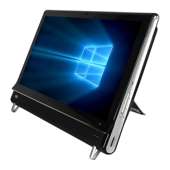
Product Description The HP TouchSmart 9100 Business PC transforms the PC experience with its All-in-One form factor and touch-enabled features. The PC can be used as an everyday desktop, but is better suited to reaching customers with interactive touch-enabled applications. -
Page 10: Components
Item Component LCD display optimized for State-of-the-art 58.4-cm (23-in) diagonal widescreen high-definition display with HP Touch BrightView technology.* HP BrightView technology improves the contrast and clarity of your display. In addition, it boasts a high resolution of 1920 x 1080 and a fast response time of 5 ms.**... - Page 11 Turn your HP TouchSmart 9100 Business PC on and open your HP TouchSmart TouchSmart button software. Or, if the computer is already turned on, press the button to open the HP TouchSmart software for quick access to your music, photos, videos, or the Web.
-
Page 12: Lower Left-Side Components
Read and play CD-ROM, DVD-ROM, CD Audio, DVD+/-R dual layer (DL), DVD- Video, and Video CD. B-CAS card slot (select Insert your B-CAS card (provided by HP), to decrypt high-definition television models only) signals. Lower left-side components... -
Page 13: Rear Components
Rear components Item Item Component DVI Video Out Provides digital video output for use with a second monitor or projector. IEEE 1394 port Provides connectivity to data storage devices and DV (digital video) cameras. USB 2.0 ports (3) Connect USB devices (USB 2.0) such as printers, external hard disk drives, digital cameras, and MP3 players. -
Page 14: Activity Led Indicator Lights
Stereo Audio In (TV tuner Connect audio for A/V input from a set-top box, digital video camera, or other models only) video device. IR emitter (blaster) (select Adhere to your TV set-top box IR receiver area to receive the remote control signal models only) while watching and recording TV programs. -
Page 15: Computer Stand
To assure that the computer is in a stable position on your desktop, pull the computer stand open until it snaps into place. Then, if you want to change the angle of the HP TouchSmart 9100, hold each side of the computer, and tilt it (the monitor moves forward; the stand stays in place) to an angle of between 5 degrees and 40 degrees from the vertical. -
Page 16: Spare Parts
Spare Parts See the following available spare parts for the HP TouchSmart PC. Processors and system board Description Spare Part Number Intel Core 2 Duo T9600 (2.80-GHz, 6-MB L2 cache) processor 613452-001 Intel Core 2 Duo P8700 (2.53-GHz, 3-MB L2 cache) processor 613454-001 Intel Core 2 Duo P7570 (2.26-GHz, 3-MB L2 cache) processor... -
Page 17: Memory
Memory Description Spare Part Number SODIMM, 4 GB, PC10600, DDR3-1333 593896-001 SODIMM, 2 GB, PC10600, DDR3-1333 593895-001 Misc Boards Description Spare Part Number TV tuner, PCIe x1 card, includes hardware kit 582726-001 GeForce GT230 1-GB PCIe graphics card 593888-001 DVI+1394 connector board 662720-001 802.11b/g/n WLAN PCIe adapter 593897-001... -
Page 18: Keyboards And Mice
Keyboards and Mice Description Spare Part Number Keyboard (blue, USB) For use in Brazil 596411-201 For use in the People's Republic of China 596411-AA1 For use in French Canada 596411-121 For use in Japan 596411-291 For use internationally 596411-371 For use in Latin America 596411-161 For use in Thailand 596411-281... -
Page 19: Misc Parts
Misc Parts Description Spare Part Number LCD display kit (includes inverter board and front bezel) 605166-001 Rear cover assembly 669261-001 Rear frame trim assembly kit Right 647992-001 Left 647991-001 Fan/blower 659243-001 Fan sink MXM graphics 659244-001 Integrated graphics 634467-001 Stand assembly 651741-001 Chin assembly 640295-001... -
Page 20: Removal And Replacement Procedures
Disconnect any external devices that are connected to the computer. Shut down the computer. After the system has completely shut down, disconnect the power adapter from the back of the HP TouchSmart PC. Remove the connector cover by inserting your finger under the gap on the bottom-left side of the cover and then pulling gently. -
Page 21: Synchronizing The Wireless Keyboard Or Mouse
You may need to manually synchronize the wireless keyboard or mouse if they are not functioning. To synchronize them: ● Make sure the keyboard and mouse are next to the HP TouchSmart PC, within 30 cm (1 foot) and away from interference from other devices. ●... -
Page 22: Hard Drive/Memory Cover
Hard drive/memory cover Prepare the computer for disassembly (see Preparing to disassemble the HP TouchSmart PC on page 12). Place the computer face down on a soft, flat surface. Lift the stand and pull up on the stand flip cover. -
Page 23: I/O Cover
I/O cover ▲ Remove the connector cover on the back of the computer by inserting your finger under the gap on the bottom-left side of the cover (A), and then pulling straight out gently (B). To install the I/O cover, reverse the removal procedures. I/O cover... -
Page 24: Feet
Feet Prepare the computer for disassembly (see Preparing to disassemble the HP TouchSmart PC on page 12). Place the computer face down on a soft, flat surface. Remove the screw that secures the foot to the computer (1). Slide the foot off the computer (2). -
Page 25: Stand
Stand Prepare the computer for disassembly (see Preparing to disassemble the HP TouchSmart PC on page 12). Place the computer face down on a soft, flat surface. Remove the hard drive/memory cover (see Hard drive/memory cover on page 14). Remove the four screws that secure the stand to the computer. -
Page 26: Adding Memory
Adding Memory The HP TouchSmart PC comes with random access memory (RAM), which temporarily stores data and instructions on your computer. The HP TouchSmart PC ships with one or two memory modules that you can replace. Before you begin Observe the following requirements before removing and replacing the memory module. -
Page 27: Remove The Hard Drive/Memory Cover (See Hard Drive/Memory Cover
Remove the hard drive/memory cover (see Hard drive/memory cover on page 14). Lift the cover off the memory module slot. Push the two latches of the retaining clips away from the memory module (1). The memory module pops up at an angle. Adding Memory... - Page 28 Lift the memory module from the memory socket by pulling the module away from the slot at an angle (2). NOTE: Memory modules are designed with a notch (3) to prevent incorrect insertion into the memory module slot. Store the memory module in antistatic packaging. To reinstall memory, reverse the removal procedure.
-
Page 29: Removing The Hard Drive
Removing the hard drive Prepare the computer for disassembly (see Preparing to disassemble the HP TouchSmart PC on page 12). Place the computer face down on a soft, flat surface. Remove the hard drive/memory cover (see Hard drive/memory cover on page 14). -
Page 30: Back Cover
Back cover Prepare the computer for disassembly (see Preparing to disassemble the HP TouchSmart PC on page 12). Place the computer face down on a soft, flat surface. Remove the hard drive/memory cover (see Hard drive/memory cover on page 14). - Page 31 Remove the side trims from each side by prying them at the bottom (1) and lifting up and off the computer (2). Remove the optical drive cover. Back cover...
-
Page 32: Bluetooth Module
When installing the back cover, note that the back cover has several tabs at the top of the cover that fit into slots in the top inside of the computer. Bluetooth module Prepare the computer for disassembly (see Preparing to disassemble the HP TouchSmart PC on page 12). Place the computer face down on a soft, flat surface. - Page 33 Partially remove the left side cap by lifting it straight up and off the computer and resting it next to the computer with the cables attached. Locate the Bluetooth holder and module assembly. Push in on the side of the Bluetooth holder, and pull the holder off the computer. Unplug the Bluetooth cable from the Bluetooth module, and then remove the holder assembly from the computer.
-
Page 34: Optical Drive
Optical drive CD and DVD media can be removed from the optical drive manually, even if the system is not running. Prepare the computer for disassembly (see Preparing to disassemble the HP TouchSmart PC on page 12). Place the computer face down on a soft, flat surface. - Page 35 Slide the cage out to the side and pull it partially out of the unit (2). Remove the power/data connector cable from the back of the optical drive, and then remove the drive cage assembly from the computer. To remove the optical drive from the cage: Remove the four screws, two on each side of the cage.
-
Page 36: Amp Board Shield
Amp board shield Prepare the computer for disassembly (see Preparing to disassemble the HP TouchSmart PC on page 12). Place the computer face down on a soft, flat surface. Remove the hard drive/memory cover (see Hard drive/memory cover on page 14). -
Page 37: Graphics Card - Discrete Or Uma
To install the system board shield, reverse the removal procedures. Graphics card – Discrete or UMA Prepare the computer for disassembly (see Preparing to disassemble the HP TouchSmart PC on page 12). Place the computer face down on a soft, flat surface. - Page 38 If the computer uses discrete graphics, disconnect the fan cable from the system board (1), remove the four screws (2) that secure the fan to the computer, and then loosen the four captive screws (3) that secure the heat sink to the graphics card in the order indicated on the heat sink. Lift the thermal kit off the system board.
-
Page 39: Wlan Module
When installing a new discrete graphics card, be sure to apply thermal material. WLAN module Prepare the computer for disassembly (see Preparing to disassemble the HP TouchSmart PC on page 12). Place the computer face down on a soft, flat surface. -
Page 40: Tv Tuner Module
To install the WLAN module, reverse the removal procedures. WLAN modules include a notch that prevents incorrect installation. TV tuner module Prepare the computer for disassembly (see Preparing to disassemble the HP TouchSmart PC on page 12). Place the computer face down on a soft, flat surface. - Page 41 Locate the TV tuner module on the system board. Detach the side USB I/O module connectors from the system board, and then move them aside to gain access to the TV tuner module. Disconnect the antenna cable from the top of the module. Disconnect the AV input connector from the side of the module.
-
Page 42: Fan - Uma Graphics Systems
To remove the fan on computers with discrete graphics, see Graphics card – Discrete or UMA on page 29 Prepare the computer for disassembly (see Preparing to disassemble the HP TouchSmart PC on page 12). Place the computer face down on a soft, flat surface. -
Page 43: System Board
System board Prepare the computer for disassembly (see Preparing to disassemble the HP TouchSmart PC on page 12). Place the computer face down on a soft, flat surface. Remove the hard drive/memory cover (see Hard drive/memory cover on page 14). - Page 44 Remove the USB wireless mouse and keyboard receiver, as well as its housing, by pulling both devices straight out of and off the computer. Remove the WLAN module (see WLAN module on page 31). Remove the TV tuner module (see TV tuner module on page 32).
- Page 45 If the computer uses UMA graphics, disconnect the fan sink cable from the system board, remove the four black screws (1) that secure the fan sink to the computer, remove the four silver screws that secure the processor heat sink to the system board (2), and then lift the fan sink off the system board.
-
Page 46: Processor
To install the system board, reverse the removal procedures. Processor Prepare the computer for disassembly (see Preparing to disassemble the HP TouchSmart PC on page 12). Place the computer face down on a soft, flat surface. Remove the hard drive/memory cover (see Hard drive/memory cover on page 14). - Page 47 Remove the system board shield (see System board shield on page 28). Remove the processor thermal kit as follows: Disconnect the fan cable from the system board (1). Remove the four screws that secure the fan to the system board (2). Loosen the four captive screws in the order indicated on the heat sink (3).
- Page 48 Carefully lift the processor from the socket (3). CAUTION: Do NOT handle the pins in the processor socket. These pins are very fragile and handling them could cause irreparable damage. Once pins are damaged it may be necessary to replace the system board. CAUTION: The heat sink must be installed within 24 hours of installing the processor to prevent damage to the processor’s solder connections.
-
Page 49: Touch Panel Assembly
NOTE: Return the entire touch panel assembly, including bezel, to the factory for service. Prepare the computer for disassembly (see Preparing to disassemble the HP TouchSmart PC on page 12). Place the computer face down on a soft, flat surface. - Page 50 Remove the 12 screws that secure the touch panel bracket/metal holder to the front plastics. The screws are located around the edges of the touch panel. Chapter 4 Removal and Replacement Procedures...
- Page 51 Remove the four screws that secure the inverter cover to the computer, and then remove the cover from the computer. To remove the inverter: Remove the two black baffles from the board. Disconnect the two cables (1) from the inverter board. Remove the two screws (2) that secure the board to the computer.
- Page 52 Remove the two screws from under the inverter cover. Remove the four screws (two per speaker) that secure the speakers, and then lift the speakers off. Chapter 4 Removal and Replacement Procedures...
- Page 53 Remove the flat ribbon connectors and tape from the DSP board. Remove the two screws (1) that secure the yellow amp board with two connectors. Disconnect the two cables (2) from the board, and then lift the board from the computer (3). Remove the screw beneath the board (4).
- Page 54 To remove the touch panel from the base pan, separate the plastics from the display panel assembly by prying the plastic from both bottom corners of the computer (left side shown below), and then lift the base pan from the touch panel assembly. Chapter 4 Removal and Replacement Procedures...
- Page 55 Remove the chin from the touch panel kit by unlatching the two pairs of tabs (right side shown in following image) that secure the chin to the front bezel, and then rotating the chin off the bezel. Touch panel assembly...
- Page 56 Remove the hot start board from the computer by removing the two Torx screws and lifting the board off the touch screen assembly. To install the touch panel, reverse the removal procedures. Chapter 4 Removal and Replacement Procedures...
-
Page 57: Installing A Security Lock
Installing a Security Lock A security lock (sold separately) enables you to secure your computer from theft and unwanted changes. A security lock is a key lock device that has a wire cable attached. You attach one end of the cable to your desk (or other stationary object) and the other to this security slot on the computer. -
Page 58: Computer Setup (F10) Utility
Computer Setup (F10) Utility Computer Setup (F10) Utilities Access the BIOS Setup Utility by pressing the F10 button during startup. Use Computer Setup (F10) Utility to do the following: ● Change factory default settings. ● Set the system date and time. ●... -
Page 59: Computer Setup-Main
● Boot ● Power ● Exit Use the arrow keys to select the appropriate heading, then press Enter. Use the arrow (up and down) keys to select the option you want, then press Enter. To return to the previous screen, press Esc. -
Page 60: Computer Setup-Advanced
Table 5-2 Computer Setup—Main (continued) 1st Drive For each, allows you to: ● 2nd Drive Port Configuration (disable/enable) ● (view only) ◦ Capacity (Size - HDD only) ◦ Transfer Mode ● Smart Support - run HDD self-test for selected channel: ◦... -
Page 61: Computer Setup-Power
Table 5-3 Computer Setup—Advanced (continued) SATA Controller If SATA1 Controller is enabled, allows you to set the mode to: Mode ● ● AHCI USB Ports Allows you to enable/disable individual USB ports (USB Port 1 through USB Port 7). Onboard LAN Allows you to disable/enable onboard LAN controller. -
Page 62: Computer Setup-Boot
Table 5-4 Computer Setup—Power (continued) After AC Power Allows you to select system restart behavior after power loss: Failure ● Stay Off ● Power On ● Auto XD (Execute Disable) Disables/enables the processor's XD feature. Virtualization Allows you to disable/enable Virtualization Technology. Technology S5 Maximum Power Disables/enables S5 Maximum Power Savings. -
Page 63: Computer Setup-Exit
BIOS updates HP periodically releases system BIOS updates, which are available from the HP website. These updates often contain fixes for known issues in the BIOS. To find out whether a PC needs a BIOS update, compare the current BIOS version number against the latest version available for download. -
Page 64: Software Troubleshooting
Device Manager window. Click the plus sign (+) to expand the type of device for which you want to update or rollback, (for example, DVD/CD-ROM drives). Double-click the specific item (for example, HP DVD Writer 640b). Chapter 6 Software Troubleshooting... -
Page 65: Microsoft System Restore
Click the Driver tab. To update a driver, click Update Driver, and follow the on-screen instructions. – or – To revert to an earlier version of a driver, click Rollback Driver, and follow the on-screen instructions. Microsoft System Restore Microsoft Windows 7 includes a feature that enables you to restore your computer configuration to a configuration that was in use before the current software problem existed. -
Page 66: Software Program And Hardware Driver Reinstallation
Software Program and Hardware Driver Reinstallation If an individual factory-installed software program or hardware driver is damaged, you can reinstall it by using the Recovery Manager program (select models only). NOTE: Do not use the Recovery Manager program to reinstall software programs that came on CDs or DVDs included in the computer box. -
Page 67: Creating Data Backup Discs
Creating data backup discs Use CD or DVD recording (or burning) software that is installed on your computer to create backup discs of important information, including personal files, e-mail messages, and Web site bookmarks. You can also move data to an external hard disk drive. When writing data to a backup disc, use software that includes write verification functionality. -
Page 68: Clearing Bios Passwords
Locate the CMOS jumper header on the motherboard. CAUTION: Removing the incorrect jumper can cause the system configuration to be changed or even cause irreparable hardware damage. Set the jumper to cover the middle and third pins for at least five seconds. Set the jumper back in its original position. -
Page 69: Power-On Self Test (Post)
Locate the BIOS password jumper header on the motherboard. CAUTION: Removing the incorrect jumper can cause the system configuration to be changed or even cause irreparable hardware damage. Move the jumper to cover the middle and third pins for at least five seconds. This clears the current passwords. -
Page 70: Troubleshooting
If an error occurs during POST, the HP TouchSmart 9100 Business PC does one or both of the following: ● Displays an error message describing the problem ● Sounds a beep code Troubleshooting Media Card Reader Cause Solution Clicking Stop in the Safely Remove Hardware window with... -
Page 71: System Recovery
System Recovery System recovery completely erases and reformats the hard disk drive, deleting all data files you have created. System recovery reinstalls the operating system, programs, and drivers. However, you must reinstall any software that was not installed on the computer at the factory. This includes software that came on CDs included in the computer accessory box, and software programs you installed after purchase. -
Page 72: System Recovery Options
Through the hard disk drive, by pressing the key on the keyboard during system startup. Through recovery discs that you create. Through recovery discs purchased from HP Support. To purchase recovery discs, go to http://www.hp.com/support and visit the Software & Driver downloads page for your computer model. -
Page 73: System Recovery At System Startup
Tap Yes, and then tap Next. Your computer restarts. NOTE: If your system does not detect a recovery partition, it will prompt you to insert a recovery disc. Under I need help immediately, tap System Recovery. If you are prompted to back up your files, and you have not done so, select Back up your files first (recommended) button, and then tap Next. - Page 74 NOTE: System Recovery deletes any data or programs that you created or installed after purchase. Therefore, ensure you have backed up to a removable disc any data that you want to keep. To perform a system recovery program using recovery discs: If the computer is working, create a backup DVD containing all the data files you want to save.
- Page 75 Index mouse 10 activity lights 6 hard drive 8 adding memory 18 removing 21 opening the computer 12 amp board shield, removing 28 hard drive light 6 optical drive light 6 Audio Line In 6 hard drive/memory cover, audio line-in 4 removing 14 audio line-out 5 hardware reinstallation 58...
- Page 76 I/O cover 15 wireless keyboard and mouse 3, memory, adding 18 optical disc 26 wireless keyboard and mouse preparing to disassemble the receiver light 6 TouchSmart PC 12 wireless LAN 3 stand 17 WLAN module, removing 31 system board 35 system board shield 28 touch panel assembly 41 TV tuner module 32...