Table of Contents
Advertisement
Quick Links
i n s t r u c t i o n M a n u a l
Orion SkyQuest
XX14i
™
IntelliScope Truss Tube
Dobsonian
#9791
Providing Exceptional Consumer Optical Products Since 1975
OrionTelescopes.com
customer support (800) 676-1343 • E-mail: support@telescope.com
Corporate Offices (831) 763-7000 • 89 Hangar Way, Watsonville, CA 95076
IN 353 Rev. A 3/10
Advertisement
Table of Contents

Related Manuals for Orion SkyQuest XX14i 9791


Summary of Contents for Orion SkyQuest XX14i 9791
- Page 1 M a n u a l Orion SkyQuest XX14i ™ IntelliScope Truss Tube Dobsonian #9791 Providing Exceptional Consumer Optical Products Since 1975 OrionTelescopes.com customer support (800) 676-1343 • E-mail: support@telescope.com Corporate Offices (831) 763-7000 •...
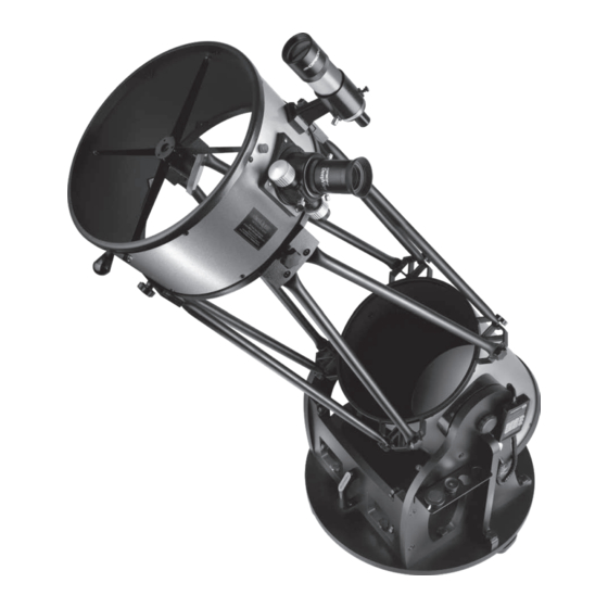
- Page 2 Figure 1. The SkyQuest XX14i IntelliScope Truss Tube Dobsonian...
-
Page 3: Table Of Contents
2. Assembly ......8 event that the telescope needs to be shipped to another loca- tion, or returned to Orion for warranty repair, having the prop- 3. Aligning (Collimating) the Optical System. . . 20 er packaging will help insure that your telescope will survive 4. - Page 4 Battery pack 35mm for cooling fan DeepView IntelliScope eyepiece Object Locator Software Instructions for cooling 10mm Sirius Plössl eyepiece Cooling Washers Cooling fan 9x50 mounting Finder screws Collimation scope Hex keys Finder scope (x3) bracket with O-ring Dust Cover (x2) Upper tube section...
-
Page 5: Parts List
Altitude encoder Manual and board assembly IntelliScope Object Locator Azimuth encoder cable (shorter) Azimuth encoder disk Altitude encoder cable (longer) 9-Volt battery Azimuth encoder board Cable clips (x6) Controller coil cable Encoder connecting Altitude retaining board knob spacer Encoder connect. board Azimuth encoder Hook-and-loop... - Page 6 Large collimation knobs (x3) Washers (x3) Springs (x3) Figure 4. The parts in the box containing the primary mirror and mirror cell. Box #2: Primary Mirror and Cell (refer to Figure 4) Encoder wood screws (1/2" long) Qty. Description Rubber washers Primary mirror Spacers for connecting bolts (10mm long, 15mm dia.)
- Page 7 Left panel Right panel Top baseplate Ground baseplate Metal Front insert Side braces (x2) panel Handle Eyepiece Crescent Hex key rack wrench Altitude tensioning/ Connecting bolts (x12) retaining knobs (x2) Eyepiece rack wood screws Fender washers (x2) Altitude tensioning metal washer Altitude bearing cylinders (x4) Feet (x3) Vertical stop washers...
-
Page 8: Assembly
Dobsonian Base The base of the XX14i was engineered by Orion to allow quick disassembly into several component pieces, to make it more manageable to transport in a standard size vehicle. Assembly is also fast and easy, thanks to a dozen connecting bolts with attached hand knobs. - Page 9 G (x12) S (x12) T (x12) Figure 7. Exploded view of the XX14i base.
- Page 10 Rubber Connecting bolt washer hand knob Insertion tube Washer recessed Spacer Figure 8. (a) Place a rubber washer on the threaded end of the connecting bolt and push it on as far as you can with your fingers. Then use the included insertion tube to push the washer past the Azimuth encoder threads on the bolt and up into the counterbored hole in the wood.
- Page 11 Azimuth encoder board Top baseplate Ground baseplate Brass azimuth bushing Encoder disc Figure 10. Figure 11. Placing a piece of duct, masking, or packing tape Lower the top baseplate onto the ground baseplate. over the hex head of the azimuth axis bolt will keep it from dropping The brass bushing should pass through the center hole in the top downward when you place the top baseplate onto the ground baseplate (and the large hole in the azimuth encoder board).
- Page 12 Right panel Left panel Altitude encoder Encoder wood assembly screws (4x) Encoder Altitude encoder Altitude mounting screw nylon spacer encoder jack washer Azimuth encoder jack Figure 14. Attach the encoder connector board to the left side panel with four of the encoder wood screws and four encoder connector board washers.
- Page 13 Once the primary mirror is installed in the (the end of the handle with the Orion logo should be fac- telescope, there will be no need to remove the mirror, except ing upwards).
- Page 14 Figure 18. Figure 19. To remove the rear end ring, unthread the eight Thread the three counterweight mounting bolts into screws that connect it to the tube. the holes in the rear end ring and tighten them with a wrench. Figure 20.
- Page 15 Truss pole assembly Figure 21. Locate the area of tube that is bulging out and preventing it from seating in the end ring. Press on the bulge to force the tube into the end ring. Clamping knobs Lower Lower tube truss section support...
- Page 16 Figure 24. Rather than assembling the entire optical tube and then hoisting it onto the base, some may find it more convenient to mount the lower tube section on the base first, then install the truss tubes and upper tube section. Note: If desired, you can mount the lower tube section on the base before connecting the truss pole assemblies and upper tube section (Figure 24).
- Page 17 Altitude Truss connector knob Registration side bearing flats Upper truss support ring Altitude tensioning metal washer Altitude tensioning Truss Teflon washer connector Altitude tensioning Figure 27. When the knob in the truss connector is tightened, knob it will clamp the truss connector against the registration flats on the upper truss support ring.
- Page 18 Encoder Tensioner retaining knob Aluminum shaft of altitude encoder assembly Altitude side bearing Black nylon Altitude Right panel thumb screws retaining knob Figure 31. Pull back on the tensioner and slide the finder scope spacer into its bracket until the O-ring is seated in the recess in the front of the bracket.
- Page 19 2" Adapter 1.25" Adapter Thumb screws Coarse focus Coarse focus Thumb screw knob knob Focus lock thumb screw Drawtube tensioning set Fine focus screw knob Figure 33. Figure 34. The 2" DeepView eyepiece installed in the focuser’s The 1.25" Sirius Plössl eyepiece installed in the 2"...
-
Page 20: Aligning (Collimating) The Optical System
Primary mirror center mark drawtube Reflection of primary mirror clip Reflective surface of collimation cap Figure 35. Collimating the optics. When the mirrors are properly aligned, the view down the focuser drawtube should look like this. With the collimation cap in place, if the optics are out of alignment, the view might look something like this. Here, the secondary mirror is centered under the focuser, but it needs to be adjusted (tilted) so that the entire primary mirror is visible. -
Page 21: Aligning The Secondary Mirror
Figure 37. Figure 38. This image shows the XX14i properly set up for To center the secondary mirror axially under the collimation. Note the white paper placed across from the focuser and focuser, hold the mirror holder in place with one hand while adjusting the horizontal orientation of the optical tube. -
Page 22: Aligning The Primary Mirror
completely unthread from the ends of the spider vanes. Also, when making this adjustment, be careful not to stress the spi- der vanes or they could bend. adjusting the Secondary Mirror’s rotational Position The secondary mirror should face the focuser squarely. If the mirror appears to be rotated away from the focuser, the mir- ror’s rotational position will need to be adjusted. -
Page 23: Using Your Telescope
Altitude Out of collimation Collimated Figure 41. A star test will determine if a telescope’s optics are properly collimated. An unfocused view of a bright star through the eyepiece should appear as illustrated on the right if the optics are perfectly collimated. If the circle is unsymmetrical, as in the illustration on the left, the telescope needs collimation. -
Page 24: Focusing The Telescope
Nylon alignment Finder scope bracket thumbscrews (x2) Finder scope Naked-eye view View through finder scope and telescope Focus lock ring Tensioner Figure 44. The view through a straight finder scope (and a reflector telescope) is rotated 180°. Figure 43. The 9x50 finder scope and dovetail bracket. motion;... - Page 25 Magnification Now look through the finder scope. Ideally, the object should be within the field of view. If not, then coarse adjustments to Now that the object you want to view is centered in the 35mm the bracket’s alignment thumb screws will be needed. Once eyepiece, you may want to increase the magnification to get the image is in the finder scope’s field of view, you will now a closer view.
- Page 26 eyepieces. A wider field can be desirable for viewing extended deep-sky objects that are too large to fit within a narrower field of view. Tube Balance With the three counterweights installed on the back of the rear cell, the XX14i optical tube will achieve proper balance with its supplied accessories.
-
Page 27: Astronomical Observing
Figure 46. Figure 47. Loosen the four captive connecting bolts that attach When transporting the disassembled base, lay the the side panels to the front panel. side panels so the encoders face upward and don’t stack anything on top of them, to prevent their getting damaged. 5. - Page 28 (see below). Also, use of a ness of the atmosphere is called the “seeing” condition. light-pollution filter, like the Orion SkyGlow Broadband fil- ter, can mitigate the effects of background sky brightness, In conditions of good seeing, star twinkling is minimal and enhancing the view of faint objects.
-
Page 29: Cooling The Telescope
optics to stabilize. Also, after setting up outdoors, it is a good idea to keep the telescope covered until the Sun sets so the tube does not heat greatly above the temperature of the air. The XX14i comes with a cooling accelerator fan. The fan hastens the equilibration of the primary mirror to the ambi- ent temperature by increasing airflow. - Page 30 objects like planets and double stars. The Moon also takes Jupiter: The largest planet, Jupiter, is a great subject for observation. You can see the disk of the giant planet and higher magnifications well. watch the ever-changing positions of its four largest moons: Deep sky objects, however, typically look better at medium Io, Callisto, Europa, and Ganymede.
-
Page 31: Care And Maintenance
Certain imaging accessories, such You should not have to clean the telescope’s mirrors very as the Orion SteadyPix, can help in obtaining images by the often; normally once every few years or so. Covering the tele- afocal method. - Page 32 washer. It sits directly atop the female threaded post that the hex head bolts screw into. Remove that washer too. Metal washer You may now lift the mirror out of the mirror cell and out of the lower tube section. Do not touch the surface of the mirror with Plastic washer your fingers;...
-
Page 33: Specifications
Accessories Focuser: Dual speed Crayford, 11:1 2" Eyepiece: 35mm Deep View, 2", multi- fine focus knob, accepts 2" coated, threaded for Orion filters and 1.25" eyepieces, all metal 1.25" Eyepiece: 10mm Sirius Plössl, 1.25", construction multi-coated, threaded for Orion Optical tube design:... - Page 34 During this warranty period Orion Telescopes & Binoculars will repair or replace, at Orion’s option, any warranted instrument that proves to be defective, provided it is returned postage paid to: Orion Warranty Repair, 89 Hangar Way, Watsonville, CA 95076. Proof of purchase (such as a copy of the original receipt) is required.