Table of Contents
Advertisement
Quick Links
Copyright
© 1995 by Toshiba Corporation. All rights reserved. Under the copyright laws, this manual
cannot be reproduced in any form without the prior written permission of Toshiba. No patent
liability is assumed, with respect to the use of the information contained herein.
Toshiba T2150CD Series Portable Personal Computer User's Manual
First edition January 1995
Disclaimer
This manual has been validated and reviewed for accuracy. The instructions and descriptions
it contains are accurate for the Toshiba T2150CD Series Portable Personal Computers at the
time of this manual's production. However, succeeding computers and manuals are subject to
change without notice. Toshiba assumes no liability for damages incurred directly or indirectly
from errors, omissions or discrepancies between the computer and the manual.
Trademarks
IBM is a registered trademark and IBM PC, IBM PC XT, IBM PC AT, OS/2, and PS/2 are
trademarks of International Business Machines Corporation.
Intel and DX4 are trademarks of Intel Corporation.
MS-DOS and Microsoft are registered trademarks and Windows is a trademark of
Microsoft Corporation.
Lotus and Lotus 1-2-3 are registered trademarks of Lotus Development Corporation.
QEMM (Quarterdeck Expanded Memory Manager) are trademarks of Quarterdeck Office
Systems.
386MAX is a trademark of Qualitas, Inc.
Sound Blaster and Pro are trademarks of Creative Technology Ltd.
FCC Notice
This equipment has been tested and found to comply with the limits for a Class B digital
device, pursuant to Part 15 of the FCC rules. These limits are designed to provide reasonable
Advertisement
Table of Contents

Related Manuals for Toshiba T2150CD Series


Summary of Contents for Toshiba T2150CD Series
-
Page 1: Fcc Notice
© 1995 by Toshiba Corporation. All rights reserved. Under the copyright laws, this manual cannot be reproduced in any form without the prior written permission of Toshiba. No patent liability is assumed, with respect to the use of the information contained herein. -
Page 2: Industry Canada Requirement
Only peripherals certified to comply with the class B limits may be attached to this computer. Operation with non-certified peripherals or peripherals not operated by Toshiba is likely to result in interference to radio and TV reception. Shielded cables must be used between the external devices and the computer’s or... - Page 3 Toshiba CD-ROM drive XM-1102B** Safety Instruction **means any letters or numbers CAUTION The CD-ROM drive employs a laser system. To ensure proper use of this product, please read this instruction manual carefully and retain for future reference. Should the unit ever require maintenance, contact an authorized service location see Service procedure.
- Page 4 This appliance contains a laser system and is classified as a "CLASS 1 LASER PRODUCT." To use this model properly, read the instruction manual carefully and keep this manual for your future reference. In case of any trouble with this model, please contact your nearest "AUTHORIZED service station."...
- Page 5 ANDEREN VORGÄNGEN ALS IN DER BEDIENUNGSANLEITUNG BESCHRIEBEN KÖNNEN GEFÄHRLICHE STRAHLENEXPOSITIONEN ZUR FOLGE HABEN. Toshiba service procedure Should this product require maintenance, contact the following Toshiba service station. TOSHIBA AMERICA INFORMATION SYSTEMS, INC. DISK PRODUCTS DIVISION 9740 IRVINE BOULEVARD IRVINE, CA. 92718 TEL: 714-583-3000 TOSHIBA EUROPA (I.E.) G.m.b.H.
- Page 6 This manual tells how to set up and begin using your T2150CD series computer. It also provides detailed information on configuring your computer, basic operations and care, using optional devices and troubleshooting.
-
Page 7: Key Operation
Keys The keyboard keys are used in the text to describe many T2150CD series computer operations. A distinctive typeface identifies the key top symbols as they appear on the keyboard. For example, Enter identifies the Enter key. - Page 8 Some operations require you to simultaneously use two or more keys. We identify such operations by the key top symbols separated by a plus sign (+). For example, Ctrl + C means you must hold down Ctrl and at the same time press C. If three keys are used, hold down the first two and at the same time press the third.
-
Page 9: Equipment Checklist
Chapter 1 Introduction This chapter provides an equipment checklist and it identifies the T2150CD series computer’s features, options and accessories. CAUTION Some of the features described in this manual may not function properly if an operating system other than preinstalled Toshiba MS-DOS is used on the computer. - Page 10 The T2150CD series computer uses Toshiba’s advanced Large Scale Integration (LSI), Complementary Metal-Oxide Semiconductor (CMOS) technology extensively to provide compact size, minimum weight, low power usage, and high reliability. This computer...
- Page 11 115 and 240 volts. Hard disk drive The T2150CD series computer has a 520 million byte (500MB), integrated, 2 1/2” hard disk drive for nonvolatile storage of data and software. CD ROM Drive A full-size, double-speed internal CD ROM drive lets you run 12 cm (4.72”) or 8 cm (3.15”)
- Page 12 Port replicator port This port enables connection of an optional port replicator, which provides the ports available on the T2150CD series computer, in addition to a PS/2 mouse, a MIDI/Joystick and audio line-out ports. PCMCIA card slot A Personal Computer Memory Card International Association (PCMCIA) slot can accommodate two 5 mm cards (Type II) or one 10.5 mm (Type...
-
Page 13: Special Features
Special Features The following features are either unique to Toshiba computers or are advanced features, which make the T2150CD series computer more convenient to use. RAMDRIVE You can use the MS-DOS RAMDRIVE.SYS driver to allocate part of the computer’s memory to a virtual disk called a RAMDRIVE. - Page 14 TSETUP program has elapsed. The feature works only in Resume mode. Advanced power manager The T2150CD series computer’s CPU automatically goes into a halt state when it is not used for a specific time period. This function saves battery power.
- Page 15 Options You can add a number of options to make your T2150CD series computer even more powerful and convenient to use. The following options are available: Memory expansion A 4, 8, 16, 24 MB small outline SIMM can be easily inserted into the computer’s memory slot...
-
Page 16: The Grand Tour
Chapter 2 The Grand Tour This chapter identifies the various components of your T2150CD series computer. Become familiar with each component before you operate the computer. Front With Display Closed Figure 2-1 shows the computer’s front with its display panel in the closed position. -
Page 17: Left Side
Left Side Figure 2-2 shows the computer’s left side. Figure 2-2 The left side of the T2150CD series computer External 3 1/2" diskette drive port This port lets you connect a 3 1/2” diskette drive for transferring data to or from removable diskettes. -
Page 18: Right Side
PCMCIA cards (Type II) or one 10.5 mm PCMCIA card (Type III). You can install any industry standard PCMCIA card such as a SCSI adapter, Ethernet adapter or flash memory card. Microphone jack A standard 3.5 mm mini line-in jack enables connection of a monaural microphone or other device for audio input. -
Page 19: Back Side
Figure 2-3 The right side of the T2150CD series computer CD ROM drive A full-size, double-speed CD ROM drive lets you run 540MB CD ROMs. To open the CD ROM drawer, push the button on the drawer’s door. Refer to Chapter 4, Operating Basics Contrast control Use this dial to adjust the screen’s readability. - Page 20 Figure 2-5 shows the underside of the computer. Make sure the display is closed before turning over your computer. Figure 2-5 The underside of the T2150CD series computer Port replicator notches Notches are available to secure the port replicator in place.
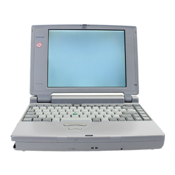
- Page 21 expansion section in Chapter 12, Optional Devices. Front With Display Open Figure 2-6 shows the front of the computer with the display open. To open the display, press the display latch and lift the display up. Position the display at a comfortable viewing angle. Figure 2-6 The front with the display open Display screen The LCD displays high-contrast text and graphics and...
-
Page 22: Indicator Panel
Operating Basics AccuPoint control buttons Control buttons below the keyboard let you select menu items or manipulate text and graphics designated by the on-screen pointer. Indicator panel The indicator panel provides icons for monitoring the status of various computer functions. Details are given in the next section. - Page 23 Arrow mode When the Arrow mode icon lights green, you can use the keypad overlay (white labeled keys) as cursor keys. Refer to the Keypad overlaysection in Chapter 6, The Keyboard. Numeric mode You can use the keypad overlay (white labeled keys) for numeric input when the Numeric mode icon lights green.
-
Page 24: Getting Started
If you are an experienced user, read the section on backing up your preinstalled software. Use the backup feature of the Toshiba Companion Utility, not MS-DOS, to make the backup diskettes. Also, glance over the rest of the chapter for any material that might be new to you. -
Page 25: General Conditions
strain to your hands, wrists or other joints. Proper ambient conditions should also be maintained for the computer’s operation. This section discusses the following topics: General conditions Placement of the computer and peripheral devices Seating and posture Lighting Work habits General Conditions In general, if you are comfortable, so is your computer, but read the following to make sure your work site provides a proper environment. -
Page 26: Seating And Posture
display should be angled to reduce glare and maximize visibility. If you use a paper holder, set it at about the same height and distance as the computer. Seating and Posture The height of your chair in relation to the computer and keyboard as well as the support it gives your body are primary factors in reducing work strain. -
Page 27: Connecting Power Cord
Connecting Power Cord T2150CD series computers are equipped with build-in converter circuits that eliminate the need for an external AC adapter. Simply connect the supplied power cord to the computer and a power source supplying 115 to 240 volts, when you need to charge the battery or want to operate from AC power. -
Page 28: Chapter 4, Operating
2. Even when you’re using the power cord, you should have a battery pack installed to protect the battery contacts. When you purchase your T2150CD series computer, the battery is completely discharged. To charge the battery pack so you can operate the computer on battery power, simply leave the AC power cord connected with the computer’s power turned off. - Page 29 Connecting 3 1/2" External Diskette Drive To connect the drive, follow the steps below and refer to Figures 3-3 and 3-4. Plug the connecting cable’s larger connector into the 3 1/2” external diskette drive’s socket. Press the latches on either side of the connector when you plug in the connector. NOTE The connectors are designed so they cannot be misconnected.
-
Page 30: Opening The Display
When you use the diskette drive, connect the drive before you turn on the computer. If the drive is connected after the computer is turned on, the computer may not recognize the connection. In this case you must restart the computer after the drive is connected. Disconnecting 3 1/2"... -
Page 31: Turning On The Power
Should any MS-DOS or Microsoft Windows for Workgroups files be damaged, you will need to restore them from backup diskettes. For making backup diskettes, you must make Toshiba Companion Utility diskette. Refer to your documentation for procedures on making Toshiba Companion Utility diskette and backup diskettes of files installed on your hard disk. -
Page 32: Inserting And Removing Diskettes
The external 3 1/2” diskette drive provides a convenient means of transferring and storing data. To insert a 3 1/2” diskette into the T2150CD series computer: Hold a diskette with the insertion-arrow side up (hub side down). The metal protective cover should point toward the diskette drive. - Page 33 One set of utilities, which includes BACKUP.EXE, RESTORE.EXE, TSETUP.EXE, TDIAGS.EXE and others, has been set up for installation on a separate diskette. Before backing up the files on your hard disk, follow the steps below to make a Toshiba Companion Utilities diskette.
-
Page 34: Using The Backup Command
To use the BACKUP command, connect the external diskette drive if it is not already connected and follow the steps below. Insert the Toshiba Companion Utility diskette into the diskette drive and press Ctrl + Alt + Del. The Toshiba ACCESS Utility appears. Press Enter. -
Page 35: Installing Application Software
To use the RESTORE command, connect the external diskette drive if it is not already connected and follow the steps below. Insert the Toshiba Companion Utility diskette into the diskette drive. At the C:\> prompt type: A:RESTORE A: C: /S... -
Page 36: Restarting The Computer
Make sure all disk activity has stopped, then remove any CD-ROM from the internal drive and any diskette from the external 3 1/2” diskette drive. CAUTION Make sure the Disk icons are off. If you turn off the power while a disk is being accessed, you can lose data or damage the disk. -
Page 37: Operating Basics
This chapter gives details on basic operations including accessing disk drives, charging the batteries, using the keyboard’s ten-key pad overlay, adjusting the display, using AccuPoint and tips on caring for your T2150CD series computer. Identifying Drives MS-DOS and software programs identify disk drives by the letters A, B, C, D, E and so forth. -
Page 38: Main Battery
Include the file’s path name in the PATH command you are currently using. Refer to your MS-DOS documentation for information on the PATH command. Main Battery The T2150CD series computer provides easy procedures for charging the main battery and monitoring its status. Charging the Battery... -
Page 39: Battery Led
connected to the computer and a power outlet. With the AC power cord connected as described in Chapter 3, Getting Started, and the computer turned off, it takes about 2.5 hours to bring a discharged battery up to full charge. For details on charging and replacing the main battery, see Chapter 7, Power and Power-Up Modes. -
Page 40: Using Accupoint
Chapter 6, The Keyboard. MaxTime Double click the Toshiba Utilities icon in the Windows Program Manager, then double click the MaxTime icon to display a MaxTime window showing the current battery status. You can also use this window to set battery save options, sound system controls and other system configurations. - Page 41 Figure 4-2 Example of hand position for using the AccuPoint Replacing AccuPoint Cap Five spare AccuPoint caps are supplied with the T2150CD series computer. These caps are expendable items that should be changed after prolonged use. To remove the AccuPoint cap, firmly grasp the cap and pull it straight up.
- Page 42 Figure 4-4 Pressing the CD ROM drawer button Grasp the drawer gently and pull until it is fully opened. Figure 4-5 Pulling the drawer open Lay the CD, lable side up, in the drawer. Press gently at the center to make sure it is seated securely on the spindle.
-
Page 43: Using Microphone
Figure 4-7 Closing the CD ROM drawer To remove the CD, follow the steps below and refer to figure 4-8. Press the eject button and gently pull the drawer out until it is fully opened. There are indentations on the sides of the drawer to let you grasp the CD. Hold it gently and lift it out. -
Page 44: Record Monitor
This feedback occurs repeatedly and causes a very loud, high-pitched noise. It is a common phenomenon that occurs in any sound system when the microphone input is output to the speaker (throughput) and the speaker volume is too loud or too close to the microphone. You can control throughput by adjusting the volume of your speaker or through the Record Monitor or Mute functions. -
Page 45: Arrow Mode
Figure 4-9 Numeric and arrow overlay To turn on the numeric mode and press Fn + F11, the Numeric mode icon lights. Now try numeric data entry. Arithmetic functions are also available for calculations as indicated by the white marking on the keys. -
Page 46: Cleaning The Computer
Moving the Computer The T2150CD series computer is designed for rugged durability. However, a few simple precautions taken when moving the computer will help assure trouble-free operation. Make sure all disk activity has ended before moving the computer. Check the Disk icon on the computer and the indicators on any external disk drives. -
Page 47: Hard Disk Drive
Chapter 5 Disks and Disk Drives Your T2150CD series computer has a number of data storage features. This chapter introduces the computer’s data storage devices and describes how to use them. Types of Disk Drives The following data storage devices are available: Hard disk drive An internal 2 1/2”, 520 million byte (500MB) hard... -
Page 48: Cd-Rom Drive
The area allocated to an operating system is called a partition. Each partition must be set up by the corresponding operating system. MS-DOS uses the FDISK command to create its partition. The MS-DOS documentation explains how to create directories and subdirectories within the partition. - Page 49 When inserted in a drive, a diskette spins in its jacket and its metal protective covering slides back exposing the diskette’s magnetic surface. The diskette drive reads from and writes to a diskette by contacting the diskette’s magnetic surface. A write-protect tab is located at the corner. The section below tells how to write-protect a 3 1/2”...
-
Page 50: Diskette Care
Figure 5-2 The write-protect tab To write-protect a 3 1/2” diskette, slide the write-protect tab to the outermost position. You should be able to see through the write-protect opening. To write-enable a diskette, slide the tab toward the innermost position. The write-protect opening should be covered. -
Page 51: Formatting Disks
RAMDRIVE Since a RAMDRIVE, is created in the computer’s memory it provides almost instantaneous access to your data. Unlike physical disks, which must be spun like a phonograph record and searched for data, no mechanical process is involved in retrieving data from a RAMDRIVE. RAMDRIVEs are formatted and used similarly to physical disks. - Page 52 Depending on the type of diskette you are formatting, type one of the following commands at the system prompt: format a: formats a 2HD diskette to hold 1.44MB. format a:/s formats a 2HD diskette to hold 1.44MB and copies the MS-DOS system files on it. format a:/f:720 formats a 2DD diskette to hold 720KB.
- Page 53 Insert a blank, formatted disk into drive A: Type sys a: and press Enter. MS-DOS copies the system files to the disk. You can also create a system disk by adding /S to the MS-DOS FORMAT command when you format a disk. To use a system disk, insert it in drive A: and turn on the computer. You must format a hard disk or a diskette as a system disk in order to automatically start or restart the system from that disk.
- Page 54 Use non-system diskettes to back up important personal files and software such as MS-DOS and Windows for Workgroups from your hard disk or diskettes. It’s a good idea to write protect backup diskettes and store them in a safe place.
-
Page 55: F1 ... F12 Function Keys
Chapter 6 The Keyboard All T2150CD series computers’ keyboard layouts are compatible with a 101/102-key enhanced keyboard. By pressing some keys in combination, all the 101/102-key keyboard functions can be executed on the computer. The number of keys on your keyboard depends on which country’s keyboard layout your computer is configured with. - Page 56 Used in combination with the Fn key, keys marked with icons execute specific functions on the T2150CD series computer. See the section, Soft keys: Fn key combinations, in this chapter. The function executed by individual keys depends on the software you are using.
- Page 57 Pressing Shift on either the left or right side of the keyboard changes the keyboard mode, providing access to upper-case characters, and the symbols above the number keys. Shift functions only as long as you continue to hold it down. If the Caps Lock key is on, Shift produces lower-case characters.
- Page 58 Ctrl + Pause (Break) or Ctrl + C halts program execution. NOTE Some application programs use Ctrl + S or Ctrl + C to execute other functions. Such applications may use other key combinations to suspend or halt program execution. Pressing PrtSc in MS-DOS and some applications sends the current contents of the display to the printer.
-
Page 59: Soft Keys: Fn Key Combinations
Soft Keys: Fn Key Combinations The Fn (function) is unique to Toshiba computers and is used in combination with other keys to form soft keys. Soft keys are key combinations that enable, disable or configure specific features. - Page 60 Press Fn + F10 (arrow mode) or Fn + F11 (NumLock) to access the integrated keypad. When activated, the light gray keys with white numbers can be used for cursor control or numeric data entry. Refer to the Keypad overlay section in this chapter for more information on how to operate these keys.
-
Page 61: Battery Save Mode
Hotkeys (Fn + a function or cursor key) let you enable or disable certain features of the T2150CD series computers. Instant Security Press Fn + F1 to lock the keyboard and blank the screen to prevent others from accessing your data. To restore the computer operation, enter the password. See... - Page 62 Pressing Fn + F3 toggles between Resume mode and boot mode. When you press Fn + F3 in a DOS environment, the Pop-up window below appears at the top left of the display, showing the current power up mode. Continue holding down Fn and press F3 again to change the setting.
-
Page 63: Keyboard Layout
Emulating Fn Key on External Keyboard The Fn key is only on Toshiba keyboards. If you use an external keyboard attached to the computer or to an optional port replicator, you can execute Fn key combinations by emulating the Fn key. -
Page 64: Keypad Overlay
Keypad Overlay Your computer’s keyboard does not have an independent numeric keypad, but its numeric keypad overlay functions like one. The keys in the center of the keyboard with white letters make up the numeric keypad overlay. The overlay provides the same functions as the numeric keypad on the 101/102-key enhanced keyboard in Figure 6-2. -
Page 65: Generating Ascii Characters
Figure 6-2 The numeric keypad overlay Temporarily Using the Normal Keyboard (overlay on) While using the overlay, you can temporarily access the normal keyboard without turning off the overlay: Hold Fn and press any other key. All keys will operate as if the overlay were off. Type upper-case characters by holding Fn + Shift and pressing a character key. - Page 66 Hold Fn + Alt. Using the overlay keys, type the ASCII code. Release Fn + Alt, and the ASCII character appears on the display screen. A list of ASCII characters with their codes is in Appendix...
-
Page 67: Power Conditions
Chapter 7 Power The computer’s power resources include the AC power cord and internal batteries. This chapter gives details on making the most effective use of these resources including charging and changing batteries, tips for saving battery power, and power up modes in DOS and Windows. - Page 68 No battery installed {bmcrnbullet.bmp} • No charge Operates • LED: {bmcrnbullet.bmp} Battery off No charge AC IN green {bmcrnbullet.bmp} LED: Battery off AC IN green AC cord not Battery charge is {bmcrnbullet.bmp} connected above low battery Operates trigger point {bmcrnbullet.bmp} LED: Battery off AC IN off...
-
Page 69: Power Leds
LED: Battery off AC IN off Power LEDs As shown in the above table, LED indicators on the front of the computer alert you to the computer’s operating capability and battery charge status. Battery LED Check the Battery LED to determine the status of the main battery. The following LED lights indicate the battery status: Flashing orange The battery charge is low. -
Page 70: Backup Battery
AC power cord is not attached. You can purchase additional battery packs for extended use of the computer away from an AC power source. One battery pack model is interchangeable among T2150CD series computers. -
Page 71: Care And Use Of The Battery Pack
Only one battery can be installed in the T2150CD series at a time; however, if batteries for the computer are connected in series for other use, it is recommended that all batteries be replaced at the same time. - Page 72 The Battery LED glows orange when the battery is being charged. CAUTION Use only the T2150CD series computer connected to an AC power source or the optional Toshiba Battery charger to charge the battery pack. Do not attempt to charge the battery pack with any other charger.
- Page 73 The battery completely discharged and left in the computer for a long time. A cool battery is installed in a warm computer. In such case, follow the steps below. Fully discharge the battery by leaving it in the computer with the power on until the power automatically shuts off.
-
Page 74: Maximizing Battery Operating Time
How long the charge lasts in a battery depends on: How you configure the computer (for example, whether you enable battery-power saving options) The T2150CD series computers provide a battery save mode to conserve battery power. This mode has the following four options:... -
Page 75: Extending Battery Life
Closing the display when you are not using the keyboard saves power. Operating time decreases at low temperatures. The condition of the battery terminals. Make sure the battery terminals stay clean by wiping them with a clean dry cloth before installing the battery pack. Retaining Data With Power Off When you turn off your computer with fully charged batteries, the batteries retain data for the following approximate time periods:... -
Page 76: Removing A Battery Pack
Be careful not to pull too hard or try to lift the battery pack more than about a finger’s width. Grasp the battery pack and lift it out. CAUTION For environmental reasons, do not throw away a spent battery pack. Please return spent battery packs to your Toshiba dealer. -
Page 77: Installing The Battery Pack
To install a battery pack, follow the steps below. CAUTION There is danger of explosion if the battery is incorrectly replaced. Use only the same or equivalent battery recommended by Toshiba. Return spent batteries to your dealer for environmentally safe disposal. - Page 78 tightly or to pinch it by the carrying case or other object. Starting the Computer With the Password If you registered the password, you must enter the password to start up the computer. If you forget the password, use the password service diskette For more information about how to set a password and make the password service diskette, refer to the Password security section in Chapter 11, Setup and Password...
-
Page 79: Power-Up Modes
Set Password Again? (Y/N) Press Y to run the TSETUP program and set a new password. Press N to restart the computer. NOTES 1. The password service diskette must be inserted in drive A, otherwise the display will return to . - Page 80 Do not turn the computer back on right away. Wait a few seconds. AutoResume Mode One of the T2150CD series computers’ most useful features is AutoResume. This feature lets you turn the computer’s power off without exiting your software application. When you turn the power on again, you can resume work where you left off, because the screen display is restored as you left it.
- Page 81 power on: Confirms that resume mode is enabled. Restarts the hard disk. Restores the system, including data in memory, to its state immediately prior to shutdown. Restores the screen display as you left it. AutoResume does not save your files to a physical disk. It maintains the information in memory so you can start your application without reloading it when you turn the computer on again.
- Page 82 The display will show the same screen that appeared when you turned off the power. If you experience any difficulties with AutoResume, refer to the sections AutoResume precautions and AutoResume error conditions, which follow in this chapter. Automatic Enabling of AutoResume The system automatically shuts down if the battery pack becomes completely discharged and the AC power cord is not supplying power.
-
Page 83: Panel Power On/Off
You’re running a program that does not use the T2150CD series computer’s BIOS. Panel Power On/Off You can set up your T2150CD series computer so that power turns on automatically when you open the display panel and turns off when you close it. -
Page 84: Display Panel
Chapter 8 Display Panel The T2150CD series computers are equipped with either a color advanced STN Liquid Crystal Display (LCD) or a color TFT LCD display. This chapter explains functions of color displays, external monitors and the display controller. Displaying Images Images are formed on the display by dots called pixels. -
Page 85: Video Ram
25 lines of standard text 80 characters wide. The T2150CDT displays up to 64K colors and the T2150CDS displays up to 256 colors. A high-resolution external monitor connected to a T2150CD series computer can display up to 1024 horizontal and 768 vertical pixels and up to 64K colors. -
Page 86: Text Mode
Selecting video mode section later in this chapter. Text Mode In text mode, each pel is called a character cell, as illustrated below. The display for each cell is limited to a predefined character. Appendix B, ASCII Character codes shows the available character set. -
Page 87: Selecting Video Mode
Selecting Video Mode How your software displays information on the LCD depends on the mode it uses. The T2150CD series computer supports a number of video modes, which determine the screen mode (text or graphics), resolution and the number of colors available. - Page 88 Pels VGA Grph 640 x 200 8 x 8 2 of 256K 2 of 256K 70Hz 31.5KHz Pels VGA Text 80 x 25 8(9) x 14 Mono Mono 70Hz 31.5KHz Characters VGA Text 80 x 25 8(9) x 16 Mono Mono 70Hz 31.5KHz...
- Page 89 Grph Pels SVGA 640 x 400 8 x 16 256 of 256 of 60 Hz 31.5 KHz Grph Pels 256K 256K Table 8-2 T2150CDS Video modes Video Type Resolution Character T2150CDT mode matrix colors vertical horizontal (pels) colors refresh refresh rate rate 0, 1...
- Page 90 VGA Grph 640 x 350 8 x 14 16 of 16 of 256K 70 Hz 31.5KHz Pels 222K† VGA Grph 640 x 480 8 x 16 2 of 222K† 2 of 256K 60 Hz 31.5KHz Pels VGA Grph 640 x 480 8 x 16 16 of 16 of 256K...
- Page 91 32K out of 32K colors and 64K out of 64K colors. Using an External Color Monitor The T2150CD series computers support VGA and Super VGA video modes. You can use a high-resolution monitor connected to the external monitor port on the computer or to the external monitor port on an optional port replicator.
- Page 92 When you connect an external monitor and turn on the computer’s power the computer automatically recognizes the monitor and determines whether it is color or monochrome. You do not have to make any settings to use an external monitor. However, you can select from the following options: External monitor only Internal LCD only...
-
Page 93: Types Of Memory
Memory Optimal memory configuration can greatly enhance the performance of your computer. The T2150CD series computers provide several tools for customizing memory configuration to best suit your software and system. This chapter introduces memory concepts and explains how to configure memory, and how to create and use various memory devices such as RAMDRIVEs. -
Page 94: Memory Map
Using RAM Manufacturers of personal computers have adopted the following names to describe the functions of various parts of RAM: Conventional memory Upper memory High memory Extended memory Expanded memory The following memory map shows how RAM is allocated. Memory Map This diagram illustrates how your computer allocates memory. -
Page 95: Extended Memory
Shadow BIOS ROM. Expanded Memory Some software packages that run under Toshiba MS-DOS can use memory beyond 640KB as a work area. These applications were designed according to a standard known as Expanded Memory Specification (EMS) which was jointly developed by Lotus, Intel, and Microsoft Corporations. - Page 96 LIM-EMS and Optional Additional Memory T2150CD series computers come with 4096KB or 8192KB of RAM memory. If you plan to use large spreadsheets or process complicated graphics, you may want to expand the computer’s memory capacity by installing optional memory cards. Refer to...
-
Page 97: Real Mode
A RAMDRIVE is volatile. So you must save data in it to a diskette or hard disk before you turn off or reset your computer. Enabling the AutoResume feature will save data in a RAMDRIVE when the power is turned off. However, even with AutoResume, if you reset your computer with the reset button or with Ctrl + Alt + Del, your data will be lost. -
Page 98: Protected Mode
Protected Mode Protected Mode was introduced with the 80286 microprocessor. The primary advantage of protected mode is its ability to let the processor directly access all available memory. In protected mode, all the instructions and architectural features are available to the microprocessor, so all applications have access to the full range of extended memory. -
Page 99: List Of Utilities And Drivers
Chapter 10 Toshiba Utilities and Drivers Toshiba utilities and drivers are preinstalled on your hard disk. This chapter describes the utilities and drivers and provides references to the relevant chapter describing each one. Be sure you have backed up the utilities and drivers, along with other preinstalled software, onto diskettes. -
Page 100: Accessing System Setup
Chapter 11 Setup and Password Security This chapter explains how to use TSETUP and MaxTime options to configure the T2150CD series computer. It also describes how to set the power on and instant security password to prevent others from accessing your data. When you configure the computer with TSETUP, the computer stores your selected values in memory that is backed up by the internal battery powered Real Time Clock (RTC). -
Page 101: Factory Preset Configuration
T2150CD series computer is in Resume mode. 3. The option appears only when the system Battery Level cannot detect the battery charge. For example, when the battery is replaced. 4. The T2150CDS options are 222k and LDC Display Colors 4096 colors. -
Page 102: Setup Options
NOTE The functions described in this section can also be changed using Toshiba's Hardware Setup program in Windows. You can access this program in the Toshiba Utilities group in Windows Program Manager. Memory This group provides information on the computer’s memory. -
Page 103: Power On Display
LCD Display Mode The computer’s LCD displays text in 80 characters by 25 lines and graphics in 640 by 480 pixels for either mode. Use this option to set the computer’s display Color Monochrome mode to Color Monochrome selects color mode. (This is the default.) Color selects monochrome mode. - Page 104 Simultaneous Selects both the internal LCD and the external CRT for simultaneous display. NOTE When starting the computer in Resume mode, the last configuration is remembered. If data does not appear on the display you are using after starting in Resume mode, press Fn + Text Mode Stretch Text mode stretch enables a larger display area of 680 x 480 pixels in text mode.
- Page 105 BATTERY SAVE OPTIONS CPU Sleep Mode Enabled Display Auto Off 03 Min. HDD Auto Off 03 Min System Auto Off 30 Min. LCD Brightness Semi-Bright NOTE In boot mode, is not displayed. System Auto Off User Setting This option, allows you to set the battery save parameters on the sub-window, BATTERY SAVE OPTIONS When you select this option, the automatic setting...
-
Page 106: Battery Level
30 minutes. HDD Auto Off Use this option to disable or set the duration of the HDD automatic power off function. Disabled disables HDD automatic power off. xx Min. automatically turns off power to the hard disk drive if it is not used for the duration set. The duration be set to 1, 3, 5, 10, 15, 20 or 30 minutes. -
Page 107: Optional Devices
Chapter 12 Optional Devices Optional devices can expand the T2150CD series computer’s capabilities and its versatility. This chapter describes connection or installation of the following types of devices: Cards/Memory PCMCIA cards Memory modules Power Devices Additional battery pack Battery charger... -
Page 108: Installing The Pcmcia Card
SCSI adapter Flash memory Network adapter Installing the PCMCIA Card Two PCMCIA connectors are located one above the other on the left side of the computer. Both connectors are accessed from the same slot. You can install two Type II cards, one in each connector, or one Type III card in the bottom connector. - Page 109 If you need to access the card, simply open the corresponding flap. Figure 12-3 The card's slot cover After installing the card, check the configuration in the T2150CD series computer’s TSETUP program to make sure it is appropriate for your card. Refer to the Card Manager User's Guide and to your card’s documentation for setup information.
-
Page 110: Memory Expansion
Close the cover. Memory Expansion You can install a memory module in the computer’s Small Outline SIMM socket to increase the amount of RAM to a maximum of 28MB in the T2150CDS or 32MB in the T2150CDT. Refer to Chapter 8, Memory, for details on configuring your expansion memory. -
Page 111: Removing Memory Module
CAUTION Do not touch the connectors on the memory module or on the computer. Debris on the connectors may cause memory access problems. Figure 12-6 Inserting the memory module The module is held up by springs in the computer’s socket. Gently push the module into place until two latches close over each side. -
Page 112: Additional Battery Pack
AC power cord connected to the computer. Port Replicator In addition to the ports available on the T2150CD series computer, a port replicator provides an audio line-out jack and PS/2 mouse and joystick ports. The port replicator connects directly to the port replicator port on the back of the computer so no cabling is necessary. An AC adapter, included with your port replicator, connects to the port replicator to a power source. - Page 113 Figure 12-8 The front Computer connector This is the computer interface. It connects directly to the T2150CD series computer’s port replicator port. Connecting lever This lever assures proper connection between the port replicator and computer when the computer is aligned on the port replicator’s plastic guide pins.
- Page 114 computer to hold it securely to the port replicator. Back Figure 12-9 shows the port replicator’s back. Figure 12-9 The back DC IN The AC adapter’s DC outlet plug connects to this socket. Use only the AC adapter that came with your port replicator.
-
Page 115: Connecting The Port Replicator
PS/2 keyboard Use this port to connect a PS/2 keyboard. PS/2 mouse Use this port to connect a PS/2 compatible pointing device. Ground The ground screw is used to attach a grounding cable to protect the computer against a telephone line power surge when a card modem is installed. - Page 116 Turn off the computer. Disconnect any peripheral devices connected to the computer. Lift up the connecting lever on top of the port replicator. Figure 12-10 Lifting up the connecting lever Seat the computer onto the port replicator’s guide pins. Be sure holes on each back corner of the computer’s underside fit onto the pins.
-
Page 117: Connecting The Ac Adapter
Figure 12-12 Completing the connection Connecting the AC Adapter To supply power to the computer, connect the AC adapter as described below. Attach the power cord to the AC adapter. Plug in the AC adapter cable. Figure 12-13 Connecting the AC adapter Disconnecting the Port Replicator To disconnect the port replicator, follow the steps below. -
Page 118: External Monitor
The cable’s connectors are designed so that it is impossible for you to connect them incorrectly. You can also connect a parallel printer to an optional port replicator. See the Port replicator section in this chapter. To connect a printer, follow these steps: Turn off the computer. - Page 119 Turn the computer on. The computer automatically recognizes the external monitor and sends output to it. If you have selected under the options of the TSETUP program, both the Simultaneous Display external monitor and the internal LCD will be active when you turn on the computer. If is selected, only the external monitor will be active.
-
Page 120: International Keyboards
To disconnect the keyboard, turn off the computer and pull out the keyboard connector. International Keyboards Eight international keyboards are available for the T2150CD series computers. The 82-key U.S. English keyboard must be replaced with an 84-key keyboard in order to fit the international key cap sets. - Page 121 A security lock enables you to anchor your computer and an optional port replicator to a desk or other heavy object to help prevent unauthorized removal of the computer or port replicator. Attach one end of a cable to the desk and the other end to the security lock slot on the left side of the computer and to the optional port replicator as shown below.
-
Page 122: Communication Settings
Cabling The computer’s RS-232-C serial port is an IBM PC style serial interface. It has an IBM PC AT, D-shell, male connector. This connector has 9 pins instead of the conventional 25 pins. To connect any serial device to the computer, you need the same cable that you would use to connect that device to an IBM PC XT. -
Page 123: Connecting A Serial Printer
The configuration of the communications parameters. (The parameters of both devices must match.) Use the MODE command to set these parameters on the computer as described in the MS-DOS documentation. Many communications software packages also provide ways to set communications parameters. -
Page 124: Connecting A Serial Mouse
connect other serial devices you may want to compare their requirements as well. You can usually configure your computer to be compatible with your printer by using the printer’s documentation. Also, the MODE command lets you set up the computer’s parameters. -
Page 125: Troubleshooting
Chapter 13 Troubleshooting Toshiba designed the T2150CD series computers for durability. However, should problems occur, following the procedures in this chapter can help to determine the cause. All readers should become familiar with this chapter. Knowing what might go wrong can help prevent problems from occurring. -
Page 126: Analyzing The Problem
Inspect all connecting cables for loose wires and all connectors for loose pins. Check that your diskette is correctly inserted and that the write protect tab is correctly set. Make notes of your observations and keep them in a permanent error log. This will help you describe your problems to your dealer. -
Page 127: Hardware And System Checklist
Self Test Power Sources Power-on Password Self Test To run the computer’s self-test, hold down the space bar and turn on the computer. The following will be displayed: (c) Copyright xxxx Toshiba Corp. All rights reserved. Self Test . . . -
Page 128: Power Sources
Memory Test xxxxKB Test Complete This message remains on the screen for a few seconds while the computer tests its memory. If the self test is successful, a short beep sounds and the computer tries to load MS-DOS. Depending on how the Boot Priority is set in the TSETUP program, the computer tries to load first from drive A then from drive C, or first from drive C then from drive A. -
Page 129: Chapter 7, Power And Power-Up Modes
Battery doesn’t charge when the AC If the battery is completely discharged, it will not begin power cord is attached (AC IN indicator charging immediately. Wait a few minutes. should glow green) If the battery still does not charge, make sure the outlet is supplying power. - Page 130 the cord is frayed or damaged, replace it. If the terminals are soiled, wipe them with cotton or a clean cloth. If the AC power cord still does not power the computer, contact your dealer. Password If you forgot your password, you can use your password service diskette to start the computer.
-
Page 131: Lcd Panel
reassigning the meaning of each key. See your software’s documentation. No output from keyboard Is an external keyboard connected? If one is connected, the internal keyboard is disabled. If you are still unable to use the keyboard, consult your dealer. LCD Panel Apparent LCD problems may be related to the computer's setup. -
Page 132: Chapter 5, Disks
See the CD care section in Chapter 5, for details on cleaning. Check your config.sys and autoexec.bat files to make sure they have the necessary drivers and execution lines. Refer to the CD-ROM driver section in Chapter 10, Toshiba Utilities and Drivers. -
Page 133: Diskette Drive
Some CDs run correctly, but others do The software or hardware configuration may be causing a problem. Make sure the hardware configuration matches your software’s needs. Check the CD's documentation. Check the type of CD you are using. The drive supports audio CDs, photo CDs and ISO 9660. - Page 134 documentation for file recovery procedures. It is common for software to automatically create backup files. If your main file is damaged, you can often rename and use the backup file. You may be able to recover lost data by using The Undelete uitlity in Windows of by using another utility software.
-
Page 135: Pointing Device
If the pointer on screen does not respond as you expect or if it is hard to see, check the settings in the AccuPoint setup program described in Chapter 10, Toshiba Utilities and Drivers. If you are using a PS/2 or serial mouse, also refer to... - Page 136 Problem Procedure On-screen pointer does not respond to If a PS/2 or serial mouse is connected, check the AccuPoint operation Setup program. The option in the Pointing Device option box should be set to Others Simultaneous to use both the AccuPoint and an external mouse. Make sure the following lines are contained in your AUTOEXEC.BAT file: PATH %PATH%;C;\MOUSE...
-
Page 137: Pcmcia Card
On-screen pointer does not respond to Check for a firm connection between the computer’s serial mouse operation (or port replicator’s) serial port and the cable’s 9-pin connector. Did you connect the mouse before turning on the computer? Is the option in the TSETUP program Serial port set properly? Confirm that your CONFIG.SYS or... -
Page 138: Diagnostic Test
Display error occurs Check that the cable connecting the external monitor to the computer or port replicator is attached firmly and that the port replicator is securely connected to the computer. Run the diagnostic test program. If problems persist, contact your dealer. Expanded Memory Refer also to Chapter 9,... -
Page 139: Test Sequence
Go to drive C and at the DOS prompt C:\>, type TDIAGS. MS-DOS loads the diagnostic test and displays the following screen: TOSHIBA personal computer xxxx DIAGNOSTICS version x.xx (c) copyright TOSHIBA Corp. 19xx Test the DIAGNOSTICS (Y/N) To execute the program type Y; to exit, type N. - Page 140 System test Memory test Display test Floppy Disk (Diskette) test Hard disk test Printer test When a test is in progress, the program displays: IN PROGRESS TTSSDSS where TT indicates the test number, the first SS indicates the subtest number, D indicates the drive (if tested), and the second SS indicates the hardware status.
-
Page 141: Character Sets
your dealer. If it does match, press Enter to continue the display test. (Character sets) There are two character set tests. The first checks that the screen can display characters in a 40-column by 25-row format (the characters are wider than normal). If the display screen matches the first screen, start the second character set test by pressing Enter. -
Page 142: Hard Disk Test
The diskettes must be write enabled. For 3 1/2” diskettes, the write-protect tab must be closed so you cannot see through it. These disks must also be formatted. See Chapter 5, Disks and Drives, for more information on write enabling and formatting disks. Press Enter when you’ve inserted the disk(s) in the drive(s). -
Page 143: Toshiba Support
Press Enter to return to the Diagnostics menu Toshiba Support If you require any additional help using your new T2150CD series computer or if you are having problems operating the computer, you may need to contact Toshiba for additional technical assistance. -
Page 144: Where To Write
Where to Write If you are still unable to solve the problem and suspect that it is hardware related, write to Toshiba at the nearest location listed below: Outside of Europe Australia Toshiba (Australia) Pty. Ltd. - Page 145 Federal Republic of Germany Toshiba Europa (I.E.) GmbH Geschäftsbereich Deutschland Hammfelddamm 8 41460 Neuss Federal Republic of Germany France Toshiba Information Systems (France) S.A. 7, rue Ampère B.P. 131 92804 Puteaux Cédex France Italy Olidata s.p.a. Via Cavalcavia n. 55...
- Page 146 Addlestone Road Weybridge, Surrey KT15 2UL United Kingdom The Rest of Europe Toshiba Europa (I.E.) GmbH Geschäftsbereich Deutschland Hammfelddamm 8 41460 Neuss Federal Republic of Germany...
-
Page 147: Specifications
Appendix A Specifications This appendix summarizes the T2150CD series computer's technical specifications. Physical Dimensions T2150CDS Weight 3.4 kilograms (7.5 pounds) (including battery) Size 299 x 53 x 226 millimeters (11.8 x 2.1 x 8.9 inches) T2150CDT Weight 3.4 kilograms (7.5 pounds) - Page 148 Processor Built-in microprocessor: SL Enhanced Intel DX4 (75MHz, 3.3V) Memory Built-in T2150CDS: 4MB of system memory T2150CDT: 8 MB of system memory Expanded memory can be configured as a RAM disk. Optional 4MB/8MB/16MB/24MB memory cards support LIM-EMS expanded memory or extended RAM. Disks Built-in hard disk 520 million bytes (500 MB)
-
Page 149: Pcmcia Card Slots
Built-in 82-keys or 84-keys, compatible with IBM enhanced keyboard, embedded numeric overlay, dedicated cursor control keys. Ports Parallel parallel printer or other parallel device Serial RS-232C compatible port External Monitor the 15-pin, analog VGA port Keyboard connects an external PS/2 keyboard Port Replicator special port for connecting port replicator Microphone... - Page 150 Software Standard MS-DOS 6.22 operating system, Windows for Workgroups 3.11, and Toshiba Utilities preloaded on hard disk.
-
Page 151: Ascii Character Codes
Appendix B ASCII Character Codes Appendix B shows the American Standard Code for Information Interchange (ASCII) on the following pages. The characters in the CHAR column appear on your display when you type the corresponding ASCII code (as described in Chapter 6, The Keyboard). The characters that are printed, however, depend on the software you are using. - Page 152 " &...
- Page 153 < >...
- Page 155 Ç ü é â ä à å ç ê ë è ï î ì Ä...
- Page 156 Å É æ Æ ô ö ò û ù ÿ Ö Ü ¢ £ ¥ ƒ á í ó ú ñ Ñ ¿ ½ ¼ ¡...
- Page 157 « »...
-
Page 160: Keyboard Layouts
Appendix C Keyboard Layouts Figure C-1 United Kingdom (UK) Figure C-2 United States (US) - Page 161 Figure C-3 Italian (IT) Figure C-4 Spanish (SP) Figure C-5 Swiss-German (SL) Figure C-6 Scandinavian (SC)
- Page 162 Figure C-7 German (GR) Figure C-8 French (FR)
-
Page 163: Ac Power Cord And Connectors
Appendix D AC Power Cord and Connectors The power cord’s AC input plug must be compatible with the various international AC power outlets and the cord must meet the standards for the country in which it is used. All cords must meet the following specifications: Length: Minimum 2 meters (6.5 ft.) Maximum 3 meters (9.75 ft.) - Page 164 Switzerland: The Netherlands: KEMA United Kingdom: In Europe, power cords must be VDE type, H05VVH2-F. For the United States and Canada, plug configuration must be a 2-15P (250 V) or 1-15P (125 V) as designated in the U.S. National Electrical code handbook and the Canadian Electrical Code Part II.
- Page 165 Glossary The terms in this glossary cover the topics discussed in this manual. Alternate naming is included for reference. Abbreviations alternating current American National Standards Institute ANSI: advanced power manager APM: American Standard Code for Information Interchange ASCII: basic input output system BIOS: Consultive Committee International Telegraph and Telephone CCITT:...
- Page 166 Lotus-Intel-Microsoft Expanded Memory Specification LIM-EMS: large scale integration LSI: monochrome display adapter MDA: : Microsoft Disk Operating System MS-DOS optical character recognition (reader) OCR: printed circuit board PCB: Personal Computer Memory Card International Association PCMCIA: random access memory RAM: radio frequency interference RFI: red, green, and blue RGB:...
- Page 167 A set of letters, numbers and other symbols, such as punctuation alphanumeric: marks or mathematical symbols. Refers to the keyboard characters and character set available for the various data transfer operations of the computer. alternating current (AC): Electric current that reverses its direction of flow at regular intervals.
- Page 168 such as printers, terminals, and modems. In standard usage, one baud is equivalent to approximately one bit per second. It is named for Emil Baudot, a pioneer in printing telegraphy. Bell 103/212A: The American standard for modem operations. See also CCITT.
- Page 169 communications standards. European asynchronous data communications use the CCITT standard. Carrier detect. An RS-232-C signal the modem sends to indicate it has established a connection. The printer manufacturer whose method of data transmission between Centronics: a parallel printer and a computer has become an industry standard. Color/graphics adapter.
- Page 170 configuration. A key or sequence of keys you enter from the keyboard to initiate control keys: a particular function within a program. Built-in hardware and software that controls the functions of a controller: specific internal or peripheral device (e.g. keyboard controller). The first 640KB of RAM where MS-DOS runs programs and conventional memory: temporarily stores data.
- Page 171 A technique used to speed up processing. Each time your disk cache: application receives data from a disk, a special program stores data read from the disk in a reserved area of RAM. When the application next requests more data, it first looks for it in the disk cache, thus reducing data retrieval time. The device that randomly accesses information on a disk and copies disk drive: it to the computerÕs memory.
- Page 172 Enhanced Graphics Adapter. A video display protocol defined by the IBM EGA: Enhanced Graphics Adapter and its associated circuitry for direct drive TTL displays that supports 16-color/monochrome 640x350 and 16-color 640x200 and 320x200 graphics, and 16-color 640x350 and 320x350 text modes. Electronic Industries Association.
- Page 173 perform certain functions. Ground. An RS-232-C signal used in the exchange of data between a GND: computer and serial device. graphics: The use of drawings, pictures, or other images, such as charts or graphs, to present information. duplex. half duplex: See The series of signals between a computer and another peripheral handshake: device (for example, a modem and a computer) that sets the parameters required...
- Page 174 Statements or commands that specify how to perform a particular instruction: task. 1) Hardware and/or software components of a system used specifically interface: to connect one system or device to another. 2) To physically connect one system or device to another to exchange information. 3) The point of contact between user, the computer, and the program, for example, the keyboard or a menu.
- Page 175 See motherboard. main board: Monochrome Display Adapter. A video display protocol defined by the IBM MDA: Monochrome Display Adapter and its associated circuitry for direct drive TTL displays that supports a monochrome 720x350 text mode. A unit of data storage equal to 1024 kilobytes. megabyte (MB): See also kilobyte.
- Page 176 Operating system functions include the interpreting programs, creating data files, and controlling the transmission and receipt (input/output) of data to and from memory and peripheral devices. Toshiba portable computers use the MS-DOS operating system. The disk(s) containing the operating system.
- Page 177 A Class A device is sufficient for office use. Class B provides a more stringent classification for home equipment use. Toshiba portable computers comply with Class B computing device regulations. real mode: A microprocessor mode that supports up to 1MB of memory and can only run one program at a time.
- Page 178 Request to send. An RS-232-C signal used in the exchange of data between RTS: the computer and a serial printer or modem. Send data. An RS-232-C signal used in the exchange of data between the computer and a printer or modem. serial: The handling of data bits one after the other.
- Page 179 A typewriter-like keyboard and CRT display screen connected to the terminal: computer for the input/output of data. A diagnostic program used for testing and configuring the RAM, printer, TDIAG: diskette drive, and video system on the T1950 series computers. A color LCD technology that applies individual transistors to each pixel TFT: enabling fine display control and execellent screen legibility.