
Related Manuals for HP 8510w


Summary of Contents for HP 8510w
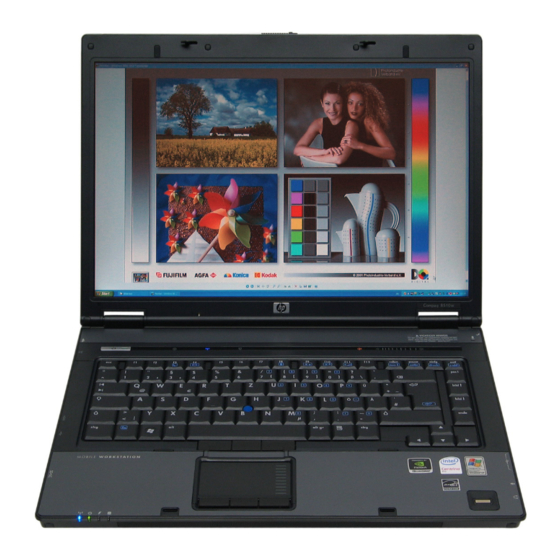
- Page 1 HP Compaq 8510w Mobile Workstation and HP Compaq 8510p Notebook PC Maintenance and Service Guide...
- Page 2 Logo is a trademark of its proprietor. The information contained herein is subject to change without notice. The only warranties for HP products and services are set forth in the express warranty statements accompanying such products and services. Nothing herein should be construed as constituting an additional warranty.
- Page 3 MSG revision history Revision Publication date Description ● May 2010 Updated commodities in the following location: Product description on page ● Updated AC adapter spare part numbers in the following locations: Miscellaneous parts on page Sequential part number listing on page 31 ●...
- Page 4 MSG revision history...
- Page 5 Safety warning notice WARNING! To reduce the possibility of heat-related injuries or of overheating the computer, do not place the computer directly on your lap or obstruct the computer air vents. Use the computer only on a hard, flat surface. Do not allow another hard surface, such as an adjoining optional printer, or a soft surface, such as pillows or rugs or clothing, to block airflow.
- Page 6 Safety warning notice...
-
Page 7: Table Of Contents
Table of contents 1 Product description ......................1 2 External component identification ..................7 Display components ......................... 7 Top components ........................8 Pointing devices ......................8 Buttons, switches, and fingerprint reader ..............9 Keys ........................10 Lights ........................11 Front components ........................13 Left-side components ....................... - Page 8 Packaging and transporting guidelines ........42 Workstation guidelines .............. 42 Equipment guidelines ..............43 Unknown user password ..................44 Component replacement procedures ..................45 Serial number ......................45 Computer feet ......................46 Battery ........................47 SIM ........................48 Display inverter ....................... 49 Hard drive ......................
- Page 9 6 Specifications ....................... 106 Computer specifications ......................106 15.4.-inch, WUXGA display specifications ................107 15.4-inch, WSXGA+ display specifications ................108 15.4-inch, WXGA display specifications ................. 109 Hard drive specifications ...................... 110 DVD±RW and CD-RW Double-Layer Combo Drive specifications ..........111 DVD/CD-RW Combo Drive specifications ................
- Page 10 Performing a recovery .................... 143 Performing a recovery from the recovery discs ........... 144 Performing a recovery from the hard drive ..........144 Initiating a recovery in Windows ..........144 Initiating a recovery from the hard drive recovery partition ... 144 Backup and recovery in Windows XP ..................
-
Page 11: Product Description
Description HP Compaq HP Compaq 8510w Mobile 8510p Workstation Notebook PC Product Name HP Compaq 8510w Mobile Workstation √ HP Compaq 8510p Notebook PC √ Processors Intel® Core™ 2 Duo processors T9500 2.6-GHz processor 6-MB L2 cache, 800- √ √... - Page 12 Category Description HP Compaq HP Compaq 8510w Mobile 8510p Workstation Notebook PC nVidia Quadro FX 570M graphics card √ (supports TurboCache) OpenGL driver support √ Panel All display assemblies include 3 wireless local √ √ area network (WLAN) antennae 15.4-inch WUXGA AntiGlare with 2 wireless √...
-
Page 13: Hard Drives
Category Description HP Compaq HP Compaq 8510w Mobile 8510p Workstation Notebook PC Hard drives Supports 9.5-mm, 2.5-inch hard drives √ √ Customer-accessible √ √ Serial ATA √ √ Supports the following drives: √ √ ● 250-GB, 7200-rpm ● 160-GB, 7200-rpm... - Page 14 Category Description HP Compaq HP Compaq 8510w Mobile 8510p Workstation Notebook PC S3/S4/S5 wake on LAN: AC - yes √ √ NIC power down technology √ √ Wireless Integrated WLAN options by way of wireless module: Three WLAN antennae built into display √...
-
Page 15: Power Requirements
Category Description HP Compaq HP Compaq 8510w Mobile 8510p Workstation Notebook PC USB (1) √ VGA (Dsub 15-pin) supporting 1600 × 1200 √ √ external resolution at 75-GHz (hot plug with auto-detect) 1394 √ 3-pin AC power √ √ Docking (Picabo), (Moseley), (K2) √... - Page 16 Category Description HP Compaq HP Compaq 8510w Mobile 8510p Workstation Notebook PC Windows XP Professional with Office 2007 √ √ Ready Windows XP Professional with Office 2007 √ Personal Restore Media: Windows Vista Business 32/64 √ √ Windows Vista Home 32 √...
-
Page 17: External Component Identification
External component identification Display components Item Component Function WWAN antennae (2) (select models only)* Send and receive wireless signals to communicate with WWANs. WLAN antenna (3) (select models only)* Send and receive wireless signals to communicate with WLANs. Ambient light sensor When activated, the sensor automatically adjusts the display brightness based on the surrounding lighting conditions. -
Page 18: Top Components
Top components Pointing devices Item Component Function Pointing stick (select models only) Moves the pointer and selects or activates items on the screen. Left pointing stick button (select models only) Functions like the left button on an external mouse. TouchPad Moves the pointer and selects or activates items on the screen. -
Page 19: Buttons, Switches, And Fingerprint Reader
Buttons, switches, and fingerprint reader Item Component Function Power button ● When the computer is off, press the button to turn on the computer. ● When the computer is on, press the button to shut down the computer. ● When the computer is in the Sleep state (Windows Vista) or in Standby (Windows XP), press the button briefly to exit the Sleep state or Standby. -
Page 20: Keys
Adjusts speaker volume. Slide your finger to the left to decrease volume and to the right to increase volume. Internal microphone Records sound. HP Fingerprint Sensor (finger print reader) Allows a fingerprint logon to Windows, instead of a password logon. Keys NOTE: Your computer may look slightly different from the illustration in this section. -
Page 21: Lights
Item Component Function ● Wireless lights (2)† On: An integrated wireless device, such as a wireless local area network (WLAN) device, the HP Broadband Wireless Module, and/or a Bluetooth® device, is on. ● Off: All wireless devices are off. ●... - Page 22 Item Component Function Info center light On: Info Center is on. Presentation light On: Presentation feature is on. Caps lock light On: Caps lock is on. Num lock light On: Num lock is on or the embedded numeric keypad is enabled.
-
Page 23: Front Components
Drive light ● Blinking green: The hard drive or optical drive is being accessed. ● Amber (select models only): HP 3D DriveGuard has temporarily parked the hard drive. Speakers Produce sound. Display release latch Opens the computer. -
Page 24: Left-Side Components
Left-side components Item Component Function Security cable slot Attaches an optional security cable to the computer. NOTE: The security cable is designed to act as a deterrent, but it may not prevent the computer from being mishandled or stolen. RJ-45 (network) jack Connects a network cable. -
Page 25: Rear Components
Rear components Item Component Function Power connector Connects an AC adapter. External monitor port Connects an external VGA monitor or projector. Right-side components Item Component Function Audio-out (headphone) jack Produces sound when connected to optional powered stereo speakers, headphones, ear buds, a headset, or television audio. -
Page 26: Bottom Components
Bottom components Item Component Function Hard drive bay Holds the hard drive. Accessory battery connector Connects an optional accessory battery. Battery release latches (2) Release the battery from the battery bay. Battery bay Holds the battery. SIM slot (select models only) Contains a SIM. -
Page 27: Illustrated Parts Catalog
Illustrated parts catalog Serial number location When ordering parts or requesting information, provide the computer serial number and model number located on the bottom of the computer. Serial number location... -
Page 28: Computer Major Components
Computer major components Chapter 3 Illustrated parts catalog... - Page 29 Item Description Spare part number Display assemblies for use with computer models equipped with WLAN and WWAN capability (includes 3 WLAN antenna transceivers and cables and 2 WWAN antenna transceivers and cables) 15.4-inch, WSXGA+ 452211-001 15.4-inch, WXGA 452210-001 Display assemblies for use with computer models equipped with only WLAN capability (includes 3 WLAN antenna transceivers and cables) 15.4-inch, WUXGA 452209-001...
- Page 30 Item Description Spare part number For use in Japan 452229-291 For use in Latin America 452229-161 For use in the Netherlands 452229-B31 For use in Norway 452229-091 For use in Portugal 452229-131 For use in Russia 452229-251 For use in Saudi Arabia 452229-171 For use in Slovakia 452229-231...
-
Page 31: Spare Part Number
For use with HP Compaq 8510w computer models (includes fingerprint reader board and 452224-001 cable) For use with HP Compaq 8510p computer models (does not include fingerprint reader board) 452223-001 Fingerprint reader board (not illustrated; includes fingerprint reader board cable) 455427-001... - Page 32 (11) WWAN modules HP ev2210 1xEVDO-A WWAN module 451131-001 HP hs2300 HSDPA WWAN module 448673-003 HP ev2200 1xEV-DO Broadband WWAN Module 399440-001 (12) WLAN modules Intel 802.11a/b/g/n WLAN modules: ● For use in Antigua and Barbuda, Argentina, Aruba, the Bahamas, Barbados, Bermuda,...
- Page 33 Item Description Spare part number ● For use in Afghanistan, Albania, Algeria, Andorra, Angola, Antigua and Barbuda, 441075-002 Argentina, Armenia, Aruba, Australia, Austria, Azerbaijan, the Bahamas, Bahrain, Bangladesh, Barbados, Belarus, Belgium, Belize, Benin, Bermuda, Bhutan, Bolivia, Bosnia and Herzegovina, Botswana, Brazil, the British Virgin Islands, Brunei, Bulgaria, Burkina Faso, Burundi, Cameroon, Cape Verde, the Central African Republic, Chad, Chile, China, Colombia, Comoros, the Congo, Costa Rica, Croatia, Cyprus, the Czech Republic, Denmark, Djibouti, Dominica, the Dominican Republic, East Timor, Ecuador,...
- Page 34 Item Description Spare part number ● For use in Afghanistan, Albania, Algeria, Andorra, Angola, Antigua & Barbuda, 441090-002 Argentina, Armenia, Aruba, Australia, Austria, Azerbaijan, the Bahamas, Bahrain, Bangladesh, Barbados, Belarus, Belgium, Belize, Benin, Bermuda, Bhutan, Bolivia, Bosnia & Herzegovina Botswana, Brazil, the British Virgin Islands, Brunei, Bulgaria, Burkina Faso, Burundi, Cambodia, Cameroon, Cape Verde, the Central African Republic, Chad, Chile, Colombia, Comoros, the Congo, Costa Rica, Croatia, Cyprus, the Czech Republic, Denmark, Djibouti, Dominica, the Dominican Republic, East Timor,...
- Page 35 Item Description Spare part number (14) Modem module NOTE: The modem module spare part kit does not include a modem module cable. The modem module cable is included in the Cable Kit, spare part number 452198-001. See Cable Kit on page 28 for more Cable Kit spare part number information.
- Page 36 Item Description Spare part number 250-GB, 7200-rpm 538972-001 160-GB, 7200-rpm 455954-001 (22) USB/audio board (includes USB board cable and audio board cable) 455426-001 (23) Broadcom Bluetooth modules (do not include Bluetooth module cable) NOTE: The Bluetooth module spare part kits do not include a Bluetooth module cable. The Bluetooth module cable is included in the Cable Kit, spare part number 452198-001.
-
Page 37: Plastics Kit
Plastics Kit Item Description Spare part number Plastics Kit: 452221-001 Memory module compartment cover (includes one captive screw, secured by a C-clip) Hard drive cover (includes 2 captive screws, secured by C-clips) Base enclosure screw covers (2) PC Card slot bezel Computer feet (10) Plastics Kit... -
Page 38: Cable Kit
Cable Kit Item Description Spare part number Cable Kit: 452198-001 Bluetooth module cable RJ-11 connector cable Microphone Modem module cable Chapter 3 Illustrated parts catalog... -
Page 39: Mass Storage Devices
Mass storage devices Item Description Spare part number Optical drives (include bezel) DVD±RW and CD-RW Super Multi Double-Layer Combo Drive with LightScribe 443903-001 DVD±RW and CD-RW Super Multi Double-Layer Combo Drive 443904-001 Blu-Ray DVD-RW Drive 452220-001 DVD/CD-RW Combo Drive 443901-001 DVD-ROM Drive 443902-001 Hard drives (include bracket ) -
Page 40: Miscellaneous Parts
Smart Adapter 90-W, non-PFC for use in India 463956-001 External MultiBay II 366143-001 External MultiBay II power cable and stand 366144-001 HP Extended Life Battery 367456-001 MultiBay 8X DVD-ROM Drive 373314-001 MultiBay 24X DVD/CD-RW Combo Drive 373315-001 Nylon carrying case 325814-001 USB 1.1 diskette drive... -
Page 41: Sequential Part Number Listing
Description Spare part number For use the United States 246959-001 Screw Kit 452222-001 ● Phillips PM2.5×4.0 screw ● Phillips PM2.0×10.0 screw ● Phillips PM2.0×5.0 captive screw ● Phillips PM2.0×5.0 screw ● Phillips PM2.0×4.0 screw ● Phillips PM2.0×3.0 screw ● Phillips PM2.0×2.0 broad head screw ●... - Page 42 Cable Kit on page 28 for more Cable Kit spare part number information. 399440-001 HP ev2200 1xEV-DO Broadband WWAN Module 409280-004 Intel 802.11b/g WLAN module for use in Thailand 413706-001 Thermal Material Kit for use in all countries and regions except Japan and Asia Pacific countries and regions 441075-001 Broadcom 802.11a/b/g WLAN module for use in Canada, Cayman Islands, Guam, Puerto Rico, the U.S.
- Page 43 Spare part Description number 441086-001 Intel 802.11a/b/g/n WLAN module for use in Antigua and Barbuda, Argentina, Aruba, the Bahamas, Barbados, Bermuda, Brunei, Canada, the Cayman Islands, Chile, Colombia, Costa Rica, the Dominican Republic, Ecuador, El Salvador, Guam, Guatemala, Haiti, Honduras, Hong Kong, India, Indonesia, Malaysia, Mexico, Panama, Paraguay, Peru, Saudi Arabia, Taiwan, Uruguay, the United States, Venezuela, and Vietnam 441086-002...
- Page 44 Intel Core Duo T7500 2.2-GHz processor (4-MB L2 cache, 800-MHz FSB) 446894-001 Intel Core Duo T7700 2.4-GHz processor (4-MB L2 cache, 800-MHz FSB) 448673-003 HP hs2300 HSDPA WWAN module 448675-004 Intel 802.11b/g WLAN module for use in Japan 450066-001 Broadcom Bluetooth module for use only in Japan and Asia Pacific countries and regions NOTE: The Bluetooth module spare part kits do not include a Bluetooth module cable.
- Page 45 Screw Kit 452223-001 Top cover for use with HP Compaq 8510p computer models (does not include fingerprint reader board) 452224-001 Top cover for use with HP Compaq 8510w computer models (includes fingerprint reader board and cable) 452225-001 Speaker assembly 452226-001...
- Page 46 Spare part Description number 452228-291 Keyboard without pointing stick for use in Japan (includes keyboard cable) 452228-A41 Keyboard without pointing stick for use in Belgium (includes keyboard cable) 452228-AB1 Keyboard without pointing stick for use in Taiwan (includes keyboard cable) 452228-AD1 Keyboard without pointing stick for use in South Korea (includes keyboard cable) 452228-B31...
- Page 47 Spare part Description number 452229-AB1 Keyboard with pointing stick for use in Taiwan (includes keyboard and pointing stick cables) 452229-AD1 Keyboard with pointing stick for use in South Korea (includes keyboard and pointing stick cables) 452229-B31 Keyboard with pointing stick for use in the Netherlands and Europe (includes keyboard and pointing stick cables) 452229-B71 Keyboard with pointing stick for use in Sweden (includes keyboard and pointing stick cables)
- Page 48 Spare part Description number 481537-001 System board for use with computer models equipped only with WLAN capability with T8xxx and T9xxx processors 501228-001 RTC battery 509999-001 System board for use with computer models equipped only with WLAN capability only in Russia and the People's Republic of China 510000-001 System board for use with computer models equipped with WLAN and WWAN capability only in Russia and...
-
Page 49: Removal And Replacement Procedures
Removal and replacement procedures Preliminary replacement requirements Tools required You will need the following tools to complete the removal and replacement procedures: ● Flat-bladed screwdriver ● Magnetic screwdriver ● Hex metric 5.0-mm nut driver ● Phillips P0 and P1 screwdrivers ●... -
Page 50: Cables And Connectors
Cables and connectors CAUTION: When servicing the computer, be sure that cables are placed in their proper locations during the reassembly process. Improper cable placement can damage the computer. Cables must be handled with extreme care to avoid damage. Apply only the tension required to unseat or seat the cables during removal and insertion. -
Page 51: Grounding Guidelines
Grounding guidelines Electrostatic discharge damage Electronic components are sensitive to electrostatic discharge (ESD). Circuitry design and structure determine the degree of sensitivity. Networks built into many integrated circuits provide some protection, but in many cases, ESD contains enough power to alter device parameters or melt silicon junctions. -
Page 52: Packaging And Transporting Guidelines
Packaging and transporting guidelines Follow these grounding guidelines when packaging and transporting equipment: ● To avoid hand contact, transport products in static-safe tubes, bags, or boxes. ● Protect ESD-sensitive parts and assemblies with conductive or approved containers or packaging. ● Keep ESD-sensitive parts in their containers until the parts arrive at static-free workstations. -
Page 53: Equipment Guidelines
Equipment guidelines Grounding equipment must include either a wrist strap or a foot strap at a grounded workstation. ● When seated, wear a wrist strap connected to a grounded system. Wrist straps are flexible straps with a minimum of one megohm ±10% resistance in the ground cords. To provide proper ground, wear a strap snugly against the skin at all times. -
Page 54: Unknown User Password
Unknown user password If the computer you are servicing has an unknown user password, follow these steps to clear the password: NOTE: These steps also clear CMOS. Shut down the computer. If you are unsure whether the computer is off or in Hibernation, turn the computer on, and then shut it down through the operating system. -
Page 55: Component Replacement Procedures
Make special note of each screw and screw lock size and location during removal and replacement. Serial number Report the computer serial number to HP when requesting information or ordering spare parts. The serial number is located on the bottom of the computer. Component replacement procedures... -
Page 56: Computer Feet
Computer feet The computer feet are adhesive-backed rubber pads. The feet are included in the Plastics Kit, spare part number 452221-001. There are 10 rubber feet that attach to the base enclosure in the locations illustrated below. Chapter 4 Removal and replacement procedures... -
Page 57: Battery
Battery Description Spare part number 8-cell, 5.10-Ah (73-Wh) Li-ion battery 452195-001 8-cell, 5.10-Ah (73-Wh) Li-ion battery only for use in Thailand 464474-001 8-cell, 5.10-Ah (73-Wh) Li-ion battery only for use in Japan 534064-001 Before disassembling the computer, follow these steps: Shut down the computer. -
Page 58: Sim
NOTE: This section applies only to computer models with WWAN capability. NOTE: If there is a SIM inserted in the SIM slot, it must be removed before disassembling the computer. Be sure that the SIM is reinserted in the SIM slot after reassembling the computer. Before removing the SIM, follow these steps: Shut down the computer. -
Page 59: Display Inverter
Display inverter NOTE: If it has been determined that the display inverter is the component that must be replaced to complete the computer repair, the display assembly does not have to be removed. Follow the procedures in this section to replace the display inverter. For information on replacing the display assembly and the display hinges, see Display assembly on page Description... - Page 60 Release the display bezel bottom edge (3) from the display assembly. Remove the two Torx T8M2.5×6.0 screws (1) that secure the display inverter to the display enclosure. Release the inverter (2) from the display enclosure as far as the display panel cable and backlight cable allow.
-
Page 61: Hard Drive
Hard drive NOTE: All hard drive spare part kits include a hard drive bracket. Description Spare part number 250-GB, 7200-rpm hard drive 538972-001 160-GB, 7200-rpm hard drive 455954-001 Before disassembling the computer, follow these steps: Shut down the computer. If you are unsure whether the computer is off or in Hibernation, turn the computer on, and then shut it down through the operating system. - Page 62 Remove the hard drive (4) from the hard drive bay. If it is necessary to replace the hard drive bracket, remove the two Phillips PM3.0×4.0 hard drive bracket screws (1) from each side of the hard drive. Lift the bracket (2) straight up to remove it from the hard drive. Reverse this procedure to reassemble and install the hard drive.
-
Page 63: Bluetooth Module
Bluetooth module NOTE: The Bluetooth module spare part kits do not include a Bluetooth module cable. The Bluetooth module cable is included in the Cable Kit, spare part number 452198-001. See Cable Kit on page 28 for more Cable Kit spare part number information. Description Spare part number For use in all countries and regions except Japan and Asia Pacific countries and regions... -
Page 64: Optical Drive
Optical drive NOTE: All optical drive spare part kits include an optical drive bezel. Description Spare part number DVD±RW and CD-RW Super Multi Double-Layer Combo Drive with LightScribe 443903-001 DVD±RW and CD-RW Super Multi Double-Layer Combo Drive 443904-001 Blu-Ray DVD-RW Drive 452220-001 DVD/CD-RW Combo Drive 443901-001... - Page 65 If it is necessary to replace the optical drive bracket, position the optical drive with the rear toward you. Remove the two Phillips PM2.0×3.0 screws (1) that secure the optical drive bracket to the optical drive. Remove the optical drive bracket (2). Reverse this procedure to install an optical drive.
-
Page 66: Memory Module
Memory module Description Spare part number 4096-MB (PC2-5300, 667-MHz, DDR2) 598855-001 2048-MB (PC2-5300, 667-MHz, DDR2) 598858-001 1024-MB (PC2-5300, 667-MHz, DDR2) 598861-001 512-MB (PC2-5300, 667-MHz, DDR2) 598833-001 Before removing the memory module, follow these steps: Shut down the computer. If you are unsure whether the computer is off or in Hibernation, turn the computer on, and then shut it down through the operating system. - Page 67 Remove the memory module (2) by pulling the module away from the slot at an angle. NOTE: Memory modules are designed with a notch (3) to prevent incorrect installation into the memory module slot. Reverse this procedure to install a memory module. Component replacement procedures...
-
Page 68: Keyboard
Keyboard For use in: Spare part number For use in: Spare part number Keyboards with pointing stick (includes pointing stick cable): Belgium 455529-A41 The Netherlands and Europe 455529-021 Brazil 455529-201 Norway 455529-091 The Czech Republic 455529-221 Portugal 455529-131 Denmark 455529-081 Russia 455529-251 France... - Page 69 For use in: Spare part number For use in: Spare part number Keyboards without pointing stick: Belgium 455528-A41 The Netherlands and Europe 455528-021 Brazil 455528-201 Norway 455528-091 The Czech Republic 455528-221 Portugal 455528-131 Denmark 455528-081 Russia 455528-251 France 455528-051 Saudi Arabia 455528-171 French Canada 455528-121...
- Page 70 Loosen the two Phillips PM2.5×9.0 captive screws that secure the keyboard to the computer. Turn the computer display-side up, with the front toward you. Open the computer as far as possible. Slide the four keyboard retention tabs (1) toward you. The tabs are located between the keys, between the keys, between the keys, and between the...
-
Page 71: Wwan Module
451131-001 HP hs2300 HSDPA WWAN module 448673-003 HP ev2200 1xEV-DO Broadband WWAN Module 399440-001 Before removing the WWAN module, follow these steps: Shut down the computer. If you are unsure whether the computer is off or in Hibernation, turn the computer on, and then shut it down through the operating system. - Page 72 Remove the WWAN module: Disconnect the WWAN antenna cables (1) from the terminals on the WWAN module. NOTE: The red WWAN antenna cable is connected to the WWAN module “Main” terminal. The blue WWAN antenna cable is connected to the WWAN module “Aux” terminal. Remove the two Phillips PM2.5×4.0 screws (2) that secure the WWAN module to the computer.
-
Page 73: Fan
Description Spare part number 452199-001 Before removing the fan, follow these steps: Shut down the computer. If you are unsure whether the computer is off or in Hibernation, turn the computer on, and then shut it down through the operating system. Disconnect all external devices connected to the computer. -
Page 74: Heat Sink
configurations, battery fast charging, and software requirements. Exhaust air is displaced through the ventilation grill located on the left side of the computer. Heat sink Description Spare part number Heat sink (includes a heat sink clip and replacement thermal material) 452227-001 Thermal Material Kits For use in all countries or regions except Japan and Asia countries and regions... - Page 75 Remove the heat sink retention clip (3). Lift the right side of the heat sink (1) to disengage it from the graphics card. Remove the heat sink (2) by sliding it to the right. NOTE: The thermal material must be thoroughly cleaned from the surfaces of the heat sink (1) and (3), the processor (2), and graphics system component (4) each time the heat sink is removed.
- Page 76 Reverse this procedure to install the heat sink. Chapter 4 Removal and replacement procedures...
-
Page 77: Processor
Processor NOTE: All processor spare part kits include replacement thermal material. The Thermal Material Kit is also available using spare part numbers 413706-001 (for use in all countries or regions except Japan and Asia countries and regions) and 445853-001 (for use only in Japan and Asia Pacific countries and regions). -
Page 78: Graphics Card
Lift the processor (2) straight up and remove it. NOTE: The gold triangle (3) on the processor must be aligned with the triangle (4) embossed on the processor slot when you install the processor. Reverse this procedure to install the processor. Graphics card NOTE: All graphics card spare part kits include replacement thermal material. - Page 79 Remove the battery (see Battery on page 47). Remove the following components: Keyboard (see Keyboard on page Fan (see Fan on page Heat sink (see Heat sink on page Remove the graphics card: Remove the two Phillips PM2.0×3.0 screws (1) that secure the graphics card to the computer. (The edge of the board opposite the graphics card slot rises away from the computer.) Remove the graphics card (2) by sliding it away from the graphics card slot at an angle.
-
Page 80: Touchpad
TouchPad NOTE: All TouchPad spare part kits include a TouchPad cable. The TouchPad cable is also included in the Cable Kit, spare part number 452198-001. Description Spare part number With 3 TouchPad buttons and 3 pointing stick buttons for use with keyboards with pointing stick 455969-001 With 2 TouchPad buttons for use with keyboards without pointing stick 454248-001... - Page 81 Release the TouchPad (2) by sliding it toward the display. Disconnect the TouchPad cable (1) from the system board. Remove the TouchPad (2). Reverse this procedure to install the TouchPad. Component replacement procedures...
-
Page 82: Wlan Module
WLAN module CAUTION: The WLAN module and the WWAN module are not interchangeable. Description Spare part number Intel 802.11a/b/g/n WLAN modules: ● For use in Antigua and Barbuda, Argentina, Aruba, the Bahamas, Barbados, Bermuda, 441086-001 Brunei, Canada, the Cayman Islands, Chile, Colombia, Costa Rica, the Dominican Republic, Ecuador, El Salvador, Guam, Guatemala, Haiti, Honduras, Hong Kong, India, Indonesia, Malaysia, Mexico, Panama, Paraguay, Peru, Saudi Arabia, Taiwan, Uruguay, the United States, Venezuela, and Vietnam... - Page 83 Description Spare part number ● For use in Antigua & Barbuda, Argentina, Aruba, the Bahamas, Barbados, Bermuda, Brunei, 441082-001 Canada, the Cayman Islands, Chile, Colombia, Costa Rica, the Dominican Republic, Ecuador, El Salvador, Guam, Guatemala, Haiti, Honduras, Hong Kong, India, Indonesia, Malaysia, Mexico, Panama, Paraguay, Peru, Saudi Arabia, Taiwan, the United States, Uruguay, Venezuela, and Vietnam ●...
- Page 84 Before removing the WLAN module, follow these steps: Shut down the computer. If you are unsure whether the computer is off or in Hibernation, turn the computer on, and then shut it down through the operating system. Disconnect all external devices connected to the computer. Disconnect the power from the computer by first unplugging the power cord from the AC outlet and then unplugging the AC adapter from the computer.
-
Page 85: Switch Cover
Switch cover Description Spare part number Switch cover (includes LED board and cable) 452226-001 Before removing the switch cover, follow these steps: Shut down the computer. If you are unsure whether the computer is off or in Hibernation, turn the computer on, and then shut it down through the operating system. - Page 86 Lift the switch cover (2) up and back. Release the ZIF connector (1) to which the LED board cable is attached, and disconnect the LED board cable (2) from the connector. Chapter 4 Removal and replacement procedures...
- Page 87 Remove the switch cover. Reverse this procedure to install switch cover. Component replacement procedures...
-
Page 88: Rtc Battery
RTC battery NOTE: Removing the RTC battery and leaving it uninstalled for 5 or more minutes causes all passwords and CMOS settings to be cleared. Description Spare part number RTC battery 501228-001 Before removing the RTC battery, follow these steps: Shut down the computer. -
Page 89: Display Assembly
Display assembly Description Spare part number Display assemblies for use with computer models equipped with WLAN and WWAN capability (includes 3 WLAN antenna transceivers and cables and 2 WWAN antenna transceivers and cables) 15.4-inch, WSXGA+ 452211-001 15.4-inch, WXGA 452210-001 Display assemblies for use with computer models equipped with only WLAN capability (includes 3 WLAN antenna transceivers and cables) 15.4-inch, WUXGA 452209-001... - Page 90 Remove the wireless antenna cables from the clips (2) and (3) and routing channels (4) built into the top cover. Remove the following screws: (1) Two Torx T8M2.5×9.0 screws (2) One Phillips PM2.5×4.0 screw (3) Two Phillips PM2.0×2.0 screws Position the computer with the rear panel toward you. Remove the four Torx T8M2.5×9.0 screws (1) that secure the display assembly to the computer.
- Page 91 Lift the display assembly (2) straight up and remove it. CAUTION: When installing the display assembly, be sure that the 4 wireless antenna cables routed out of the display right hinge are routed and arranged properly. Each antenna cable has an exposed section of cable and a metallic grounding sleeve (1).
- Page 92 If it is necessary to replace the display bezel or display hinges, remove the following: (1) Four rubber screw covers on the display bezel top edge (2) Two rubber screw covers on the display bezel bottom edge (3) Four Torx T8M2.5×6.0 screws on the display bezel top edge (4) Two Torx T8M2.5×7.0 screws on the display bezel bottom edge NOTE: Display inverter on page 49...
- Page 93 Remove the display panel (2). Remove the four Phillips PM2.0×4.0 screws (1) that secure each display hinge to the display panel. Remove the display hinges (2). The left and right display hinges are available using spare part number 452213-001. Reverse this procedure to reassemble and install the display assembly. Component replacement procedures...
-
Page 94: Top Cover
Top cover Description Spare part number For use with HP Compaq 8510w computer models (includes fingerprint reader board and cable) 452224-001 For use with HP Compaq 8510p computer models (does not include fingerprint reader board) 452223-001 Before removing the top cover, follow these steps: Shut down the computer. - Page 95 Remove the ten Torx T8M2.5×9.0 screws (2) that secure the top cover to the base enclosure. Turn the computer right-side up, with the front toward you. Disconnect the fingerprint reader board cable (1) from the system board. Remove the two Torx T8M2.5×7.0 screws (2) and the four Phillips PM2.5×3.0 screws (3) that secure the top cover to the computer.
- Page 96 Remove the top cover (3). If it is necessary to replace the microphone, turn the top cover upside down with the front toward you. Remove the microphone cable from the clips (1) built into the top cover. Remove the microphone receiver (2) from the clip (3) built into the top cover. Reverse this procedure to install the top cover.
-
Page 97: Speaker Assembly
Speaker assembly Description Spare part number Speaker assembly 452225-001 Before removing the speaker assembly, follow these steps: Shut down the computer. If you are unsure whether the computer is off or in Hibernation, turn the computer on, and then shut it down through the operating system. Disconnect all external devices connected to the computer. - Page 98 Remove the speaker assembly (3) from the base enclosure. Reverse this procedure to install the speaker assembly. Chapter 4 Removal and replacement procedures...
-
Page 99: Modem Module
Modem module NOTE: The modem module spare part kit does not include a modem module cable. The modem module cable is included in the Cable Kit, spare part number 452198-001. See Cable Kit on page 28 for more Cable Kit spare part number information. Description Spare part number Modem module for use in all countries and regions except Australia and New Zealand... -
Page 100: System Board And System Board Frame
Disconnect the modem module cable (3) from the system board. Reverse this procedure to install the modem module. System board and system board frame NOTE: All system board spare part kits include replacement thermal material. The Thermal Material Kit is also available using spare part numbers 413706-001 (for use in all countries or regions except Japan and Asia countries and regions) and 445853-001 (for use only in Japan and Asia Pacific countries and regions). - Page 101 Before removing the system board, follow these steps: Shut down the computer. If you are unsure whether the computer is off or in Hibernation, turn the computer on, and then shut it down through the operating system. Disconnect all external devices connected to the computer. Disconnect the power from the computer by first unplugging the power cord from the AC outlet and then unplugging the AC adapter from the computer.
- Page 102 Remove the system board: Disconnect the following cables from the system board: (1) RJ-11 connector cable (2) USB board cable (3) Audio board cable (4) Bluetooth module cable Position the base enclosure with the rear panel toward you. Remove the four black Phillips PM2.5×7.0 screws (1) and the four silver Phillips PM2.5×7.0 screws (2) that secure the system board frame to the base enclosure.
- Page 103 Lift the system board (3) and frame straight up and remove them from the base enclosure. NOTE: When removing the system board and frame, be sure that the USB/audio board cables (4) route cleanly through the opening in the system board frame. Remove the silver Phillips PM2.5×7.0 screw (1) and the two HM5.0×9.0 screw locks (2) that secure the system board to the system board frame.
-
Page 104: Rj-11 Connector Cable
Remove the system board (3) from the system board frame by sliding it forward. Reverse the preceding procedure to install the system board. RJ-11 connector cable NOTE: The RJ-11 connector cable is included in the Cables Kit, spare part number 452198-001. Before removing the RJ-11 connector cable, follow these steps: Shut down the computer. -
Page 105: Pc Card Assembly
Speaker assembly (see Speaker assembly on page Modem module (see Modem module on page System board (see System board and system board frame on page Remove the RJ-11 connector cable: Remove the RJ-11 connector (1) from the clip built into the base enclosure. Remove the RJ-11 connector cable from the clips and routing channel (2) built into the base enclosure. - Page 106 Remove the battery (see Battery on page 47). Remove the following components: Hard drive (see Hard drive on page Optical drive (see Optical drive on page Keyboard (see Keyboard on page Fan (see Fan on page Heat sink (see Heat sink on page Switch cover (see Switch cover on page TouchPad (see...
-
Page 107: Usb/Audio Board
Remove the PC Card assembly (2). Reverse this procedure to install the PC Card assembly. USB/audio board Description Spare part number USB/audio board (includes USB cable and audio cable) 455426-001 Before removing the USB/audio board, follow these steps: Shut down the computer. If you are unsure whether the computer is off or in Hibernation, turn the computer on, and then shut it down through the operating system. - Page 108 Display assembly (see Display assembly on page Top cover (see Top cover on page Speaker assembly (see Speaker assembly on page Modem module (see Modem module on page System board (see System board and system board frame on page Remove the USB/audio board: Remove the two Phillips PM2.5×4.0 screws (1) that secure the USB/audio board to the base enclosure.
-
Page 109: Computer Setup
Computer Setup Starting Computer Setup Computer Setup is a preinstalled, ROM-based utility that can be used even when the operating system is not working or will not load. NOTE: Some of the Computer Setup menu items listed in this guide may not be supported by your computer. -
Page 110: Using Computer Setup
Using Computer Setup Navigating and selecting in Computer Setup The information and settings in Computer Setup are accessed from the File, Security, Diagnostics, and System Configuration menus. Open Computer Setup by turning on or restarting the computer, and then pressing while the "F10 = ROM Based Setup"... -
Page 111: Computer Setup Menus
Computer Setup menus The menu tables in this section provide an overview of Computer Setup options. NOTE: Some of the Computer Setup menu items listed in this chapter may not be supported by your computer. File menu Select To do this ●... -
Page 112: Security Menu
Security menu Select To do this Setup password Enter, change, or delete a setup password. Power-On password Enter, change, or delete a power-on password. ● Password options Enable/disable stringent security. ● Enable/disable password requirement on computer restart. ● DriveLock passwords Enable/disable DriveLock on any computer hard drive and on optional MultiBay hard drives. -
Page 113: System Configuration Menu
System Configuration menu NOTE: Some of the listed System Configuration options may not be supported by your computer. Select To do this Language (or press f2) Change the Computer Setup language. Boot options ● Set f9, f10, and delay when starting up. ●... - Page 114 ● Enable/disable SATA Native Mode. ● Enable/disable Dual Core CPU. ● Enable/disable Secondary Battery Fast Charge. ● Choose Bit-shift or LBA assisted HDD Translation Mode. ● Enable/disable Windows direct application launcher. ● Enable/disable HP Lockout. 104 Chapter 5 Computer Setup...
- Page 115 Select To do this Built-In Device Options ● Enable/disable embedded WWAN Device Radio. ● Enable/disable embedded WLAN Device Radio. ● Enable/disable embedded Bluetooth® Device Radio. ● Enable/disable LAN/WLAN Switching. When enabled, switches to a WLAN when a LAN is either unavailable or disconnected. ●...
-
Page 116: Specifications
Specifications Computer specifications Metric U.S. Dimensions Length 26.0 cm 10.24 in Width 35.7 cm 14.00 in Height (front to rear) 2.8 to 3.4 cm 1.10 to 1.34 in Weight (equipped with optical drive, 8-cell battery, one 2.77 kg 6.1 lbs 512-MB memory module, pointing stick, and TouchPad) Input power Operating voltage... -
Page 117: 15.4.-Inch, Wuxga Display Specifications
Metric U.S. Operating 0.75 g zero-to-peak, 10 Hz to 500 Hz, 0.25 oct/min sweep rate Nonoperating 1.50 g zero-to-peak, 10 Hz to 500 Hz, 0.5 oct/min sweep rate NOTE: Applicable product safety standards specify thermal limits for plastic surfaces. The computer operates well within this range of temperatures. -
Page 118: Inch, Wsxga+ Display Specifications
15.4-inch, WSXGA+ display specifications Metric U.S. Dimensions Height 20.7 cm 8.15 in Width 33.1 cm 13.03 in Diagonal 39.1 cm 15.39 in Number of colors Up to 16.8 million Contrast ratio 200:1 (typical) Brightness 180 nits (typical) Pixel resolution Pitch 0.197 ×... -
Page 119: 15.4-Inch, Wxga Display Specifications
15.4-inch, WXGA display specifications Metric U.S. Dimensions Height 20.7 cm 8.15 in Width 33.1 cm 13.03 in Diagonal 39.1 cm 15.39 in Number of colors Up to 16.8 million Contrast ratio 200:1 (typical) Brightness 180 nits (typical) Pixel resolution Pitch 0.197 ×... -
Page 120: Hard Drive Specifications
Hard drive specifications 250-GB* 160-GB* Dimensions Height 9.5 mm 9.5 mm Width 70 mm 70 mm Weight 101 g 101 g Interface type SATA SATA Transfer rate 100 MB/sec 100 MB/sec Security ATA security ATA security Seek times (typical read, including setting) Single track 3 ms 3 ms... -
Page 121: Dvd±Rw And Cd-Rw Double-Layer Combo Drive Specifications
DVD±RW and CD-RW Double-Layer Combo Drive specifications Applicable disc Read: Write: CD-DA, CD+(E)G, CD-MIDI, CD-TEXT, CD-ROM, CD-R and CD-RW CD-ROM XA, MIXED MODE CD, CD-I, CD-I DVD+R, DVD+RW, DVD-R, DVD- Bridge (Photo-CD, Video CD), Multisession CD RW, DVD-RAM (Photo-CD, CD-EXTRA, Portfolio, CD-R, CD-RW), CD-R, CD-RW, DVD-ROM (DVD-5, DVD-9, DVD-10, DVD-18), DVD-R, DVD-RW, DVD+R, DVD+RW, DVD-RAM... -
Page 122: Dvd/Cd-Rw Combo Drive Specifications
DVD/CD-RW Combo Drive specifications Applicable disc Read: Write: CD-DA, CD+(E)G, CD-MIDI, CD-TEXT, CD-ROM, CD-R and CD-RW CD-ROM XA, MIXED MODE CD, CD-I, CD-I Bridge (Photo-CD, Video CD), Multisession CD (Photo-CD, CD-EXTRA, Portfolio, CD-R, CD-RW), CD-R, CD-RW, DVD-ROM (DVD-5, DVD-9, DVD-10, DVD-18), DVD-R, DVD-RW, DVD+R, DVD+RW, DVD-RAM Center hole diameter 1.5 cm (0.59 in) -
Page 123: Dvd-Rom Drive
DVD-ROM Drive Applicable disc DVD-ROM (DVD-5, DVD-9, DVD-10, DVD-18, CD-ROM (Mode 1 and 2), CD Digital Audio, CD-XA ready (Mode 2, Form 1 and Form 2), CD-I (Mode 2, Form 1 and Form 2), CD-R, CD-RW, Photo CD (single and multisession), CD-Bridge Center hole diameter 1.5 cm (0.59 in) Disc diameter... -
Page 124: System Dma Specifications
System DMA specifications Hardware DMA System function DMA0 Not applicable DMA1* Not applicable DMA2* Not applicable DMA3 Not applicable DMA4 Direct memory access controller DMA5* Available for PC Card DMA6 Not assigned DMA7 Not assigned *PC Card controller can use DMA 1, 2, or 5. 114 Chapter 6 Specifications... -
Page 125: System Interrupt Specifications
System interrupt specifications Hardware IRQ System function IRQ0 System timer IRQ1 Standard 101-/102-Key or Microsoft® Natural Keyboard IRQ2 Cascaded IRQ3 Intel 82801DB/DBM USB2 Enhanced Host Controller—24CD IRQ4 COM1 IRQ5* Conexant AC—Link Audio Intel 82801DB/DBM SMBus Controller—24C3 Data Fax Modem with SmartCP IRQ6 Diskette drive IRQ7*... -
Page 126: System I/O Address Specifications
System I/O address specifications I/O address (hex) System function (shipping configuration) 000 - 00F DMA controller no. 1 010 - 01F Unused 020 - 021 Interrupt controller no. 1 022 - 024 Opti chipset configuration registers 025 - 03F Unused 02E - 02F 87334 “Super I/O”... - Page 127 I/O address (hex) System function (shipping configuration) JoyStick (decoded in ESS1688) 202 - 21F Unused 220 - 22F Entertainment audio 230 - 26D Unused 26E - 26 Unused 278 - 27F Unused 280 - 2AB Unused 2A0 - 2A7 Unused 2A8 - 2E7 Unused 2E8 - 2EF...
-
Page 128: System Memory Map Specifications
System memory map specifications Size Memory address System function 640 KB 00000000-0009FFFF Base memory 128 KB 000A0000-000BFFFF Video memory 48 KB 000C0000-000CBFFF Video BIOS 160 KB 000C8000-000E7FFF Unused 64 KB 000E8000-000FFFFF System BIOS 15 MB 00100000-00FFFFFF Extended memory 58 MB 04800000-07FFFFFF Super extended memory 58 MB... -
Page 129: Screw Listing
Screw listing This section provides specification and reference information for the screws and screw locks used in the computer. All screws listed in this section are available in the Screw Kit, spare part number 452222-001. -
Page 130: Phillips Pm2.0×5.0 Captive Screw
Phillips PM2.0×5.0 captive screw Color Quantity Length Thread Head diameter Black 5.0 mm 2.0 mm 4.5 mm Where used: (1) Two screws that secure the hard drive cover to the computer (screws are captured on the cover by C-clips) (2) One screw that secures the memory module compartment cover to the computer (screw is captured on the cover by a C-clip) 120 Chapter 7 Screw listing... -
Page 131: Phillips Pm2.0×11.0 Captive Screw
Phillips PM2.0×11.0 captive screw Color Quantity Length Thread Head diameter Silver 11.0 mm 2.0 mm 5.0 mm Where used: One screw that secures the hard drive to the computer Phillips PM2.0×11.0 captive screw 121... -
Page 132: Phillips Pm3.0×4.0 Screw
Phillips PM3.0×4.0 screw Color Quantity Length Thread Head diameter Silver 4.0 mm 3.0 mm 5.0 mm Where used: 4 screws that secure the hard drive bracket to the hard drive 122 Chapter 7 Screw listing... -
Page 133: Torx T8M2.5×9.0 Screw
Torx T8M2.5×9.0 screw Color Quantity Length Thread Head diameter Black 9.0 mm 2.5 mm 5.0 mm Where used: (1) One screw that secures the optical drive to the computer (2) One screw that secures the TouchPad to the computer (3) One screw that secures the switch cover to the computer Torx T8M2.5×9.0 screw 123... - Page 134 Where used: 2 screws that secure the display assembly to the computer Where used: 4 screws that secure the display assembly to the computer Where used: 10 screws that secure the top cover to the base enclosure 124 Chapter 7 Screw listing...
-
Page 135: Silver Phillips Pm2.0×3.0 Screw
Silver Phillips PM2.0×3.0 screw Color Quantity Length Thread Head diameter Silver 3.0 mm 2.0 mm 4.5 mm Where used: 2 screws that secure the optical drive bracket to the optical drive Where used: 6 screws that secure the heat sink to the system board Silver Phillips PM2.0×3.0 screw 125... - Page 136 Where used: 2 screws that secure the graphics card to the system board 126 Chapter 7 Screw listing...
-
Page 137: Phillips Pm2.5×9.0 Captive Screw
Phillips PM2.5×9.0 captive screw Color Quantity Length Thread Head diameter Black 9.0 mm 2.5 mm 5.0 mm Where used: 2 captive screws that secure the keyboard to the computer Phillips PM2.5×9.0 captive screw 127... -
Page 138: Phillips Pm2.0×6.0 Screw
Phillips PM2.0×6.0 screw Color Quantity Length Thread Head diameter Silver 6.0 mm 2.0 mm 4.5 mm Where used: 2 screws that secure the fan to the base enclosure 128 Chapter 7 Screw listing... -
Page 139: Phillips Pm2.5×4.0 Screw
Phillips PM2.5×4.0 screw Color Quantity Length Thread Head diameter Black 4.0 mm 2.5 mm 5.0 mm Where used: (1) Two screws that secure the WWAN module to the computer (2) Two screws that secure the WLAN module to the computer Phillips PM2.5×4.0 screw 129... - Page 140 Where used: One screw that secures the display assembly to the computer Where used: 3 screws that secure the speaker assembly to the base enclosure Where used: 2 screws that secure the modem module to the system board 130 Chapter 7 Screw listing...
-
Page 141: Phillips Pm2.0×2.0 Screw
Phillips PM2.0×2.0 screw Color Quantity Length Thread Head diameter Black 2.0 mm 2.0 mm 4.5 mm Where used: 3 screws that secure the switch cover to the computer Where used: 2 screws that secure the display assembly to the computer Phillips PM2.0×2.0 screw 131... -
Page 142: Torx T8M2.5×6.0 Screw
Torx T8M2.5×6.0 screw Color Quantity Length Thread Heat width Black 6.0 mm 2.5 mm 5.0 mm Where used: 4 screws that secure the display bezel top edge to the display assembly Where used: (1) Two screws that secure the display inverter to the display enclosure (2) Four screws that secure the display panel to the display enclosure 132 Chapter 7 Screw listing... -
Page 143: Torx T8M2.5×7.0 Screw
Torx T8M2.5×7.0 screw Color Quantity Length Thread Head diameter Silver 7.0 mm 2.5mm 5.0 mm Where used: 2 screws that secure the display bezel bottom edge to the display enclosure Torx T8M2.5×7.0 screw 133... -
Page 144: Phillips Pm2.0×4.0 Screw
Phillips PM2.0×4.0 screw Color Quantity Length Thread Head diameter Silver 4.0 mm 2.0 mm 4.5 mm Where used: 8 screws that secure the display hinges to the display panel 134 Chapter 7 Screw listing... -
Page 145: Black Phillips Pm2.5×7.0 Screw
Black Phillips PM2.5×7.0 screw Color Quantity Length Thread Head diameter Black 7.0 mm 2.5 mm 5.0 mm Where used: 2 screws that secure the top cover to the base enclosure Where used: 4 screws that secure the system board frame to the base enclosure Black Phillips PM2.5×7.0 screw 135... -
Page 146: Phillips Pm2.5×3.0 Screw
Phillips PM2.5×3.0 screw Color Quantity Length Thread Head diameter Silver 3.0 mm 2.5 mm 5.0 mm Where used: 4 screws that secure the top cover to the base enclosure 136 Chapter 7 Screw listing... -
Page 147: Silver Phillips Pm2.5×7.0 Screw
Silver Phillips PM2.5×7.0 screw Color Quantity Length Thread Head diameter Silver 7.0 mm 2.5 mm 5.0 mm Where used: 4 screws that secure the system board frame to the base enclosure Where used: One screw that secures the system board to the system board frame Silver Phillips PM2.5×7.0 screw 137... -
Page 148: Hex Metric Hm5.0×10.0 Screw Lock
Hex Metric HM5.0×10.0 screw lock Color Quantity Length Thread Head diameter Silver 10.0 mm 3.0 mm 5.0 mm Where used: 2 screw locks that secure the system board to the system board frame 138 Chapter 7 Screw listing... -
Page 149: Black Phillips Pm2.0×3.0 Screw
Black Phillips PM2.0×3.0 screw Color Quantity Length Thread Head diameter Black 3.0 mm 2.0 mm 4.5 mm Where used: 2 screws that secure the PC Card assembly to the system board Where used: 2 screws that secure the USB/audio board to the base enclosure Black Phillips PM2.0×3.0 screw 139... -
Page 150: Backup And Recovery
You can only recover files that you have previously backed up. HP recommends that you use HP Backup & Recovery Manager to create an entire drive backup as soon as you set up your computer. 140 Chapter 8 Backup and recovery... -
Page 151: When To Back Up
Before you can perform backup and recovery procedures, the computer must be connected to external power. NOTE: Drivers, utilities, and software installed by HP can be copied to a CD or to a DVD using HP Backup & Recovery Manager. Backing up specific files or folders You can back up specific files or folders to the recovery partition on the hard drive, to an optional external hard drive, or to optical discs (CDs or DVDs). -
Page 152: Backing Up The Entire Hard Drive
This process will take several minutes, depending on the file size and the speed of the computer. To back up specific files or folders: Select Start > All Programs > HP Backup & Recovery > Backup & Recovery Manager. Click Next. -
Page 153: Creating Recovery Points
You can only recover files that you have previously backed up. HP recommends that you use HP Backup & Recovery Manager to create an entire drive backup as soon as you set up your computer. Backup and recovery in Windows Vista 143... -
Page 154: Performing A Recovery From The Recovery Discs
HP Backup & Recovery Manager helps you with the following tasks for safeguarding your information and restoring it in case of a system failure: ● Recovering important files—This feature helps you reinstall important files without performing a full system recovery. -
Page 155: Backup And Recovery In Windows Xp
NOTE: You can only recover files that you have previously backed up. HP recommends that you use HP Backup and Recovery Manager to create an entire drive backup as soon as you set up your computer. With HP Backup and Recovery Manager, you can perform the following tasks: ●... -
Page 156: When To Back Up
Before you can perform backup and recovery procedures, the computer must be connected to external power. NOTE: Drivers, utilities, and software installed by HP can be copied to a CD or to a DVD using HP Backup and Recovery Manager. Backing up specific files or folders You can back up specific files or folders to the recovery partition on the hard drive, to an optional external hard drive, or to optical discs (CDs or DVDs). -
Page 157: Backing Up The Entire Hard Drive
To back up specific files or folders: Select Start > All Programs > HP Backup & Recovery > HP Backup and Recovery Manager. Click Next. Click Back up to protect system settings and important data files, and then click Next. -
Page 158: Creating Recovery Points
NOTE: You can only recover files that you have previously backed up. HP recommends that you use HP Backup and Recovery Manager to create an entire drive backup as soon as you set up your computer. 148 Chapter 8 Backup and recovery... -
Page 159: Performing A Recovery From The Recovery Discs
Initiating a recovery in Windows To initiate a recovery in Windows, follow these steps: Back up all personal files. Select Start > All Programs > HP Backup & Recovery > HP Backup and Recovery Manager. Click Next. Click Recover important files or the entire system, and then click Next. -
Page 160: Connector Pin Assignments
Connector pin assignments Audio-out (headphone) Signal Audio out, left channel Audio out, right channel Ground Audio-in (microphone) Signal Audio signal in Audio signal in Ground 150 Chapter 9 Connector pin assignments... -
Page 161: External Monitor
External monitor Signal Red analog Green analog Blue analog Not connected Ground Ground analog Ground analog Ground analog +5 VDC Ground Monitor detect DDC 2B data Horizontal sync Vertical sync DDC 2B clock External monitor 151... -
Page 162: Modem)
RJ-11 (modem) Signal Unused Ring Unused Unused Unused RJ-45 (network) Signal Transmit + Transmit - Receive + Unused Unused Receive - Unused Unused 152 Chapter 9 Connector pin assignments... -
Page 163: Universal Serial Bus
Universal Serial Bus Signal +5 VDC Data - Data + Ground Universal Serial Bus 153... -
Page 164: 10 Power Cord Set Requirements
10 Power cord set requirements The wide range input feature of the computer permits it to operate from any line voltage from 100 to 120 volts AC or from 220 to 240 volts AC. The 3-conductor power cord set included with the computer meets the requirements for use in the country or region where the equipment is purchased. -
Page 165: Requirements For Specific Countries And Regions
Requirements for specific countries and regions Country/region Accredited agency Applicable note number Australia EANSW Austria Belgium CEBC Canada Denmark DEMKO Finland FIMKO France Germany Italy Japan METI Korea The Netherlands KEMA Norway NEMKO The People's Republic of China Sweden SEMKO Switzerland Taiwan BSMI... -
Page 166: 11 Recycling
NOTE: Materials Disposal. This HP product contains mercury in the backlight in the display assembly that might require special handling at end-of-life. Disposal of mercury may be regulated because of environmental considerations. For disposal or recycling information, contact your local authorities, or see the Electronic Industries Alliance (EIA) Web site at http://www.eiae.org. - Page 167 Perform the following steps to disassemble the display assembly: Remove all screw covers (1) and screws (2) that secure the display bezel to the display assembly. Lift up and out on the left and right inside edges (1) and the top and bottom inside edges (2) of the display bezel until the bezel disengages from the display assembly.
- Page 168 Disconnect all display panel cables (1) from the display inverter and remove the inverter (2). Remove all screws (1) that secure the display panel assembly to the display enclosure. Remove the display panel assembly (2) from the display enclosure. Turn the display panel assembly upside down. Remove all screws that secure the display panel frame to the display panel.
- Page 169 Remove the display panel frame (2) from the display panel. Remove the screws (1) that secure the backlight cover to the display panel. Lift the top edge of the backlight cover (2) and swing it outward. Remove the backlight cover. Turn the display panel right-side up.
- Page 170 Remove the backlight cables (1) from the clip (2) in the display panel. Turn the display panel upside down. WARNING! The backlight contains mercury. Exercise caution when removing and handling the backlight to avoid damaging this component and causing exposure to the mercury. Remove the backlight frame from the display panel.
- Page 171 Remove the backlight from the backlight frame. Disconnect the display panel cable (1) from the LCD panel. Remove the screws (2) that secure the LCD panel to the display rear panel. Release the LCD panel (3) from the display rear panel. Release the tape (4) that secures the LCD panel to the display rear panel.
-
Page 172: Index
Index Symbols/Numerics Bluetooth module right-side 15 1394 port 14 removal 53 switch 9 spare part top 8 numbers 26, 32, 34, 53 computer feet AC adapter, spare part Bluetooth module cable, illustrated 27 numbers 30 illustrated 28 locations 46 accessory battery connectort 16 boot options 103 spare part number 46 ambient light sensor, location 7... - Page 173 30 docking connector 16 removal 83 docking support, product spare part number 19, 34, 83 description 5 HP Extended Life Battery, spare drive light 11, 13 part number 30 removal 63 DriveLock password 102 HP Fingerprint Sensor 10 spare part number 21, 34, 63...
- Page 174 removal 58 microphone jack headphone jack 150 spare part location 15 microphone jack 150 numbers 19, 20, 35, 36, 58 pin assignments 150 modem jack 152 keypad keys 10 model name 1 monitor port 151 keys modem jack network jack 152 esc 10 location 15 RJ-11 152...
- Page 175 product description RTC battery system board audio 3 removal 44 removal iii chipset 1 spare part number 21, 38, 44 spare part numbers 25, 35, iii diskette drive 3 system board frame display panel 2 removal iii, 94 scheduling backups 143, 148 docking support 5 spare part number 22, 37, iii Screw Kit...
- Page 176 Windows applications key 10 Windows logo key 10 wireless antennae, disconnecting 62, 74 wireless button 9 wireless light 11, 13 wireless, product description 4 WLAN antennae, locations 7 WLAN module removal iii spare part numbers 22, 32, 34, iii workstation guidelines 42 WWAN antennae, locations 7 WWAN module removal iii...