Table of Contents
Advertisement
INSTALLATION
INSTRUCTIONS
STANDARD SERIES
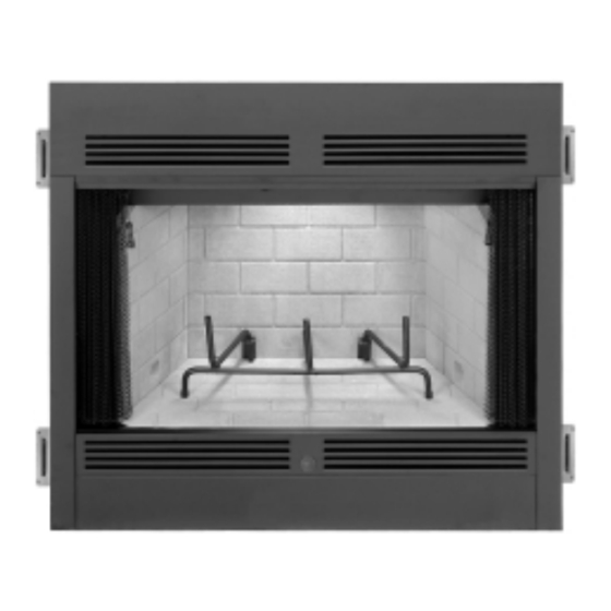
36" Wood-Burning Fireplaces
P/N 700040M Rev. B 10/2011
MODELS
BR-36
BRI-36
BR-36-2
This installation manual will enable you to obtain a safe, efficient and
dependable installation of your fireplace system. Please read and under-
stand these instructions before beginning your installation.
Do not alter or modify the fireplace or its components under any
circumstances. Any modification or alteration of the fireplace system,
including but not limited to the fireplace, chimney components and
accessories, may void the warranty, listings and approvals of this system
and could result in an unsafe and potentially dangerous installation.
IMPORTANT! TO ENSURE PROPER ALIGNMENT OF GLASS DOORS:
INSTALL THIS FIREPLACE IN A SQUARE AND PLUMB CONDITION,
USING SHIMS AS NECESSARY AT SIDES AND/OR BOTTOM.
RETAIN THESE INSTRUCTIONS
FOR FUTURE REFERENCE
US
BC-36
BCI-36
BC-36-2
OTL Report No. 116-F-43-2
Advertisement
Table of Contents

Related Manuals for Superior BC-36-2


Summary of Contents for Superior BC-36-2
-
Page 1: Installation Instructions
INSTALLATION INSTRUCTIONS STANDARD SERIES 36" Wood-Burning Fireplaces P/N 700040M Rev. B 10/2011 MODELS BR-36 BC-36 BRI-36 BCI-36 BR-36-2 BC-36-2 This installation manual will enable you to obtain a safe, efficient and dependable installation of your fireplace system. Please read and under- stand these instructions before beginning your installation. -
Page 2: Table Of Contents
2. Always check your local building codes. The The manufacturer is not responsible for any TABLE OF CONTENTS installation must comply with all local, regional, smoking or related problems that may result Safety Rules ........page 2 state and national codes and regulations. from the lack of adequate combustion air. -
Page 3: Precautions
PRECAUTIONS The "C" models are designed as heat circulating When complete these fireplace systems con- fireplaces and may be fitted with accessory sists of four basic “sub-systems”: fans. Note: These fireplace systems are not difficult 1. The Fireplace to install. However, in the interest of safety, it The BRI and BCI models are fully insulated for 2. -
Page 4: Assembly Outline
Chimney Height LOCATION OF FIREPLACE Insulate Joists Same As Ceiling The total height of your completed fireplace Carefully select the proper location for heat system from the surface the fireplace rests on circulation, aesthetics, chimney obstructions to the chimney top must not exceed 60' and and clearance to side wall(s). -
Page 5: Assembly Steps
ASSEMBLY STEPS 1. Estimate the total weight of the fireplace Top Spacer system including chimney and surround ma- terials such as brick, stone, etc., to be in- Note: The following steps represent the normal Maintain stalled. Shipping weights for the fireplace 1"... -
Page 6: Fireplace Specifications
FIREPLACE SPECIFICATIONS 1-1/2" 9-5/8" (38 mm) (244 mm) 7-1/2" (191 mm) 36" (914 mm) 37" (940 mm) 20-3/16" 1-1/2" Metal Safety Strips (513 mm) 27-7/8" (708 mm) 2" (51 mm) Figure 8 7-3/16" (183 mm) 40" (1016 mm) 43" Blocking (1092 mm) Front (BC Model Shown) Appliance Top Spacer... -
Page 7: Framing Specifications
FRAMING SPECIFICATIONS Framing Dimensions Back Wall of FOAK Combustion Chase/Enclosure Air Kit - Optional Including Finising 42-1/4" 1073 mm Materials if any 37-1/2" 953 mm 54-1/2" 1384 mm 28-3/4" 730 mm (See Note) 15-3/8" 391 mm Header 70" 1778 mm Rough Framing Face (Unfinished Shown) -
Page 8: Installing The Chimney System
Step 4. Fireplace should be fastened to side Note: If the fireplace is installed against an inside framing members using the nailing tabs at the wall, the Class 0 metallic air duct may be ex- tended into a ventilated attic space at least 18" top and bottom of the fireplace front face. -
Page 9: Offset Through Floor/Ceiling
CHIMNEY 30 OFFSET THROUGH FLOOR Step 4. Note: Chimney sections are con- Note: Assemble one component of chimney at structed with a unique locking tab design, a time (inner section first, then outer section OR CEILING which ensures an immediate, tight assembly last) before proceeding with the next complete between sections. - Page 10 Roof Ridge FTF8-S4 Stabilizer Figure 28 Note: Do not apply excessive pressure to any Figure 30 Figure 32 subsequent chimney sections following the stabilizer when installing. Ensure each subse- Step 8. Slide the FTF8 storm collar (ordered Step 10. Using a FTF8-CTD Round Termination: quent chimney section is securely attached by separately) over outer chimney, rest on flash- testing as noted in Step 4.
-
Page 11: Ten Foot Rule Summary
To determine the number of chimney sections Less Than 10' and chimney components required, follow these steps: 2' Min. 1. Determine total vertical height of the fireplace installation. This dimension is the distance from the surface the fireplace sets on to the point where smoke exits from the termination. -
Page 12: Vertical Elevation Chart
The offset and return elbows may be attached FTF8 VERTICAL ELEVATION CHART together, or a section or sections of chimney may be used between, but do not exceed 20' in Height Of Number Of FTF8 Height Of Number Of FTF8 total length between elbows. -
Page 13: Offset Elevation Chart
OFFSET ELEVATION CHART FTF8-ES30 Number of FTF8 Chimney Sections Return Offset Height Offset/Return FTF8-S4 Elbow (Inches) (Inches) Elbow Stabilizer 12" 18" 38" 48" Max. Stabilizer 10' Max. Offset Elbow Figure 36 Figure 37 NOTE: DIAGRAMS & ILLUSTRATIONS NOT TO SCALE. -
Page 14: Installing Offsets
Step 1. Determine the offset distance where chimney is to pass through the first ceiling- dimension “A.” To find this point on your ceil- Joints ing, first determine the center point for a verti- cal chimney following the instructions for ver- tical installation. -
Page 15: Combustion Air Kits
This provision is intended for connection to a POWER TO THE FIREPLACE WARNING: DO NOT REMOVE THE AC- The Optional Blower Kit decorative gas appliance incorporating an au- Operates on 115 volt 60 Hz TUATOR ARM LOCKING SCREW UNLESS 150 watts AC tomatic shut-off device and complying with the THE COMPLETE OUTSIDE AIR VENT SYS- Standard for Decorative Gas Appliances for... -
Page 16: Glass Doors
If you’re installing a gas line, connect it before Note: A 1"* air space must be preserved for all the fireplace is framed and enclosed in the combustible materials extending for any con- Finished 12" Wall tinuous length adjacent to the chimney. finished wall. - Page 17 Hearth Extension Dimensions 16" 35" 8" 51" Note: To convert inches to millimeters divide by 0.03937 Figure 47 Answer - The minimum required thickness of the Micore 160 is .417”, Methods of Determini ng Hearth Extension and Wall Shield therefore round up to nearest standard thickness available which is 1/2”. Equivalents - To determine the thickness required for the alternate material when either the “k”...
-
Page 18: Finish Requirements
The sum of all “R values” is: .70 + .10 +. 038 + .10 = .938 Wall Shield Required Where Less Than 12" This would NOT be an acceptable combination 24" of material for the hearth extension since the total calculated “R value” of the materials used 5 1/2"... -
Page 19: Installation Components
INSTALLATION COMPONENTS The following items are available for use in the (FBK-200 Models Only) installation of this appliance. Chimney Section 63L10 FTF8-12 63L13 FTF8-18 Forced Air Blower Kits 63L14 FTF8-36 -Single Speed 80L84 FBK-100 63L15 FTF8-48 Firestop Spacer (30 ) 63L30 F8FS30 -Variable Speed... - Page 20 INSTALLATION COMPONENTS Chase Termination Chase Termination (Square) 63L48 FTF8-CT1 (Square) 63L51 FTF8-CT2 Attic Shield Assembly 63L67 FTF8-FSAS** **Note: 2" clearance required for Canadian Chase Termination Installation - as applicable. Locking Band 63L60 (Round) 63L45 FTF8-CTDT NOTE: DIAGRAMS & ILLUSTRATIONS NOT TO SCALE. The manufacturer reserves the right to make changes at any time, without notice, in design, materials, specifications, and prices, and also to discontinue colors, styles, and products.