Table of Contents
Advertisement
Quick Links
Advertisement
Table of Contents

Related Manuals for Omron V500-R2 Series


Summary of Contents for Omron V500-R2 Series
- Page 1 V500-R2 Series User’s Manual Z334-E1-01A Cat. No.
- Page 2 Introduction Thank you for purchasing the OMRON V500-R2 series. This manual describes the functions, performance, and application methods of the V500-R2 series. This manual is intended for personnel with knowledge of electrical systems. Be sure to read and understand this manual thoroughly before using the product, and keep this manual in an easily accessible location for quick reference when required.
- Page 3 READ AND UNDERSTAND THIS DOCUMENT Introduction (Be sure to read this.) Product Overview Section 1 Wiring and Installation Section 2 Function Explanation Section 3 Setting Method Section 4 Example of System Configuration Section 5 Appendix Section 6 Bar Code Reader User’s Manual V500-R2 series...
- Page 4 PRODUCTS, WHETHER SUCH CLAIM IS BASED ON CONTRACT, WARRANTY, NEGLIGENCE, OR STRICT LIABILITY. In no event shall responsibility of OMRON for any act exceed the individual price of the product on which liability is asserted. IN NO EVENT SHALL OMRON BE RESPONSIBLE FOR WARRANTY, REPAIR, OR OTHER CLAIMS REGARDING THE PRODUCTS UNLESS OMRON’S ANALYSIS CONFIRMS THAT THE PRODUCTS...
- Page 5 Performance data given in this document is provided as a guide for the user in determining suitability and does not constitute a warranty. It may represent the result of OMRON’s test conditions, and the users must correlate it to actual application requirements. Actual performance is subject to the OMRON Warranty and Limitations of Liability.
-
Page 6: Introduction
Meanings of Signal Words In this manual, precautions are indicated using the following symbols and signal words to ensure safe use of the V500-R2 series. The precautions indicated by these symbols and signal words are important for safety and must be observed. -
Page 7: For The Safety Use Of Laser Products
1 mW max. Classification Labeling on Laser Use This Bar Code Reader has the following WARNING Label. This Bar Code Reader is compliant with IEC 60825 and the U.S. FDA (Food and Drug Administration) laser regulations. V500-R2 series User’s Manual... - Page 8 Class 3B laser products not exceeding five times the AEL of Class 2 in the wavelength range of 400 nm to 700 nm are to be treated as Class 3A laser products. V500-R2 series User’s Manual...
-
Page 9: Precautions For Safe Use
2. Power Supply and Wiring • To assure noise and insulation resistance, be sure to use S8VS-01505 (made by OMRON) as a driving power supply. • Do not connect a voltage or AC power supply that has a voltage exceeding the rating voltage (5 V+/-10%). -
Page 10: Regulations And Standards
• Dispose of the product as industrial waste. • If the product becomes extremely hot, or abnormal odors or smoke are emitted, stop using the product immediately, turn the power OFF, and consult with your OMRON representative. 5. Regulations and standards This product complies with the following standards. -
Page 11: Precautions For Correct Use
• droplets, water mist, oil or chemical agents. 2. Power supply, connection, and wiring • Be sure to use S8VS-01505 (made by OMRON) as a driving power supply. • Do not install the product in a location where a high-voltage device is installed. - Page 12 Introduction • V500-R2 series are precision instruments. Be careful not to give an impact or make them fall. • Do not hold the sensor only by the cable part when moving the sensor. A sensor body part will be damaged.
- Page 13 • Check for any dust or dirt on the reading window regularly. When it is dirty, wipe with a dry, soft and clean cloth. Do not use solutions such as thinner. • Handle with care, not to apply strong shock such as dropping. V500-R2 series User’s Manual...
-
Page 14: How To Use This Manual
Suffix 0D CR ETX, 0A LF, , or 0D0A CR+LF ON or The default settings are indicated with an asterisk. V500-R2 series User’s Manual V500-R2 series User’s Manual Procedure and additional explanations Information useful during the operation and reference pages are provided here with special marks to indicate the kind of information being provided. -
Page 15: Visual Aids
Introduction Visual Aids Indicates points that are important in using product functions or in application procedures. Indicates page numbers providing related information. Indicates helpful information when a problem occurs and explanations of technical terms. V500-R2 series User’s Manual... -
Page 16: Table Of Contents
Section 1 Product Overview Features Product Composition Part Names Rating/Performance Usage Flow Chart Section 2 Wiring and Installation Wiring Installation Section 3 Function Explanation Explanation of Reading System Operation Flow Chart Communication Data Format Test Reading Function V500-R2 series User’s Manual... - Page 17 Example of Connection with Programmable Controller (CS1) Example of Multi-drop Connection How to Use Command Link Unit V700-L12 Section 6 Appendix External Dimension Troubleshooting ASCII Code Table Explanation of Terms Corresponding Bar Code List Revision History V500-R2 series User’s Manual...
- Page 18 Introduction MEMO V500-R2 series User’s Manual...
-
Page 19: Product Overview
Section 1 Product Overview This section explains about features and rating/performance of this bar code reader. Features Product Composition Part Names Rating/Performance Usage Flow Chart V500-R2 series User’s Manual... -
Page 20: Features
Simple function setting You can either set the function by reading a menu sheet or by inputting a command on the upper equipment. You can select the setting method according to the condition. p.52 V500-R2 series User’s Manual... - Page 21 Connect communication link unit V700-L12 to collect read data from plural bar code readers (max. 31) for one set of upper equipment. p.102 Communication link unit V700-L12 Communication converter Upper K3SC Bar code reader equipment V500-R2 series Max. 31 sets V500-R2 series User’s Manual...
-
Page 22: Product Composition
Tip of the cable is a connector. Use an appropriate connecting cable according to the upper equipment. PC (PC/AT compatible) Cable for connecting with PC/AT compatible Bar code reader V509-W011D V500-R2 series p.98 Power supply (5 VDC) Recommended: S8VS-01505 Programmable controller Programmable controller made by OMRON p.99 Connecting cable V509-W011 V500-R2 series User’s Manual... -
Page 23: Part Names
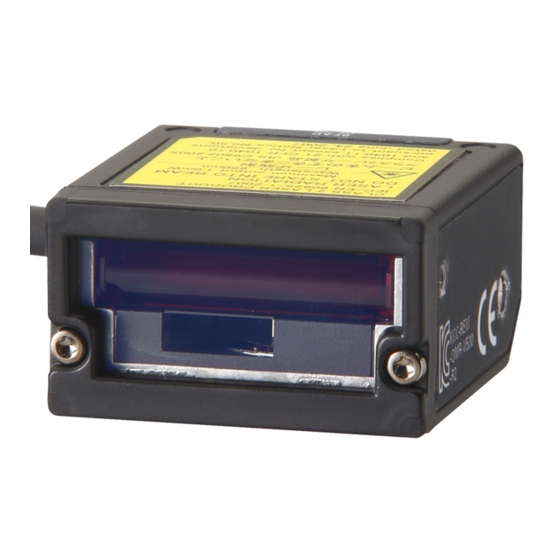
Section 1 Product Overview Part Names Front side Main cable Laser alarm label Reading window Laser beam radiates from here Back side READ OK LED Illuminates when read correctly. SCAN button Press it once to read once. V500-R2 series User’s Manual... -
Page 24: Rating/Performance
Notifies a successful reading with a buzzer sound (Muting available) Power supply Power voltage 4.5 to 5.5 VDC specification Consumption current During operation: 500 mA or less; during standby: 150 mA or less Inrush current 2.0 A MAX V500-R2 series User’s Manual... - Page 25 * Unless otherwise specified, use a JAN x1 , MRD 63% or higher (PCS = 0.9 or higher) barcode with a pitch angle γ α = 0°, a skew angle β = 15°, a tilt angle = 0°, and a curvature R = ∞. V500-R2 series User’s Manual...
- Page 26 Reading distance Narrow bar width (*1) 0.15 mm 70 to 140 mm 0.25 mm 60 to 200 mm 0.5 mm 60 to 270 mm 1.0 mm 70 to 330 mm Distance from the end of the case. V500-R2 series User’s Manual...
-
Page 27: Pitch Angle
Resolution = 0.25 mm, CODE39 (9 digits), PCS = 0.9 • Reading distance: 110 mm from the case end • Installation condition: Pitch angle α = 0°, tilt angle γ = 0°, curvature R = ∞ −β +β V500-R2 series User’s Manual... -
Page 28: Tilt Angle
• Bar code: Resolution = 0.26 mm, EAN, PCS = 0.9 • Reading distance: 110 mm from the case end • Installation condition: Pitch angle α = 0°, skew angle β = 15°, tilt angle γ = 0° V500-R2 series User’s Manual... -
Page 29: Usage Flow Chart
Check that the bar code in subject can be read. p.48 Test Reading Function Investigate the reading timing and moving speed. p.37 Operation Flow Chart Set the reading condition corresponding to the purpose. p.56 Menu Sheet/Command List V500-R2 series User’s Manual... - Page 30 Setting for label registration In case of trouble: A bar code cannot be read correctly. I don't know the communication specification. p.129 Troubleshooting p.45 Communication Data Format I can't understand the operation flow. p.37 Operation Flow Chart V500-R2 series User’s Manual...
-
Page 31: Wiring And Installation
Section 2 Wiring and Installation This section explains about the wiring method and installation method of the bar code reader. Wiring Installation V500-R2 series User’s Manual... -
Page 32: Wiring
• Wiring should avoid approaching to a high-power heavy electric current wire. • Turn off the power switch before connecting or disconnecting a connector. • To assure noise and insulation resistance, be sure to use S8VS-01505 (made by OMRON) as a driving power supply. -
Page 33: Power Supply
You can select the output logic of READ OK and READ NG signal. Power supply Recommended parts for the power supply Manufacturer Model OMRON Corporation S8VS-01505 Input/output circuit Input circuit for the external trigger signal (V500-R2 series) External trigger signal TRIG Internal circuit Von/off Minimum Maximum... - Page 34 Leak current at OFF 0.5 mA or less Residual voltage at ON 1 V or less Cable specification • Shape: Straight cable φ3.8 mm • Diameter: 1500 ± 50 mm • Length: • Number of core: 9 V500-R2 series User’s Manual...
-
Page 35: Installation
To avoid regular reflection of laser, incline approx. 15° against the bar code subject to read when installing the bar code reader. Use this mounting bracket as the mounting surface of an associated mounting bracket is inclined 15°. V500-R2 series to 60 °... - Page 36 Section 2 Wiring and Installation MEMO V500-R2 series User’s Manual...
-
Page 37: Function Explanation
Section 3 Function Explanation This section explains about representative functions of the bar code reader. Explanation of Reading System Operation Flow Chart Communication Data Format Test Reading Function V500-R2 series User’s Manual... -
Page 38: Explanation Of Reading System
Outputs data continuously even for the same bar code. Effective duration of reading When the trigger input method is external trigger signal effective duration designation system or RS-232C command, effective duration setting is required beforehand. Effective duration setting method p.75 V500-R2 series User’s Manual... -
Page 39: Operation Flow Chart
Process when reading succeeded When the trigger by a command is used, ignore this clause. In case of trigger controlled system (reads while the trigger is ON), consider that the reading effective duration is set to 0. V500-R2 series User’s Manual... - Page 40 Process when reading failed When the trigger by a command is used, ignore this clause. In case of trigger controlled system (reads while the trigger is ON), consider that the reading effective duration is set to 0. V500-R2 series User’s Manual...
- Page 41 Process when reading failed When the trigger by a command is used, ignore this clause. In case of trigger controlled system (reads while the trigger is ON), consider that the reading effective duration is set to 0. V500-R2 series User’s Manual...
- Page 42 Nonprocedural system (no protocol system) The bar code reader transmits the data to the upper equipment and ends. Bar code reader V500-R2 series Data Upper equipment ACK/NAK system This bar code reader waits for the upper equipment response after transmitting the data.
- Page 43 (Data length) + (1: In case when parity exists) + (Number of stop bit) (Number of digit of transmission data + Communication Number of header characters + time (ms) = (Communication speed) Number of footer characters) x 10 V500-R2 series User’s Manual...
- Page 44 (Data length) + (1: In case when parity exists) + (Number of digit of transmission data + Communication (Number of stop bit) Number of header characters + time (ms) = (Communication speed) Number of footer characters) x 10 V500-R2 series User’s Manual...
- Page 45 When the timing is too slow... The bar code is already passed and cannot read. Photoelectronic sensor Checking the tack timing In case when bar codes come continuously, calculate how close the bar codes may come, considering above two points. V500-R2 series User’s Manual...
- Page 46 Whole height of a bar code is scanned. In case of tall size label, this direction is stable. A part of the height of a bar code is scanned. In case of short size label, this direction is stable. V500-R2 series User’s Manual...
-
Page 47: Communication Data Format
This section explains about communication data format of the bar code reader and the upper equipment. Bar code reader Upper equipment V500-R2 series Reading data output Input command Reading trigger input by RS-232C command Reading trigger command format is as shown below. - Page 48 [STX]?[ETX], [STX]>[ETX] is transferred When it is judged as no bar code >: In cases other than above ?[CR], >[CR] are transferred [CAN] [CR] are transferred – [STX] [CAN] [ETX] are transferred – Setting method p.73 V500-R2 series User’s Manual...
- Page 49 Add a control character "C1" (ASCII code 5D, 43, 31) which indicates GS1-128, at the head of the transfer data. Also, FNC1 character, as a separating character, is replaced to GS (ASCII code 1DH) character and transferred. Setting method p.64 V500-R2 series User’s Manual...
-
Page 50: Test Reading Function
Of those, correct reading data (*) detected rate = Reading rate Correct reading data (*) Data, which detected most during measurement mode, is “correct reading data”. Communication data format [ 3 A 500d SPACE 93.5% ABCDE V500-R2 series User’s Manual... - Page 51 Reading is not stable. Check if there is no dirt or lack on the bar code. 0~25 % Check if the installation location and angle of the bar code reader is appropriate once more. LED indication : Lights out : Blink : Illuminate V500-R2 series User’s Manual...
- Page 52 Section 3 Function Explanation MEMO V500-R2 series User’s Manual...
-
Page 53: Setting Method
Section 4 Setting Method This section explains about setting methods using a menu sheet and entering command from the upper equipment. How to Use Menu Sheet/Command Menu Sheet/Command List V500-R2 series User’s Manual... -
Page 54: How To Use Menu Sheet/Command
Read the item on the menu sheet you want to change setting. Menu Sheet/Command List p.56 To finish setting, read "ZZ" on the menu sheet for setting start/end, again. Buzzer sound stops and returns to normal mode. _ZZ_ V500-R2 series User’s Manual... - Page 55 You can create a menu sheet using bar code creation software available in the market, as shown below. E.g.: When creating a menu sheet "A3" Create "* A3 *" and cut the parts of "*" with scissors to create the menu sheet "A3". Cutting off section Cutting off section V500-R2 series User’s Manual...
- Page 56 Section 4 Setting Method Input command from the upper equipment Bar code reader Upper equipment V500-R2 series Transmit command character strings. Transmit the command character strings of the function you want to set. Command (In case of one character, m1 only) Menu Sheet/Command List p.56...
- Page 57 Transmit 41 "A" in hexadecimal number. Transmit 42 "B" in hexadecimal number. Transmit CR code. "00H" (zero) cannot be designated as header or footer. It is regarded as end character. Characters until just before 00H are valid. V500-R2 series User’s Manual...
-
Page 58: Menu Sheet/Command List
Setting for READ OK signal output p.77 Setting for label registration p.79 Setting for communication conditions p.80 Setting for the communication protocol p.82 Setting for the header and footer p.83 Number of digit output p.84 Direct code designation p.85 V500-R2 series User’s Manual... -
Page 59: Start/End Setting Using Menu Sheets
Setting for external trigger signal Select positive logic or negative logic of the external trigger signal. Menu sheet Command External trigger signal, positive logic (H active) _YA_ External trigger signal, negative logic (L active) (factory default setting) _YB_ V500-R2 series User’s Manual... -
Page 60: Return To The Factory Default Setting
Not specified digits Reading valid time 2 seconds Plural reading reset 6 frames time READ OK LED illumination time: 200 ms Buzzer Enable the buzzer Single-tone buzzer Buzzer sound duration: 50 ms Buzzer sound volume: Max V500-R2 series User’s Manual... - Page 61 Communication speed 9600 bps conditions Data length 8 bits Parity None Stop bit 1 bit Header None Footer Number of digit output None RS/CS control None (no protocol system) CS waiting time Not limited ACK/NAK waiting time Not limited V500-R2 series User’s Manual...
-
Page 62: Collective Setting
Buzzer sound duration after decoding is 200 ms. Buzzer sound volume Max. Buzzer frequency 3 kHz, 2 kHz External trigger signal Negative logic (L active) READ OK/NG signal output Output READ OK/NG signal output system Trigger synchronous system, positive logic (H active) V500-R2 series User’s Manual... - Page 63 Buzzer sound duration after decoding is 200 ms. Buzzer sound volume Max. Buzzer frequency 3 kHz, 2 kHz External trigger signal Negative logic (L active) READ OK/NG signal output Output READ OK/NG signal output system Trigger synchronous system, positive logic (H active) V500-R2 series User’s Manual...
-
Page 64: Setting Of Reading Permission And Prohibition
Permission for UPC add-on 5-digit codes _R3_ Reading permission for JAN/EAN codes _R4_ Permission for EAN add-on 2-digit codes _R5_ Permission for EAN add-on 5-digit codes _R6_ Reading permission for CODE39 codes _B2_ Reading permission for Cadabar(NW-7) codes _B3_ V500-R2 series User’s Manual... - Page 65 Reading permission for ITF codes _R8_ Reading permission for CODE128 codes _B6_ Reading permission for CODE93 codes _B5_ Reading permission for GS1 DataBar(RSS-14) codes _JX_ Reading permission for GS1 DataBar(RSS-Limited) codes _JY_ Reading permission for GS1 DataBar(RSS-Expanded) codes _DR_ V500-R2 series User’s Manual...
-
Page 66: Detail Setting For Reading Code
Transfer C/D without an 0 in the beginning (Factory default setting) _E7_ Not transfer C/D without an 0 in the beginning _E9_ Transfer C/D with 0 in the beginning _E6_ Not transfer C/D with 0 in the beginning _E8_ V500-R2 series User’s Manual... -
Page 67: V500-R2 Series
Transfer C/D (Factory default setting) _6I_ Not transfer C/D _6H_ CODE39 Menu sheet Command Not calculate C/D (Factory default setting) _C1_ Calculate C/D _C0_ Transfer C/D (Factory default setting) _D9_ Not transfer C/D _D8_ Transfer ST/SP _D0_ V500-R2 series User’s Manual... - Page 68 Not calculate C/D (Factory default setting) _H7_ Calculate C/D _H6_ Transfer C/D (Factory default setting) _H8_ Not transfer C/D _H9_ Not transfer ST/SP (Factory default setting) _F0_ ST/SP: ABCD/ABCD _F3_ ST/SP: abcd/abcd _F4_ ST/SP: ABCD/TN*E _F1_ ST/SP: abcd/tn*e _F2_ V500-R2 series User’s Manual...
- Page 69 Not calculate C/D (Factory default setting) _G0_ Calculate C/D _G1_ Transfer C/D (Factory default setting) _E0_ Not transfer C/D _E1_ Data character of at least 1 digit _GE_ Data character of at least 3 digits _GF_ V500-R2 series User’s Manual...
- Page 70 Data character of at least 5 digits _GI_ GS1-128(EAN-128) Menu sheet Command Disable GS1 conversion (Factory default setting) [X/0 _X/0_ Enable GS1 conversion [X/4 _X/4_ GS1-Databar(RSS) Menu sheet Menu sheet Command Not transfer C/D _DM_ Transfer C/D _DL_ V500-R2 series User’s Manual...
-
Page 71: Setting For The Number Of Times Of Reading Coincidence
Reading twice and verification once (Factory default setting) _X1_ Reading three times and verification twice _X2_ Reading four times and verification three times _X3_ Reading five times and verification four times _BS_ Reading six times and verification five times _BT_ V500-R2 series User’s Manual... -
Page 72: Setting For Reading Operation
The time during which the reading continues after a trigger is input is set. When it is set to 0 sec., reading is controlled by the external trigger and the trigger is effective while the external trigger is ON. Menu sheet Command 0 seconds (controlled by the external trigger) _Y0_ 1 second _Y1_ V500-R2 series User’s Manual... - Page 73 Section 4 Setting Method Menu sheet Command 2 seconds (Factory default setting) _Y2_ 3 seconds _Y3_ 4 seconds _Y4_ 5 seconds _Y5_ 6 seconds _Y6_ 7 seconds _Y7_ 8 seconds _Y8_ 9 seconds _Y9_ Infinity _YM_ V500-R2 series User’s Manual...
-
Page 74: Setting For Plural Reading Reset Time
(Example) Frame Time (ms) 100 200 300 400 500 Menu sheet Command 1 frame _AH_ 2 frames _AI_ 3 frames _AJ_ 4 frames _AK_ 5 frames _AL_ 6 frames (Factory default setting) _AM_ Infinity _AG_ V500-R2 series User’s Manual... -
Page 75: Setting For Failed Reading
Error - No label (TH) Error - Decoding failure (TI) N (0N) N (0N) L (0L) D (0D) <CR> (1M) <CR> (1M) Setting end (ZZ/Z2) Setting end (ZZ/Z2) Menu sheet Command Error message - No label _TH_ V500-R2 series User’s Manual... -
Page 76: Setting For The Number Of Reading Digits
Read the second code of the necessary length Setting end (ZZ) Menu sheet Command Fixed number of digits OFF for all codes (Factory default setting) _H0_ Fixed number of digits ON for all codes None _H1_ V500-R2 series User’s Manual... -
Page 77: Setting For The Read Ok Led
The buzzer is enabled or disabled or its type and sound duration and volume are set. The buzzer sounds when reading succeeds. Menu sheet Command Disable the buzzer _W0_ Enable the buzzer (Factory default setting) _W8_ Single-tone buzzer (Factory default setting) _W1_ V500-R2 series User’s Manual... - Page 78 _W4_ Buzzer sound duration: 200 ms _W5_ Buzzer sound duration: 400 ms _W6_ Buzzer sound volume: Max (Factory default setting) _T0_ Buzzer sound volume: High _T1_ Buzzer sound volume: Medium _T2_ Buzzer sound volume: Low _T3_ V500-R2 series User’s Manual...
-
Page 79: Setting For Read Ok Signal Output
[X*D _X*D_ One-shot system (positive logic, H active) [X*E _X*E_ One-shot system (negative logic, L active) [X*F _X*F_ One-shot duration: 10 ms [X*G _X*G_ One-shot duration: 20 ms [X*H _X*H_ One-shot duration: 30 ms [X*I _X*I_ V500-R2 series User’s Manual... - Page 80 One-shot duration: 50 ms [X*K _X*K_ One-shot duration: 60 ms [X*L _X*L_ One-shot duration: 70 ms [X*M _X*M_ One-shot duration: 80 ms [X*N _X*N_ One-shot duration: 90 ms [X*O _X*O_ One-shot duration: 100 ms [X*P _X*P_ V500-R2 series User’s Manual...
-
Page 81: Setting For Label Registration
Read the second code you want to register Read the fifth code you want to register Setting end (ZZ) Menu sheet Command Register labels _+9_ To cancel a label registration, end the setting without reading a label in label registration processing. V500-R2 series User’s Manual... -
Page 82: Setting For Communication Conditions
Communication speed: 2400 bps _K4_ Communication speed: 4800 bps _K5_ Communication speed: 9600 bps (Factory default setting) _K6_ Communication speed: 19200 bps _K7_ Communication speed: 38400 bps _K8_ Communication speed: 57600 bps _K9_ Communication speed: 115200 bps _SZ_ V500-R2 series User’s Manual... - Page 83 _L0_ Data length: 8 bits (Factory default setting) _L1_ Parity: None (Factory default setting) _L2_ Parity: Even number _L3_ Parity: Odd number _L4_ Stop bit: 1 bit (Factory default setting) _L5_ Stop bit: 2 bits _L6_ V500-R2 series User’s Manual...
-
Page 84: Setting For The Communication Protocol
Communication protocol: With RS/CS control (Ready/Busy system) _P1_ Communication protocol: ACK/NAK system _P3_ CS waiting time: Not limited (Factory default setting) _I0_ CS waiting time: 100 ms _I1_ CS waiting time: 200 ms _I2_ CS waiting time: 400 ms _I3_ V500-R2 series User’s Manual... -
Page 85: Setting For The Header And Footer
Menu sheet Command Set the headers collectively (Applied to all codes) _RY_ Clear the header (Applied to all codes) _MG_ Set the footers collectively (Applied to all codes) _RZ_ Clear the footer (Applied to all codes) _PR_ V500-R2 series User’s Manual... -
Page 86: Number Of Digit Output
"05" when the data of the barcode of the scanned code is "ABCDE". • When the number of digits output is set to [ZZRY$6ZZ] (barcode 6 digits), the number of digits is "000005" when the data of the barcode of the scanned code is "ABCDE". V500-R2 series User’s Manual... -
Page 87: Direct Code Designation
Section 4 Setting Method Direct code designation Used to set character strings and values directly when designating the header or footer. Menu sheet Command <SPACE> _5A_ _5B_ " _5C_ _5D_ _5E_ _5F_ & _5G_ _5H_ _5I_ _5J_ V500-R2 series User’s Manual... - Page 88 Section 4 Setting Method Menu sheet Command _5K_ _5L_ _5M_ _5N_ _5O_ _5P_ _6A_ _6B_ < _6C_ _6D_ > _6E_ V500-R2 series User’s Manual...
- Page 89 Section 4 Setting Method Menu sheet Command _6F_ _6G_ _7A_ _7B_ _7C_ _7D_ _7E_ _7F_ _9T_ _9U_ _9V_ V500-R2 series User’s Manual...
- Page 90 Section 4 Setting Method Menu sheet Command _9W_ _Q0_ _Q1_ _Q2_ _Q3_ _Q4_ _Q5_ _Q6_ _Q7_ _Q8_ _Q9_ V500-R2 series User’s Manual...
- Page 91 Section 4 Setting Method Menu sheet Command _0A_ _0B_ _0C_ _0D_ _0E_ _0F_ _0G_ _0H_ _0I_ _0J_ _0K_ V500-R2 series User’s Manual...
- Page 92 Section 4 Setting Method Menu sheet Command _0L_ _0M_ _0N_ _0O_ _0P_ _0Q_ _0R_ _0S_ _0T_ _0U_ _0V_ V500-R2 series User’s Manual...
- Page 93 Section 4 Setting Method Menu sheet Command _0W_ _0X_ _0Y_ _0Z_ _$A_ _$B_ _$C_ _$D_ _$E_ _$F_ _$G_ V500-R2 series User’s Manual...
- Page 94 Section 4 Setting Method Menu sheet Command _$H_ _$I_ _$J_ _$K_ _$L_ _$M_ _$N_ _$O_ _$P_ _$Q_ _$R_ V500-R2 series User’s Manual...
- Page 95 Section 4 Setting Method Menu sheet Command _$S_ _$T_ _$U_ _$V_ _$W_ _$X_ _$Y_ _$Z_ (NULL) _9G_ (SOH) _1A_ (STX) _1B_ V500-R2 series User’s Manual...
- Page 96 Section 4 Setting Method Menu sheet Command (ETX) _1C_ (EOT) _1D_ (ENQ) _1E_ (ACK) _1F_ (BEL) _1G_ (BS) _1H_ (HT) _1I_ (LF) _1J_ (VT) _1K_ (FF) _1L_ (CR) _1M_ V500-R2 series User’s Manual...
- Page 97 Section 4 Setting Method Menu sheet Command (SO) _1N_ (SI) _1O_ (DLE) _1P_ (DC1) _1Q_ (DC2) _1R_ (DC3) _1S_ (DC4) _1T_ (NAK) _1U_ (SYN) _1V_ (ETB) _1W_ (CAN) _1X_ V500-R2 series User’s Manual...
- Page 98 Section 4 Setting Method Menu sheet Command (EM) _1Y_ (SUB) _1Z_ (ESC) _9A_ (FS) _9B_ (GS) _9C_ (RS) _9D_ (US) _9E_ DELL _9F_ V500-R2 series User’s Manual...
-
Page 99: Example Of System Configuration
Example of System Configuration This section explains about connection method with upper equipment. Example of Connection with a PC Example of Connection with Programmable Controller (CS1) Example of Multi-drop Connection How to Use Command Link Unit V700-L12 V500-R2 series User’s Manual... -
Page 100: Example Of Connection With A Pc
Section 5 Example of System Configuration Example of Connection with a PC Example of connection with PC/AT compatible PC is explained. Bar code reader V500-R2 series PC/AT compatible PC Special cable V509-W011D AC 100 V Power supply for bar code... -
Page 101: Example Of Connection With Programmable Controller (Cs1)
Section 5 Example of System Configuration Example of Connection with Programmable Controller (CS1) Connection with programmable controller CS1 (Made by OMRON) is explained. Input unit CPU unit Programming C200H-ID212 Bar code reader Power supply unit CS1H-CPU64-V1 console V500-R2 series C200HW-PA204S... - Page 102 For detail setting method, refer to the operation manual of your programmable controller. Setting item Setting content Dip switch of CPU unit PC system setting 160[8300] 161[0000] 164[000D] 165[0100] DM setting Set [1B5A] to DM00100. (Memorize "Z" of ASCII code) V500-R2 series User’s Manual...
- Page 103 DM00200 and displays the content on the #0000 programming console. A393 MSG (46) &0 DM0200 For the program command, refer to the operation manual of your programming console. (Items related to communication method by RS-232C nonprocedural system.) V500-R2 series User’s Manual...
-
Page 104: Example Of Multi-Drop Connection
Communication converter K3SC RS-232C RS-485 Communication link unit RS-485 RS-485 Machine Machine Machine V700-L12 No. 01 No. 03 No. 02 Power supply 24 VDC S8VS-03024 External trigger Special cable Input terminal V509-W019 Bar code reader V500-R2 series V500-R2 series User’s Manual... - Page 105 ON (*) SW10 is ON In case of connection example shown here, termination resistors of the machine No. 3 and the upper equipment (interface converter) are turned ON. Specification and wiring of the link unit p.103 V500-R2 series User’s Manual...
- Page 106 Stores data Polling Data export of Machine Link unit No. 1 Returns data Polling Data export of Machine Link unit No. 2 Returns data Polling Data export of Machine Link unit No. 3 Returns data Data export V500-R2 series User’s Manual...
-
Page 107: Communication Format
E.g.: When the read data is not accumulated (Machine No.) (Check code) Code indicating that there is no data When the bar code reader setting is changed from the upper equipment (Machine No.) ESC (m1) (m2) (Check code) Command character string V500-R2 series User’s Manual... -
Page 108: How To Use Command Link Unit V700-L12
Illuminate in the event of a failure during data communication with upper equipment or a bar code reader. GR (frame ground) terminal is in the multi-connection port. D type grounding (former type 3 grounding) should be performed. V500-R2 series User’s Manual... -
Page 109: General Specification
It does not transmit the received reply to the upper equipment. • When inputting data from the ID port, it transmits to the upper equipment immediately. RS-485 termination resistance OFF (invalid) ON (valid) DIP-SW is used for setting each function. V500-R2 series User’s Manual... - Page 110 6.0 mm or less Connect 24 V power supply device. Recommended device Manufacturer Model OMRON Corporation S8VS-03024 Confirmation should be fully made if there is no mistake after wiring. Faulty wiring may be the cause of failure. V500-R2 series User’s Manual...
- Page 111 • Through procedure (immediate transmission system): ON RS-485 termination OFF (invalid) Set whether to make RS-485 termination resistance valid. Turn resistance on the link unit on both sides of transmission path. (When only one set is connected, turn it ON.) V500-R2 series User’s Manual...
- Page 112 Cable length Max. 15 m Communication system In compliance with RS-232C Synchronous system Asynchronous system Communication control system One-to-N procedure dedicated to OMRON Communication speed 4800/9600/19200/38400 bps (Set with DIP-SW) Character format (fixed) Start bit Data bit Parity bit Stop bit...
- Page 113 D-SUB 9 pin Signal Signal Pin No. Pin No. name name Ground the shield wire on either PC/AT compatible PC side or link unit side. When CS function is used on PC side, a return line is required. V500-R2 series User’s Manual...
- Page 114 Cable length Total length: Max. 1 km Communication system In compliance with RS-485 Synchronous system Asynchronous system Communication control system One-to-N procedure dedicated to OMRON Communication speed 4800/9600/19200/38400 bps (Set with DIP-SW) Character format (fixed) Start bit Data bit Parity bit...
- Page 115 Fixing screw Uncoupling the connector Loosen two fixing screws completely and pull off the connector straight back holding the protrusion. When it is not pulled off easily, hold the link unit body and pull it again. V500-R2 series User’s Manual...
- Page 116 5 V ±5 % supply Communication Communication In compliance with RS-232C part system Synchronous Asynchronous system system Communication One-to-one procedure dedicated to OMRON control system Communication 9600 bps speed (fixed) Character format Total Start bit Data bit Parity bit Stop bit...
- Page 117 Example of System Configuration Command specification Command to control the link unit (in case of one-to-N procedure dedicated to OMRON) is explained in this section. Transmit so that distance between each character of the command is less than 200 ms. When the distance is 200 ms or more, it is recognized as separation of commands.
- Page 118 In case of "Through procedure (normal output procedure)", no response is output even if command is input. Resend request (R) The response sent before is transmitted again. Input command (Machine No.) (Check code) Response (Machine No.) Communication data with the bar code (same as immediately before) (Check code) V500-R2 series User’s Manual...
- Page 119 Communication frame with the bar code is as shown below. Communication data with the bar code reader Control code indicating frame start Control code indicating frame end However, it returns to default ([CR] mode) when the power is turned on or off. V500-R2 series User’s Manual...
- Page 120 Set to machine No. 3 DIP-SW 1 to 5: Set to machine No. 1 With termination DIP-SW10: No termination No termination No termination resistance (ON) resistance (OFF) resistance (OFF) resistance (OFF) Total length: Max. 1 km V500-R2 series User’s Manual...
- Page 121 (OFF) resistance (OFF) resistance (ON) resistance (OFF) Total length: Max. 1 km The upper equipment should be in data reception condition within 15 ms after data transmission. This control should be performed for normal operation. V500-R2 series User’s Manual...
- Page 122 • RS signal control of the upper equipment (Turns OFF before ending command transmission) (*2) • RS signal control of the upper equipment (RS signal is always ON) (*2) • 24 VDC power source line check Upper connection port p.110 V500-R2 series User’s Manual...
- Page 123 Bar code reader • Cable wiring of the bar code reader (effect of circumference communication malfunction noise) Bar code reader malfunction • Connection of the interface connector to the bar code reader • Bar code reader cable disconnection V500-R2 series User’s Manual...
- Page 124 Section 5 Example of System Configuration MEMO V500-R2 series User’s Manual...
-
Page 125: Appendix
Section 6 Appendix External Dimension Troubleshooting ASCII Code Table Explanation of Terms Corresponding Bar Code List V500-R2 series User’s Manual... -
Page 126: External Dimension
External Dimension Bar code reader V500-R2CF (Unit: mm) 6.25 M3 Depth 3 Light axis M3 Depth 3 Connector Vinyl insulated round cord φ3.8 10-core Black Standard length 1.5 m 2-M5 Mounting hole dimensions Light axis 7.19 4.45 V500-R2 series User’s Manual... - Page 127 Section 6 Appendix Cable for programmable controller connection made by OMRON V509-W011 (Unit: mm) Vinyl insulated round cord φ5.1 Vinyl insulated round cord φ3.8, 3-core (conductor section area: D-sub 9 pin 0.2 mm , diameter of insulation body: φ1.0 mm)
- Page 128 Pink (external trigger) Brown (+5V) Blue (0V) Upper equipment side D-sub 9 pin Bar code reader side DIN 8 pin Signal name Shield cable No. Signal name TRIG Connector Shield wire Cover Shielded (External trigger) (+5V) (0V) V500-R2 series User’s Manual...
- Page 129 φ1.0 mm) Pink (external trigger) Blue (0V) Upper equipment side D-sub 9 pin Signal name Bar code reader side DIN 8 pin Shield cable No. Signal name TRIG Connector Shield wire Cover Shielded (External trigger) (0V) V500-R2 series User’s Manual...
- Page 130 Section 6 Appendix Communication link unit V700-L12 (Unit: mm) 2-φ4.5 Dimension of mounting hole process 2-M4 or φ4.2 V500-R2 series User’s Manual...
-
Page 131: Troubleshooting
1. Check the operation of the upper unit side and the of the upper equipment operation manual. side correct? Change the bar code reader. (Or send it back to the manufacturer.) Troubleshooting when communication link unit is used p.120 V500-R2 series User’s Manual... -
Page 132: Ascii Code Table
Section 6 Appendix ASCII Code Table Data Data Data Data Character (Hexadecim Character (Hexadecim Character (Hexadecim Character (Hexadecim al number) al number) al number) al number) " & – < ¥(\) > V500-R2 series User’s Manual... -
Page 133: Explanation Of Terms
"Parity check" is a data check system which adds 1 bit to data and to have the total bit of "1" either in even number or odd number. The added 1 bit at this time is called "parity bit". V500-R2 series User’s Manual... - Page 134 Even digit 4 = 10 10 x 3 = 30 Odd digit = 13 30 + 13 = 43 (1st digit is 3) 10 - 3 = 7•••Check digit Therefore, data with check character is "49012347". V500-R2 series User’s Manual...
- Page 135 Numerical conversion 12 + 24 + 13 + 14 + 38 + 3 + 9 = 113 113 / 43 = 2 Remainder 27 (Character of 27 is R) R ... Check digit Therefore, data with check character is "CODE39R". V500-R2 series User’s Manual...
- Page 136 Numerical conversion 16 + 3 + 7 + 8 + 5 + 9 +17 = 65 65 / 16 = 4 Remainder 1 (Character of 1 is +) + ... Check digit Therefore, data with check character is "A37859B+". V500-R2 series User’s Manual...
- Page 137 When "All reading allowed including EAN (G5)" is set, CODE128 other than this combination can be read. Start pattern of GS1-128 is converted to "C1" (5Dh43h31h in ASCII code) and output. "FNC1" (separator) indicating data separation is converted to "GS" and output. V500-R2 series User’s Manual...
-
Page 138: Corresponding Bar Code List
Section 6 Appendix Corresponding Bar Code List Bar code EAN, UPC CODE39 Industrial2of5(STF) Codabar(NW-7) CODE93 CODE128 V500-R2 series User’s Manual... - Page 139 Section 6 Appendix GS1 DataBar (RSS) GS1 DataBar Omni-directional GS1 DataBar Truncated GS1 DataBar Stacked GS1 DataBar Limited GS1 DataBar Expanded V500-R2 series User’s Manual...
- Page 140 READ OK Luster scan Effective duration Effective duration designation Machine No. system Margin End setting Menu sheet External dimension figure Modulus check External trigger signal Mounting bracket Moving direction Multi-connection port Multi-drop Communication format Flow chart V500-R2 series User's Manual...
- Page 141 READ OK signal Reading angle Reading coincidence Reading failed Reading operation Reading permission/prohibition Reading range Reading rate measurement mode 48 Reading system Reading time Reading trigger Reading valid time Reading window Ready/Busy system RS/CS control RS-232C command V500-R2 series User's Manual...
-
Page 142: Revision History
A manual revision code appears as a suffix to the catalog number at the bottom of the front and back covers. Z334-E1-01A Cat. No. Revision code Reprint code Date Revised contents January 2013 Original production March 2013 Minor corrections V500-R2 series User’s Manual... - Page 144 IL 60173-5302 U.S.A. Carl-Benz-Str. 4, D-71154 Nufringen, Germany Tel: (1) 847-843-7900/Fax: (1) 847-843-7787 Tel: (49) 7032-811-0/Fax: (49) 7032-811-199 © OMRON Corporation 2012 All Rights Reserved. OMRON (CHINA) CO., LTD. OMRON ASIA PACIFIC PTE. LTD. In the interest of product improvement, Room 2211, Bank of China Tower, No.