Table of Contents
Advertisement
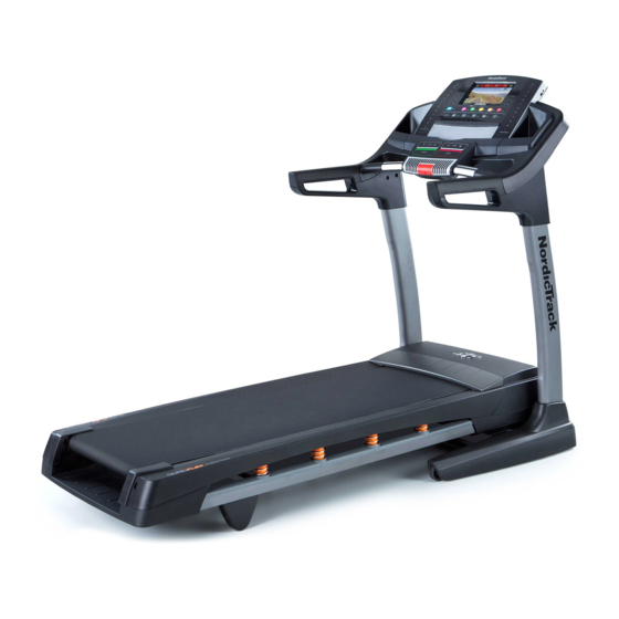
Model No. NETL18711.0
Serial No.
Write the serial number in the space
above for reference.
Serial Number
Decal
QUESTIONS?
If you have questions, or if there are
missing parts, please contact us:
UNITED KINGDOM
Call: 08457 089 009
From Ireland: 053 92 36102
Website: www.iconsupport.eu
E-mail: csuk@iconeurope.com
Write:
ICON Health & Fitness, Ltd.
c/o HI Group PLC
Express Way
CASTLEFORD
WF10 5QJ
UNITED KINGDOM
AUSTRALIA
Call: 1800 993 770
E-mail: australiacc@iconfitness.com
Write:
ICON Health & Fitness
PO Box 635
WINSTON HILLS NSW 2153
AUSTRALIA
CAUTION
Read all precautions and instruc-
tions in this manual before using
this equipment. Save this manual
for future reference.
USER'S MANUAL
www.iconeurope.com
Advertisement
Table of Contents

Related Manuals for NordicTrack T23.0


Summary of Contents for NordicTrack T23.0
- Page 1 Model No. NETL18711.0 Serial No. USER’S MANUAL Write the serial number in the space above for reference. Serial Number Decal QUESTIONS? If you have questions, or if there are missing parts, please contact us: UNITED KINGDOM Call: 08457 089 009 From Ireland: 053 92 36102 Website: www.iconsupport.eu E-mail: csuk@iconeurope.com...
-
Page 2: Table Of Contents
Apply the decal in the location shown. Note: The decals may not be shown at actual size. NORDICTRACK is a registered trademark of ICON IP, Inc. -
Page 3: Important Precautions
IMPORTANT PRECAUTIONS WARNING: To reduce the risk of serious injury, read all important precautions and instructions in this manual and all warnings on your treadmill before using your treadmill. ICON assumes no responsibility for personal injury or property damage sustained by or through the use of this product. - Page 4 20. Do not attempt to move the treadmill until it the treadmill, and before performing the is properly assembled. (See ASSEMBLY on maintenance and adjustment procedures page 7, and HOW TO FOLD AND MOVE THE described in this manual. Never remove the TREADMILL on page 29.) You must be able motor hood unless instructed to do so by an to safely lift 45 lbs.
-
Page 5: Before You Begin
Thank you for selecting the revolutionary reading this manual, please see the front cover of this NORDICTRACK T23.0 treadmill. The T23.0 treadmill manual. To help us assist you, please note the product ® offers an impressive selection of features designed model number and serial number before contacting us. -
Page 6: Part Identification Chart
PART IDENTIFICATION CHART Use the drawings below to identify small parts used for assembly. The number in parentheses below each draw- ing is the key number of the part, from the PART LIST near the end of this manual. The number following the key number is the quantity used for assembly. -
Page 7: Assembly
ASSEMBLY • Assembly requires two persons. • To identify small parts, see page 6. • Place all parts in a cleared area and remove the • Assembly requires the following tools: packing materials. Do not dispose of the packing materials until you finish all assembly steps. the included hex keys •... - Page 8 3. Identify the Left Upright (89), which is marked “Left.” Have a second person hold the Left Upright near the Base (94). See the inset drawing. Tie the lower end of the wire tie in the Left Upright (89) securely around Wire the end of the Upright Wire (81).
- Page 9 5. Identify the Left and Right Base Covers (82, 83). Slide the Left Base Cover onto the Left Upright (89). Slide the Right Base Cover onto the Right Upright (90). Do not press the Base Covers into place yet. Remove the wire tie from the Upright Wire (81). Wire 6.
- Page 10 7. Attach the Left Handrail (88) to the Left Upright (89) with two 5/16" x 1" Screws (5), two 5/16" Star Washers (11), and a 5/16" x 1 1/2" Bolt (4). Do not tighten the Screws and the Bolt yet. Attach the Right Handrail (87) in the same way.
- Page 11 9. Remove and discard the four indicated screws (C). 10. IMPORTANT: To avoid damaging the Crossbar (93), do not use power tools and do not overtighten the #10 x 3/4" Screws (9). Orient the Crossbar (93) as shown. Tighten four #10 x 3/4"...
- Page 12 11. Attach the Console Frame (104) to the Handrails (87, 88) with four 5/16" x 1 1/2" Bolts (4) and four 5/16" Star Washers (11). 12. With the help of a second person, hold the con- sole assembly near the Left Handrail (88). Connect the Upright Wire (81) to the console wire.
- Page 13 13. Set the console assembly on the Right and Left Handrails (87, 88). Be careful not to pinch any wires. Insert the excess Upright Wire (not Console shown) into the Left Handrail. Assembly Attach the console assembly with six #8 x 1/2" Screws (1) and two #8 x 3/4"...
- Page 14 15. Raise the Frame (56) to the position shown. Have a second person hold the Frame until step 16 is completed. Orient the Storage Latch (53) so that the large barrel and the latch knob are in the positions shown. Attach the lower end of the Storage Latch (53) to the Base (94) with a 3/8"...
-
Page 15: The Chest Heart Rate Monitor
THE CHEST HEART RATE MONITOR HOW TO PUT ON THE HEART RATE MONITOR • Do not expose the heart rate monitor to direct sun- light for extended periods of time; do not expose it The heart rate to temperatures above 122° F (50° C) or below 14° monitor consists of F (-10°... -
Page 16: Operation And Adjustment
OPERATION AND ADJUSTMENT HOW TO PLUG IN THE POWER CORD Follow the steps below to plug in the power cord. This product must be earthed. If it should malfunc- 1. Plug the indicated end of the power cord into the tion or break down, earthing provides a path of least socket on the treadmill. - Page 17 CONSOLE DIAGRAM FEATURES OF THE CONSOLE As you exercise, the console will display instant exer- cise feedback. You can also measure your heart rate The treadmill console offers an impressive array of using the handgrip heart rate monitor or the chest heart features designed to make your workouts more effec- rate monitor.
- Page 18 HOW TO TURN ON THE POWER HOW TO USE THE TOUCH SCREEN IMPORTANT: If the treadmill has been exposed to The console features a tablet with a full-color touch cold temperatures, allow it to warm to room tem- screen. The following information will help you become perature before you turn on the power.
- Page 19 HOW TO SET UP THE CONSOLE The browser will open to the iFit.com registration page. Select either the basic plan or the limitless Before using the treadmill for the first time, set up the plan. Note: For more information, read the details console.
- Page 20 HOW TO USE THE MANUAL MODE Note: The first time you adjust the incline, you must first calibrate the incline system (see step 4 on 1. Insert the key into the console. page 26). 5. Monitor your progress. See HOW TO TURN ON THE POWER on page 18.
- Page 21 7. Turn on the fan if desired. If desired, adjust the Increase volume by pressing the volume increase and The fan features multiple speed settings and an decrease buttons on the auto mode. When the auto mode is selected, the console.
-
Page 22: To Use An Onboard Workout
HOW TO USE AN ONBOARD WORKOUT If the speed and/or incline settings are too high or too low at any time during the workout, you can 1. Insert the key into the console. override the settings by pressing the Speed or Incline buttons. - Page 23 HOW TO USE A SET-A-GOAL WORKOUT The workout will function in the same way as the manual mode (see pages 20 and 21). 1. Insert the key into the console. The workout will continue until you reach the goal See HOW TO TURN ON THE POWER on page 18. that you set.
- Page 24 HOW TO USE AN IFIT LIVE WORKOUT Note: Before some workouts will download, you must add them to your schedule on iFit.com. Note: To use an iFit Live workout, you must have For more information about the iFit Live work- access to a wireless network (see HOW TO USE THE outs, please see www.iFit.com.
- Page 25 HOW TO USE THE EQUIPMENT SETTINGS MODE in a store. While the demo mode is turned on, the console will function normally when you plug in The console features an equipment settings mode the power cord, press the power switch into the that allows you to select a language, a unit of mea- reset position, and insert the key into the console.
- Page 26 HOW TO USE THE MAINTENANCE MODE Note: Occasionally, a firmware update may cause your console to function slightly differently. These The console features a maintenance mode that allows updates are always designed to improve your exer- you to update the console firmware, calibrate the cise experience.
-
Page 27: Wireless Network Mode
HOW TO USE THE WIRELESS NETWORK MODE An information box will ask if you want to connect to the wireless network. Touch the Connect button The console features a wireless network mode that to connect to the network or touch the Cancel but- allows you to set up a wireless network connection. - Page 28 HOW TO USE THE STEREO SOUND SYSTEM HOW TO USE THE INTERNET BROWSER To play music or audio books through the console’s Note: To use the browser, you must have access to speakers, you must connect your MP3 player, CD a wireless network including an 802.11b/n router with player, or other personal audio player to the console.
-
Page 29: How To Fold And Move The Treadmill
HOW TO FOLD AND MOVE THE TREADMILL HOW TO FOLD THE TREADMILL HOW TO MOVE THE TREADMILL To avoid damaging the treadmill, adjust the incline Before moving the treadmill, fold it as described at the to the lowest position before you fold the treadmill. left. -
Page 30: Troubleshooting
TROUBLESHOOTING Most treadmill problems can be solved by following d. If the treadmill still will not run, please see the front the simple steps below. Find the symptom that cover of this manual. applies, and follow the steps listed. If further assis- tance is needed, see the front cover of this manual. - Page 31 Locate the Reed Switch (52), and locate the b. If the walking belt is overtightened, treadmill per- Magnet (50) on the left side of the Pulley (49). Turn formance may decrease and the walking belt may the Pulley until the Magnet is aligned with the Reed become damaged.
- Page 32 SYMPTOM: The walking belt is not centered SYMPTOM: The iFit Live mode does not function between the foot rails. IMPORTANT: If the walking correctly belt rubs against the foot rails, the walking belt may be damaged. a. If the iFit Live mode is not functioning correctly, make sure that the treadmill has the most current a.
-
Page 33: Exercise Guidelines
EXERCISE GUIDELINES Burning Fat—To burn fat effectively, you must exer- WARNING: cise at a low intensity level for a sustained period of Before beginning this time. During the first few minutes of exercise, your or any exercise program, consult your physi- body uses carbohydrate calories for energy. -
Page 34: Part List
PART LIST Model No. NETL18711.0 R0612A Key No. Qty. Description Key No. Qty. Description #8 x 1/2" Screw Reed Switch Clip #8 x 3/4" Screw Reed Switch 3/8" x 2" Bolt Storage Latch 5/16" x 1 1/2" Bolt Drive Motor 5/16"... - Page 35 Key No. Qty. Description Key No. Qty. Description Receptacle Console Base Sensor Incline Stop Bracket Console Motor Bushing Console Frame #8 Nut Console Ground Wire #8 x 3/4” Machine Bolt Console Clamp Filter Bracket Left Tray Filter Right Tray – User’s Manual Note: Specifications are subject to change without notice.
-
Page 36: Exploded Drawing
EXPLODED DRAWING A Model No. NETL18711.0 R0612A... - Page 37 EXPLODED DRAWING B Model No. NETL18711.0 R0612A...
- Page 38 EXPLODED DRAWING C Model No. NETL18711.0 R0612A...
- Page 39 EXPLODED DRAWING D Model No. NETL18711.0 R0612A...
-
Page 40: Ordering Replacement Parts
ORDERING REPLACEMENT PARTS To order replacement parts, please see the front cover of this manual. To help us assist you, be prepared to pro- vide the following information when contacting us: • the model number and serial number of the product (see the front cover of this manual) •...