
Related Manuals for Panasonic TY-ST42PT3S


Summary of Contents for Panasonic TY-ST42PT3S
-
Page 1: Wall Stand
Pedestal TY-ST42PT3S TY-ST42PT3K Wall stand TY-ST42PW1 Mobile stand TY-ST42PF3 Wall-hanging bracket (vertical) TY-WK42PV1 Wall-hanging bracket (angled) TY-WK42PR1 Ceiling unit TY-CE42PS1 Speakers TY-SP42PM3W TY-SP42PWD3W... -
Page 2: How To Use This Manual
How to use this manual Some notes on how to read this manual In this manual, the number such as "1, 2, 3,..." appears to the left of each step. Go ahead in numerical order. Indicates a situation where incorrect handling may result in death or serious injury for the person performing the installation. - Page 3 Before installing Be sure to read through these instructions before starting the installation. The installation should be only performed by a professional person. If any parts are not installed correctly, the display unit may fall, possibly resulting in damage and personal injury. Failure to follow Warning instructions may result in damage and personal injury.
- Page 4 Tools list The tools in the following tables are necessary for complete assembly. Before attempting to install the accessories, make sure you have the following tools on hand. Plus screw driver Clean cloth Drill Measure Level gauge – – – Pedestal Wall stand –...
- Page 5 Accessory list Wall-hanging bracket (vertical) Pedestal TY-ST42PT3-S TY-WK42PV1 TY-ST42PT3-K Wall-hanging bracket (angled) Wall stand TY-WK42PR1 Ceiling unit TY-ST42PW1 Mobile stand TY-CE42PS1 Speakers TY-ST42PF3 TY-SP42PM3W TY-SP42PWD3W For information on the wiring of the Wide Plasma Display after installing accessories, be sure to refer to the documentation that comes with the Wide Plasma Display.
-
Page 6: Wall Stand
Parts list Check the part number before performing the installation procedure. Pedestal Base Assembly screw(M5-20) x 4 Wood screw x 2 Assembly screw (M5-30) x 4 Black screw x 2 Band x 2 Clamp x 4 Pole x 2 Black screw x 2 Wall stand Wall pedestal Fixing screw (M5) x 2... - Page 7 Mobile stand Holder Shelf Stand base Support x 2 Cable strap x 5 Bolt (M8)x 4 Assembly screw (M6-16) and spring washer x 4 each Assembly screw (M5-15) x 4 Assembly screw (M5-30) x 4 Wall-hanging bracket ( vertical ) Wall-hanging bracket unit Fixing screw (M5) x 2 Allen key (accessory)
-
Page 8: Insulating Spacer X
Ceiling unit Ceiling unit Insulating spacer x 4 Fixing bolt (M8-12) x 2 Allen key Fixing screw (M5) x 2 Fixing bolt (M8-100) Fixing bolt (M8-20) x 2 Pan head bolt with hex socket Spring washer Cable tie x 2 (M8-45) x 4 Toothed pan washer x 4 Washer pan nut (M8) - Page 9 Dimensions of the display unit Units : mm 1020 112.2 390.9 AUDIO AUDIO VIDEO AUDIO S-VIDEO AV IN COMPONENT/RGB IN PC IN TUNER IN SERIAL 18.5 53.86 39.43 35.7 70.69 To connect the power cord and others, refer to the documentation that comes with the Wide Plasma Display.
- Page 11 Pedestal TY-ST42PT3S TY-ST42PT3K Assembly diagram CONTENTS Instruction of the installation ...... 1- ........1- 1.Assembling the pedestal ....1- 2.Attaching the pedestal to the display unit ........1- 3.Fixing the display unit...
- Page 12 Instruction of the installation Assembling the pedestal Put the poles into the outer holes on the base, and fasten the four screws. Ensure that the poles sit flush with the bottom of the base. Assembly screw (M5-20) x 4 Attaching the pedestal to the display unit Spread a clean cloth over a level floor or base, and place on it the display unit face down.
-
Page 13: Assembly Screw (M5-30) X
Insert the two poles at the top of the pedestal into the holes in the base of the display unit as shown in the illustration below. Insert the four screws, two on each side, into the holes in the back Assembly screw of the display unit and screw them into the holes on the inserted poles. - Page 14 Fixing the display unit to the wall Insert the screws and clamp into the holes at the back of the display Black screw x 2 unit. Clamp x 4 Use a strong wire or chain commercially available to fix the display unit to a solid area of the wall or pillar.
-
Page 15: Table Of Contents
Wall stand TY-ST42PW1 Assembly diagram CONTENTS Description ........... 2- Instruction of the installation ...... 2- ........2- 1.Assembling the wall stand ..2- 2.Fixing the insulating spacers to the display unit .... 2- 3.Attaching the wall stand to the display unit ...... -
Page 16: Description
Description Installation diagram Units : mm 1020 (40 744 (29 19 ( 560 (22 89 (3 390 (15 * A clearance of at least 100mm at the top of the display unit should be provided. -
Page 17: Instruction Of The Installation
Instruction of the installation Assembling the wall stand Check the strength of the installation location. Refer to the holding The height measurements marked ** are particularly important. Do not b r a c ke t i n s t a l l a t i o n attempt to set up the pedestal in a location where these dimensions and a measurements in the clearance of at least 100 mm at the top of the display unit should be provided. -
Page 18: Fixing The Insulating Spacers To The Display Unit
Fix a M6 screw, through any of the slits in the bracket, into the corresponding hole in the wall. Using a level along the top or bottom edge, ensure that holding bracket is horizontal. The holding bracket must always be installed. It prevents the display unit from falling after installation. - Page 19 Remove the four screws. As shown in the illustration, use the supplied "Allen key" to fasten the screw through , then screw the four to the display unit. Pan head bolt with hex socket Toothed pan washer Insulating spacer...
-
Page 20: Assembly Screw (M6
Attaching the wall stand to the display unit Insert the two poles at the top of the wall pedestal into the holes in the base of the display unit as shown in the illustration. The screws and covers may be required later if Insert the four screws, two on either side, into the holes in the back the display unit is moved... -
Page 21: Fixing The Display Unit To The Wall
Fixing the display unit to the wall Lift the display so that the upper insulating spacers at the back may fit into the notched indentation at the top of the holding bracket, and then Do not lift the display lower the display into place. too high or it may come out of the notches in the 1) Lift the display slightly and insert the lower insulating spacers at the... -
Page 22: Removing The Display Unit
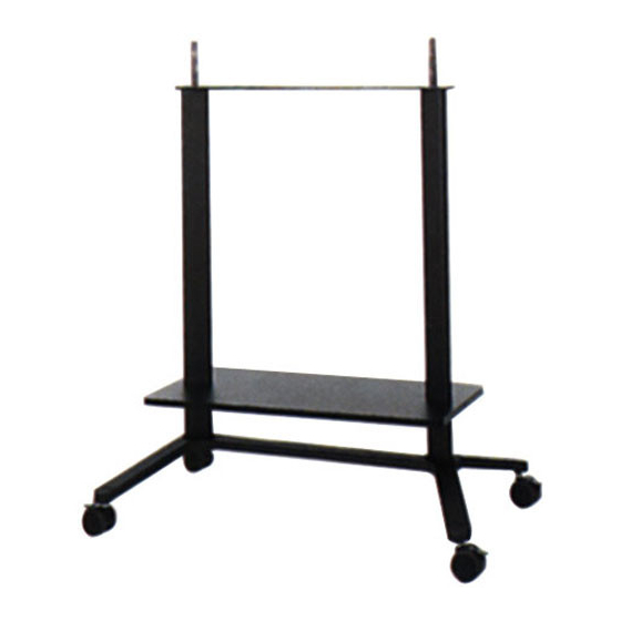
Removing the display unit Remove the two fixing screws from the sides of the holding bracket. 1) Lift the display slightly; 2) Pull the bottom half way to detach the lower insulating spacers; 3) Lift the display away from the holding bracket. Insulating spacer Fixing screws... - Page 23 Mobile stand TY-ST42PF3 Assembly diagram CONTENTS Description ........... 3- Instruction of the installation ...... 3- ......3- 1.Assembling the mobile stand ....... 3- 2.Fixing the display unit to the stand ..........3- 3.Fixing the wiring Removing the display unit......3-...
-
Page 24: Description
Description Installation diagram Units : mm 1020 (40 89 (3 820 (32 400 (15 15° 1030 (40 650 (25... -
Page 25: Instruction Of The Installation
Instruction of the installation Assembling the mobile stand When installing the stand, Insert the supprots into the slots on the upper side of stand base, and provisionally fasten all then fix them from below using the four bolts. bolts and screws first, and then fasten them to complete the assembly. -
Page 26: Fixing The Display Unit To The Stand
Fixing the display unit to the stand Lock the casters before 1) Spread a clean cloth over a level floor or base, and place on it the installing the display unit. display unit face down. Press down the caster 2) Remove the screws and covers. switch to lock the caster. -
Page 27: Fixing The Wiring
Fixing the wiring Insert the accessrory cable straps, evenly spaced, into the appropiate mounting holes in the rear of the support. Cablestraps Cable Bring together the input cables which are connected to the terminals at the bottom of the display unit and secure them with the five cable To loosen cable straps: straps. -
Page 28: Removing The Display Unit
Removing the display unit Loosen and remove the four screws from the display unit. Lift the display unit away from the stand. - Page 29 Wall-hanging bracket (vertical) TY-WK42PV1 Assembly diagram CONTENTS Description ........... 4- Instruction of the installation ...... 4- .... 4- 1.Fixing the wall-hanging bracket to the wall ..4- 2.Fixing the insulating spacers to the display unit 3.Attaching the display unit to ........
-
Page 30: Description
Description Installation diagram Units : mm 1020 * A clearance of at least 100mm at the top of the display unit should be provided. - Page 31 Installation diagram For Multi Screen Units : mm * Installe lower panel unit first.
-
Page 32: Instruction Of The Installation
Instruction of the installation Fixing the wall-hanging bracket to the wall Check the strength of the installation location The wall-hanging bracket The wall-hanging bracket weighs approximately 6kg, and the display unit by has installation holes itself weighs 33kg. Refer to the wall-hanging bracket installation dimensions provided at 24 locations. -
Page 33: Fixing The Insulating Spacers To The Display Unit
Insert and fasten a M6 screw bolt into the center-top hole. If required, use commer- Use a level gauge to correct the alignment of the wall-hanging bracket, c i a l l y a va i l a b l e M 6 and screw bolts into the remaining five holes. -
Page 34: Attaching The Display Unit To The Wall-Hanging Bracket
Attaching the display unit to the wall- hanging bracket Lift the display unit so that the upper insulating spacers at the back may fit into the notched indentation at the top of the wall-hanging Do not lift the display bracket, and then lower the display unit into place. too high or it may come out of the notches in the 1) Lift the display unit slightly and insert the lower insulating spacers... -
Page 35: Removing The Display Unit
Removing the display unit Remove the two fixing screws from the sides of the wall-hanging bracket. 1) Lift the display slightly; 2) At the same time, pull the bottom half way to detach the lower insulating spacers; 3) Lift the display away from the wall-hanging bracket. Fixing srews lower insulating (left and right) -
Page 36: Warning
Warning IF UN OFFICIAL BRACKET IS USED. Do not fix. The display unit with un official bracket by bolts directly, the display unit may damage and possibly electrical interfalance for other electronics equipment. Pan head bolt with hex socket Pan head bolt with Toothed pan washer hex socket Toothed pan washer... - Page 37 Wall-hanging bracket (angled) TY-WK42PR1 Assembly diagram CONTENTS Description ........... 5- Instruction of the installation ...... 5- .... 5- 1.Fixing the wall-hanging bracket to the wall ....5- 2.Adjusting the angle of the display fitting ..5- 3.Fixing the insulating spacers to the display unit 4.Attaching the display unit to ........
-
Page 38: Description
Description Installation diagram Units : mm **310 1020 * A clearance of at least 100mm at the top of the display unit should be provided. ** Installation of the wall-hanging bracket requires a depth of 310 mm. -
Page 39: Instruction Of The Installation
Instruction of the installation Fixing the wall-hanging bracket to the wall Check the strength of the installation location The wall-hanging bracket The wall-handing bracket weighs approximately 6kg, and the wide plasma has installation holes display unit by itself weighs 33kg. Refer to the wall-hanging bracket installation provided at 14 locations. -
Page 40: Adjusting The Angle Of The Display Fitting
Use a level gauge to correct the alignment of the wall-hanging bracket, and screw bolts into the remaining five holes. Provisionally tighten the fixing screws. If the screws protrude After determining the positions and checking them against the bracket, more than 5 mm, it will embed M6 bolts or nuts. -
Page 41: Fixing The Insulating Spacers To The Display Unit
Fixing the insulating spacers to the display unit Spread a clean cloth over a level floor or base, and place on it the display unit face down. Place the display unit face down on top of a Remove the four screws from the display. cloth clean and free from otherforegin particles, Use the accessory tool "Allen key"... -
Page 42: Attaching The Display Unit To The Wall-Hanging Bracket
Attaching the display unit to the wall- hangingbracket Lift the display unit so that the upper insulating spacers at the back may fit into the notched indentation at the top of the wall-hanging bracket, and then lower the display unit into place. After that, lift the display unit slightly and insert the lower insulating spacers at the back of the display unit into the lower cutouts in the Do not lift the display... -
Page 43: Removing The Display Unit
Removing the display unit Remove the two fixing screws from the sides of the wall-hanging bracket. 1) Lift the display unit slightly; 2) At the same time, pull the bottom half way to detach the lower insulating spacers; 3) Lift the display away from the wall-hanging bracket. Insulating spacer Foxing screws (left and right) - Page 44 Celing unit TY-CE42PS1 Assembly diagram CONTENTS Description ........... 6- Instruction of the installation ...... 6- ......... 6- 1.Assembling the ceiling unit ........6- 2.Prepare the ceiling unit ........... 6- 3.Prepare the display ..... 6- 4.Mount the display in the ceiling unit Removing the display unit......
-
Page 45: Description
Description Installation diagram Units : mm (in.) Ceiling board... -
Page 46: Instruction Of The Installation
Instruction of the installation Assembling the ceiling unit Check the strength of the installation location. This ceiling unit weighs approx. 19kg (41.9lbs).The display weights approx. 33kg (72.8lbs) to 45kg (99.2lbs). Refer to the diagram on the right and confirm that the four points for mounting the ceiling unit and display are capable of bearing this weight. - Page 47 Installation the ceiling unit. Attach the ceiling unit (upper section) 1) Before installing the upper section, pull the wiring through the pipe. Use an earthed mains extension lead (not supplied). 2) Make holes in the ceiling using a method appropriate for the ceiling structure and for inserting M12mm bolts.
- Page 48 Attach the ceiling unit (lower section) 1) Match the height adjustment holes on the upper and lower sections to the desired height and refasten in place with two M8 assembly screws. 2) Insert the fixing bolt (M8-100) through the spring washer and then insert it through the uppermost hole in the pipe.
-
Page 49: Prepare The Display
Prepare the display. Install the insulating spacers in the display unit. Lay the display with the screen facing down on a clean blanket or sheet and follow the steps below. 1) Remove the four bolts from the display. 2) In each of the four bolt holes, insert a pan head bolt with hex socket (M8-45), toothed pan washer and insulating spacer (four each, all included). -
Page 50: Mount The Display In The Ceiling Unit
Mount the display in the ceiling unit. Hook the display’s top insulating spacers in the ceiling unit by aligning the display with the notches in the ceiling unit and sliding the display W h e n m o u n t i n g t h e downward. - Page 51 Adjust the ceiling unit's direction. Adjust the angle of the display and fix in place with two fixing bolts (M8-20, included). Fixing bolt (M8-20) x 2 Fixing bolt (M8-20) Adjust the ceiling unit's angle. This ceiling unit can be placed in 7 angles from 0° to 30° in 5° increments. The factory setting is 0°.
- Page 52 Gather the cables. Gather the cables connected to the terminals on the back of the display and fix in place with a cable tie. Cable tie x 2 Cable tie Cable Cable tie Cable...
-
Page 53: Removing The Display Unit
Removing the display unit Remove the two fixing screws (M5) at the left and right sides of the ceiling unit. 1) Lift the lower part of the display, 2) pull outward 3) and lift upward. Insulating spacer Fixing screw (M5) - Page 54 Speakers TY-SP42PM3W TY-SP42PWD3W Assembly diagram CONTENTS Description ........... 7- Safety Precautions ........7- Instruction of the installation ...... 7- ..... 7- 1.Attach the sponges to the speakers ..7- 2.Attach the mounting brackets to the speakers ..7- 3.Attach the speakers to the Wide Plasma Display ......
-
Page 55: Description
Description Installation diagram Units : mm (in.) Left Speaker Right Speaker Safety Precautions Do not suspend the speakers. Personal injury may result if the speakers fall down. Take particular care to ensure the safety of children. These speakers are for use with the Wide Plasma Display only. If connecting them to some other amplifier, make sure that the maximum input to the speakers is within the rated level (8 W). -
Page 56: Instruction Of The Installation
Instruction of the installation Attach the sponges to the speakers. • Attach the sponges to the surfaces which are in contact with the Display. Sponge x 2 • Clean the surfaces before attaching the sponges. Sponges For right For left Attach the mounting brackets to the speakers. -
Page 57: Attach The Speakers To The Wide Plasma Display
Attach the speakers to the Wide Plasma Display. • Insert the hooks on the top and bottom mounting brackets simultaneously into the slots at the rear of the Wide Plasma Display, and then lower the speaker into place. • Attach the left speaker in the same way. Slot Slot Hook... -
Page 58: Connect The Speaker Cables
Connect the speaker cables. • After preparing the ends of the speaker cables, connect them as shown. Speaker cable • Connect the speaker cable for the left speaker in the same way. (20 cm) x 2 • The red cable is for the (+) side and the black cable is for the (-) side. Do not connect the cables to the wrong sides. - Page 59 Matsushita Electric Industrial Co., Ltd. Central P.O. Box 288, Osaka 530-8692, Japan...