Table of Contents
Advertisement
Statement:
This manual is the intellectual property of Foxconn, Inc. Although the
information in this manual may be changed or modified at any time,
Foxconn does not obligate itself to inform the user of these changes.
Trademark:
All trademarks are the property of their respective owners.
Version:
User's Manual V1.1b for C51XEM2AA motherboard.
P/N: 91-181C51M51E-00-G
Symbol description:
Note: refers to important information that can help you to use motherboard
better.
Attention: indicates that it may damage hardware or cause data loss,
and tells you how to avoid such problems.
Warning: means that a potential risk of property damage or physical
injury exists.
More information:
If you want more information about our products, please visit Foxconn's
website:
This product and its accessories are produced after 13th Aug., 2005 and
comply with the W EEE2002/96EC directive.
http://www.foxconnchannel.com
Advertisement
Table of Contents

Related Manuals for Foxconn C51XEM2AA


Summary of Contents for Foxconn C51XEM2AA
-
Page 1: More Information
This manual is the intellectual property of Foxconn, Inc. Although the information in this manual may be changed or modified at any time, Foxconn does not obligate itself to inform the user of these changes. Trademark: All trademarks are the property of their respective owners. -
Page 2: Declaration Of Conformity
HON HAI PRECISION INDUSTRY COMPANY LTD 66 , CHUNG SHAN RD., TU-CHENG INDUSTRIAL DISTRICT, TAIPEI HSIEN, TAIWAN, R.O.C. declares that the product Motherboard C51XEM2AA is in conformity with (reference to the specification under which conformity is declared in accordance with 89/336 EEC-EMC Directive) þ... - Page 3 Declaration of conformity Trade Name: Foxconn Model Name: C51XEM2AA Industry Inc. Responsible Party: Address: 458 E. Lambert Rd. Fullerton, CA 92835 Telephone: 714-738-8868 Facsimile: 714-738-8838 Equipment Classification: FCC Class B Subassembly Type of Product: Motherboard Manufacturer: HON HAI PRECISION INDUSTRY...
-
Page 4: Table Of Contents
Table of Contents Chapter Product Introduction Main Features ..................... 2 Highlight Features ..................4 Layout ......................7 Rear Panel Ports ..................8 Installation Instructions Chapter CPU ......................11 Memory ....................14 Power Supply ................... 16 Other Connectors ..................17 Expansion Slots ..................21 Jumpers .................... - Page 5 Table of Contents Chapter Driver CD Introduction Utility CD content ..................47 Installing drivers ..................48 Installing Utilities ..................48 Chapter Directions for Bundled Software NVIDIA nTune 4.0 ..................50 Fox LiveUpdate ..................60 Media Shield RAID Manager ..............67 Network Access Manager ................
- Page 6 Attention: 1. Attach the CPU and heatsink using silica gel to ensure full contact. 2. It is suggested to select high-quality, certified fans in order to avoid damage to the motherboard and CPU due high temperatures. 3. Never turn on the machine if the CPU fan is not properly installed. 4.
- Page 7 This manual is suitable for motherboard of C51XEM2AA. Each motherboard is carefully designed for the PC user who wants diverse features. -L with onboard 10/100M LAN (Default is omitted.) -K with onboard Gigabit LAN -6 with 6-Channel audio (Default is omitted.)
-
Page 8: Highlight Features
Chapter T han k you fo r b uying Fo xco n n’ s C 5 1X EM 2 AA series motherboard. This series of motherboard is one of our new products, offers superior performance, and uses the advanced NVIDIA nForce ®... -
Page 9: Main Features
Chapter 1 Product Introduction Main Features Size · ATX form factor of 12 inch x 9.6 inch Microprocessor · Supports AMD ® Socket AM2 Athlon 64 X2 Dual-Core, Athlon 64 FX, Athlon 64 and Sempron processor · Supports HyperTransport up to 2000MT/s ·... -
Page 10: Chapter 1 Product Introduction
Chapter 1 Product Introduction Onboard 1394 (-E ) (optional) · Support hot plug · Two 1394a port with rate of transmission at 400 Mbps · One 1394b port with rate of transmission at 800 Mbps Onboard Audio (-8) · Supports 8-channel audio ·... - Page 11 Chapter 1 Product Introduction Hightlight Features Engineered for Enthusiasts NVIDIA nForce ® 590 SLI media and communication processors (MCPs) deliver the tools and performance enthusiasts demand. When combined with select NVIDIA GeForce graphics cards and other system components, you get automatic access to faster bus speeds.
- Page 12 Chapter 1 Product Introduction DiskAlert System The event of a disk failure, MediaShield users see an image that highlights which disk has failed to make it easier to identify, replace, and recover. RAID Morphing MediaShield allows users to change their current RAID set-up to another configuration in a one-step process called morphing.
- Page 13 Chapter 1 Product Introduction clear phone conversations and online gaming performance you expect. NVIDIA FirstPacket technology assures your game data, VoIP conversations, and large file transfers are delivered according to preferences set by you in an intuitive wizard. NVIDIA DualNet technology ®...
-
Page 14: Layout
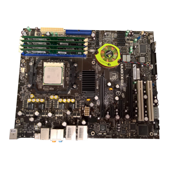
Chapter 1 Product Introduction Layout 14 15 17 18 19 20 1. 8-pin ATX_12V Power Connector 14. MCP Fan Connector 2. C51XE 15. Front Panel Connector 3. PCI Express x16 Slots 16. Clear CMOS Jumper 17. Serial ATA II Connectors 4. -
Page 15: Rear Panel Ports
Chapter 1 Product Introduction Rear I/O Ports This motherboard provides the ports as below: 1. PS/2 Mouse Port This port is used to connect a PS/2 mouse. 2. PS/2 Keyboard Port This port is used to connect a PS/2 keyboard. 3. - Page 16 Chapter 1 Product Introduction 6. Line in, Line out, Microphone, Rear, LEF/CEN Jacks & Optical S/PDIF Out Port Port 2-channel 4-channel 6-channel 8-channel Blue Line In Line In Line In Line In Green Line Out Front Speaker Out Front Speaker Out Front Speaker Out Pink Mic In...
- Page 17 Chapter 1 Product Introduction Chapter This chapter introduces the hardware installation process, in- cluding the installation of the CPU, memory, power supply, slots, and pin headers, and the mounting of jumpers. Cau- tion should be exercised during the installation of these modules.
-
Page 18: Chapter Installation Instructions Cpu
Chapter 2 Installation Instructions This motherboard supports AMD Socket AM2 Athlon 64 X2 Dual-Core, Athlon 64 FX, Athlon 64 and Sempron processor with Hyper-Transport Technology. Attention: The CPU pins must be properly aligned with the holes in the socket, otherwise the CPU may be damaged. For the detailed CPU vendor list qualified on this motherboard, please visit the website: http://www.foxconnchannel.com... - Page 19 Chapter 2 Installation Instructions Installation of CPU Fan New technology allows processors to run at higher and higher frequencies. To avoid problems arising from high-speed operation, for example, overheat- ing, you need to install the proper fan. The following procedure is provided for reference only, please refer to your CPU fan user guide for the actual procedure.
- Page 20 Chapter 2 Installation Instructions 3. Place the cooling set onto the re- 4. Align the other end of the reten- tention mechanism. Attach one end tion bracket to fasten the cooling of the retention bracket to retention set on the top of the retention mechanism.
-
Page 21: Memory
Chapter 2 Installation Instructions Memory This motherboard includes four 240-pin slots with 1.8V for DDR2. These slots support 256 Mb, 512 Mb and 1 Gb DDR2 technologies for x8 and x16 devices, and support dual channel DDR2 memory technology up to 10.7GB/s. You must install at least one memory bank to ensure normal operation. - Page 22 Chapter 2 Installation Instructions Warning : Be sure to unplug the AC power supply before adding or removing expansion cards or other system peripherals, especially the memory devices, otherwise your motherboard or the system memory might be seriously damaged. For the detailed memory support list on this motherboard, please visit the website: http://www.foxconnchannel.com...
-
Page 23: Power Supply
Chapter 2 Installation Instructions Power Supply This motherboard uses an ATX power supply. In order to avoid damaging any devices, make sure that they have been installed properly prior to connecting the power supply. 24-pin ATX Power Connector 24-pin ATX power connector: PWR1 RSVD PS-ON + 5 V... -
Page 24: Other Connectors
Chapter 2 Installation Instructions Other Connectors This motherboard includes connectors for FDD devices, IDE devices, Serial ATA devices, USB devices, and others. FDD Connector: FLOPPY This motherboard includes a standard FDD connector, supporting 360K, 720K, 1.2M, 1.44M, and 2.88M FDDs. IDE Connector: PIDE The IDE connector supports Ultra ATA 133/100/66 IDE hard disk drives. - Page 25 Chapter 2 Installation Instructions Front Panel Connector: FP1 PW R SW Empt y PW RL ED This motherboard includes one connector for con- necting the front panel switch and LED indicators. HD-L ED R E S E T HDD LED Connector (HDD-LED) The connector connects to the case’s HDD indicator LED indicating the activity status of hard disks.
-
Page 26: Installation Instructions
Chapter 2 Installation Instructions Serial ATA II Connectors: SATA_1, SATA_2, SATA_3, SATA_4, SATA_5, SATA_6 The Serial ATA II connector is used to connect the Serial ATA II device to the motherboard. These connectors support the thin Serial ATA II cables for primary storage devices. - Page 27 Chapter 2 Installation Instructions IEEE 1394a Connector: F_1394_1 (optional) Empty The 1394 expansion cable can be connected to either +12V +12V the front (provided that the front panel of your chassis TPB - TPB + is equipped with the appropriate interface) or real TPA - TPA + panel of the chassis.
-
Page 28: Expansion Slots
Chapter 2 Installation Instructions Expansion Slots This motherboard includes two 32-bit master PCI bus slots, one PCI Express x 1 slot, one PCI Express x4 slot and two PCI Express x 16 slots. PCI Slots The expansion cards can be installed in the two PCI slots. PCI slots support cards such as a LAN card, USB card, SCSI card and other cards that comply with PCI specifications. -
Page 29: Jumpers
Chapter 2 Installation Instructions Jumpers The users can change the jumper settings on this motherboard if needed. This section explains how to use the various functions of this motherboard by chang- ing the jumper settings. Users should read the following content carefully prior to modifying any jumper settings. -
Page 30: Bios Description
Chapter 3 BIOS Description Chapter This chapter tells how to change system settings through the BIOS Setup menus. Detailed descriptions of the BIOS pa- rameters are also provided. This chapter includes the following information: Enter BIOS Setup Main Menu Standard CMOS Features Advanced BIOS Features Advanced Chipset Features Integrated Peripherals... -
Page 31: Enter Bios Setup
Chapter 3 BIOS Description Enter BIOS Setup The BIOS is the communication bridge between hardware and software, correctly setting up the BIOS parameters is critical to maintain optimal system performance. Power on the computer, when the following message briefly appears at the bottom of the screen during the POST (Power On Self Test), press <Del>... - Page 32 Chapter 3 BIOS Description Advanced BIOS Features The advanced system features and boot sequence can be setup through this menu. Advanced Chipset Features Optimize system performance through this menu. Configure clocks, voltages, memory timings, and more. Integrated Peripherals Onboard peripherals such as RAID, USB, and MAC control can be setup through this menu.
- Page 33 Chapter 3 BIOS Description NVIDIA LinkBoost <STATUS> This status appears at the bottom of the BIOS screen. <STATUS> can be: Detected: System detects an LinkBoost capable components. Not Detected: The LinkBoost components are not detected. SLI-Ready Memory <STATUS> This status appears at the bottom of the BIOS screen. <STATUS> can be: Enabled: SLI-Ready memory detected and enabled.
-
Page 34: Standard Cmos Features
Chapter 3 BIOS Description Standard CMOS Features This sub-menu is used to set up the standard CMOS features, such as the date, time, HDD model and so on. Use the arrow keys select the item to set up, and then use the <PgUp> or <PgDn> keys to choose the setting values. Standard CMOS Features Menu Date This option allows you to set the desired date (usually as the current day) with... - Page 35 Chapter 3 BIOS Description Award (Phoenix) BIOS can support 3 HDD modes: CHS, LBA and Large or Auto mode. For HDD<528MB For HDD>528MB & supporting LBA (Logical Block Addressing) Large For HDD>528MB but not supporting LBA Auto Recommended mode Drive A This option allows you to select the kind of FDD to be installed, including “None”, [360K, 5.25 in], [1.2M, 5.25 in], [720K, 3.5 in], [1.44M, 3.5 in] and [2.88 M, 3.5 in].
-
Page 36: Advanced Bios Features
Chapter 3 BIOS Description Advanced BIOS Features Advanced BIOS Features Menu vRemovable Device Priority This option is used to select the priority for removable device startup. After pressing <Enter>, you can select the removable device using the <PageUp>/ <PageDn> or Up/Down arrow keys, and change the removable device priority using <+>... - Page 37 Chapter 3 BIOS Description vBoot Up NumLock Status This item defines if the keyboard Num Lock key is active when your system is started. vSecurity Option W hen it is set to “Setup”, a password is required to enter the CMOS Setup screen;...
-
Page 38: Advanced Chipset Features
Chapter 3 BIOS Description Advanced Chipset Features Use this section to control chipset features, specifically clocks, voltages, and memory timings. Advanced Chipset Features Menu vSystem Clocks Use this menu to control system clocks (see System Clocks section below). vSystem Voltages Use this menu to control system voltages (see System Voltages section below). - Page 39 Chapter 3 BIOS Description vLoad timing/voltage settings Load timing and voltage settings from a profile. vSave timing/voltage settings Save timing and voltage settings to a profile. System Clocks menu Frequency Settings vRef Clock (HTT) Reference clock frequency. vCPU Multiplier The value of the CPU multiplier. vPCIe Bus, Slot 1 The frequency of the PCI-Express Bus, Slot 1.
- Page 40 Chapter 3 BIOS Description vnForce SPP ß nForce MCP The HT multiplier from the MCP to the SPP. HT Width vCPU ß à nForce SPP The HT width between the CPU and the SPP. vnForce SPP ßà nForce MCP The HT width between the SPP and the MCP. System Voltages menu vCPU Voltage to the CPU...
- Page 41 Chapter 3 BIOS Description Memory Configuration menu vSLI-Ready Memory Enable memory settings that are SLI-Ready (only functional with DRAM that is SLI-Ready). vMemory Timings Use this menu to control memory timings (see Memory Timings section below). vDrive Strength setting Use this menu to control drive strength settings (see Drive Strength set- tings section below).
- Page 42 Chapter 3 BIOS Description vCKE base power down mode Enable or disable CKE base power down mode. vCKE power down control CKE power down mode selection. It should be set to “per channel” for non mobile systems. vMemclock tri-stating Memclock tri-stating during C3 and Alt VID. vMemory Hole remapping Enable or disable memory hole remapping.
- Page 43 Chapter 3 BIOS Description vtRAS Minimum RAS# active time vCommand Per Clock (CMD) Command timing setting (per clock unit). Advance Memory Settings vtRRD RAS# to RAS# delay of different banks. vAsyncLat Max round trip latency from the CPU to the DRAM. vtRC RAS# to RAS# or auto refresh time of the same bank.
- Page 44 Chapter 3 BIOS Description Drive Strength settings menu vDRAM driver weak mode DRAM data drive strength on DRAM. vCKE drive strength Drive strength of the CKE pins. vCS drive strength Drive strength of the CS and ODT pins. vMA drive strength Drive strength of the Address, RAS, CAS, W E, and parity pins.
-
Page 45: Integrated Peripherals
Chapter 3 BIOS Description Integrated Peripherals Integrated Peripherals Menu vIDE Function Setup Use this menu to setup the data flow control for IDE. vRAID Config Use this menu to enable or disable SATA RAID. vUSB Config Use this menu to setup USB interface. vMAC Config Use this menu to turn off MAC. -
Page 46: Power Management Setup
Chapter 3 BIOS Description Power Management Setup Power Management Setup Menu vACPI function ACPI stands for “Advanced Configuration and Power Interface”. ACPI is a standard that defines power and configuration management interfaces be- tween an operating system and the BIOS. In other words, it is a standard that describes how computer components work together to manage system hardware. - Page 47 Chapter 3 BIOS Description vWOL(PME#) From Soft-Off This item is used to set the system to wake-up on LAN. vWOR(RI#) From Soft-Off This item is used to set the system to wake-up on ring. vAMD Cool ‘n’ Quiet[tm] Use this option to enable or disable AMD Cool ‘n’ Quiet Technology.
-
Page 48: Pnp/Pci Configurations
Chapter 3 BIOS Description PnP/PCI Configurations PnP/PCI Configurations Menu Init Display First This option is used to set which display device will be used first when your PC starts up. vReset Configuration Data This option is used to set whether the system is permitted to automatically distribute IRQ, DMA, and I/O addresses each time the machine is turned on. -
Page 49: System Monitor
Chapter 3 BIOS Description System Monitor System Monitor Menu Temperature values vSystem The temperature of the system. vCPU The temperature of the CPU. vBoard The temperature of the motherboard. Voltage values vCPU The voltage of the CPU. vMemory The voltage of the Memory. v+3.3V The voltage of the +3.3V . - Page 50 Chapter 3 BIOS Description vnForce MCP The voltage of the nForce MCP chip. vnForce SPP The voltage of the nForce SPP chip. vHT CPU <-> nForce SPP The voltage of the HT between the CPU and the nForce SPP chip. v+Vbat The voltage of +Vbat.
-
Page 51: Load Defaults
Chapter 3 BIOS Description Load Defaults The BIOS defaults sets the basic system functions that ensure system stability. If the system is NVIDIA LinkBoost enabled, the default settings are the LinkBoost settings. If your computer cannot POST properly, you should load the Defaults to restore the original settings. -
Page 52: Exit Without Saving
Chapter 3 BIOS Description Exit Without Saving If you select this option and press <Enter>, the following message will appear in the center of the screen: Quit Without Saving (Y/N)?N Press <Y> to exit CMOS without saving your modifications; press <N> or <ESC> to return to the main menu. -
Page 53: Chapter 4 Driver Cd Introduction
Chapter 4 Driver CD Introduction Chapter The utility CD that came with the motherboard contains use- ful software and several utility drivers that enhance the motherboard features. This chapter includes the following information: Utility CD content Start to install drivers... -
Page 54: Utility Cd Content
B. Foxconn LiveUpdate C. Adobe Acrobat Reader D. Norton Internet Security 3. User Manuals Click here to browse all user manuals content. 4. Browse CD Click here to browse CD content. 5. Foxconn Website Click here to visit Foxconn website. -
Page 55: Installing Drivers
Chapter 4 Driver CD Introduction Installing Divers Click the drivers that you want to install and begin the setup steps. Click here Installing Utilities You can select the utilities that you want to install and begin the setup steps. Click here... - Page 56 Chapter 4 Driver CD Introduction Chapter This chapter will introduce how to use attached software. This chapter provides the following information: NVIDIA nTune 4.0 Fox LiveUpdate MediaShield RAID Manager Network Access Manager...
-
Page 57: Directions For Bundled Software
Chapter 5 Directions for Bundled Software NVIDIA nTune 4.0 NVIDIA nTune is a utility for accessing, monitoring, and adjusting your system components, including temperature and voltages, with clear, user-friendly con- trol panels. Overclock your system for highest performance or underclock it for ®... - Page 58 Chapter 5 Directions for Bundled Software Side Panel The nTune 4.0 Side Panel is located to the left of every screen in nTune and provides access to help, recently used tasks, related tasks, and pending changes. Each of these are explained more below.
- Page 59 Chapter 5 Directions for Bundled Software nTune Task View After selecting the nTune category, the task list is presented. Each of the tasks are grouped into two categories: System Performance and System Diagnostics. The tasks available under these categories include: Performance tuning wizard Manage profile rules Adjust speeds and timings...
- Page 60 Chapter 5 Directions for Bundled Software The Quick method takes approximately 20 minutes to run while it adjusts system bus speeds and parameters. It first saves current bus speeds as the Default.npe file. After performing a CPU intensive micro-benchmark, to ensure the system tem- perature stays low while fan noise is reduced, it saves a second file named Silent.
- Page 61 Chapter 5 Directions for Bundled Software Manage Profile Rules This task is used to assign specific applications to specific profiles. Each time the application is launched, the assigned profile will go into effect. The profile menu may be pulled down to select a different profile. The list will be built from profiles currently existing in the profile directory.
- Page 62 Chapter 5 Directions for Bundled Software Diagnose System Performance This task is used to quickly diagnose potential system performance issues and relay valuable troubleshooting data to technical support. nTune performs a series of quick checks to identify probably causes of performance issues and then creates a list of the results, providing recommendations for improvements.
- Page 63 Chapter 5 Directions for Bundled Software System Stability Category To access System Stability related features, select the System Stability category. System Stability Task View After selecting the System Stability category, a task list is presented. Under the Diagnostics heading, the tasks available include “View the system status” and “Perform a stability test”.
- Page 64 Chapter 5 Directions for Bundled Software View System Status The status of the system including current system clock speeds, system tempera- tures, memory timings, and system voltages is presented with View System Status. Specific settings that can be checked include: CPU speed and multiplier HyperTransport link multiplier PCI Express bus speed...
- Page 65 Chapter 5 Directions for Bundled Software The following system components can be verified for stability: CPU, Memory, PCI-E bus, Disk, Network, and GPU. Each of these or all of these, depending on what components are selected, can be tested using a selected profile or current system settings.
- Page 66 Chapter 5 Directions for Bundled Software NVMonitor displays performance for individual components including CPU, Network, Disk, and Memory. Bus speeds for CPU, Memory, HyperTransport (HT), and PCI Express (PCX) can be monitored along with temperature and voltages. The current profile is displayed alongside the SMART hard drive status if that has been enabled in the system BIOS.
-
Page 67: Fox Liveupdate
Chapter 5 Directions for Bundled Software Fox LiveUpdate Fox LiveUpdate is a useful utility for backuping and updating the system BIOS, drivers and utilities by local or online. Supported Operating Systems: -W indows 2000 -Windows XP (32-bit and 64-bit) -W indows 2003 (32-bit and 64-bit) Using Fox LiveUpdate: 1.1 Local Update - BIOS Info. - Page 68 Chapter 5 Directions for Bundled Software 1.2 Local Update - Backup This page lets you backup your system BIOS. Click “Backup”, then give a name. Click “Save” to finish the backup operation. Key in a BIOS name Click here 1.3 Local Update - Update This page lets you update your system BIOS from Internet.
- Page 69 Chapter 5 Directions for Bundled Software 2.1 Online Update - Update BIOS This page lets you update your system BIOS from Internet. Click “start”, it will search the new BIOS from Internet. Then follow the wizard to finish the update operation.
- Page 70 Chapter 5 Directions for Bundled Software 2.2 Online Update - Update Driver This page lets you update your system drivers from Internet. Click “start”, it will search the new drivers from Internet. Then follow the wizard to finish the update operation.
- Page 71 Chapter 5 Directions for Bundled Software 2.3 Online Update - Update Utility This page lets you update utilities from Internet. Click “start”, it will search the new utilities from Internet. Then follow the wizard to finish the update operation. Click here Current information Search new utilities from Internet...
- Page 72 Chapter 5 Directions for Bundled Software 3.1 Configure - option This page lets you set auto search options. After your setting, the utility will start searching and related information will show on the task bar. Click here Set auto search options Select search which kind of versions...
- Page 73 Chapter 5 Directions for Bundled Software 3.2 Configure - System This page lets you set the backup BIOS location and change different skin of the utility. Click here Set the location of download files or auto backup BIOS Select different skin of the software Reset to default value Determine if the Fox LiveUpdate...
-
Page 74: Mediashield Raid Manager
Chapter 5 Directions for Bundled Software MediaShield RAID Manager MediaShield RAID Manager allows a user to: Create RAID Arrays View RAID Arrays Delete RAID Arrays Set up a spare RAID disk Morph RAID Arrays Hot Plug Array The following sections give an overview of how to create/view/delete an array, and how to set up a spare RAID disk. - Page 75 Chapter 5 Directions for Bundled Software 1. Click Next to go to the following screen: Figure 2. MediaShield Select-Configuration Screen Note: You will only see this screen if you have less than 4 free disks in the system. If there are 4 or more free disks available, you will proceed to directly to custom setup.
- Page 76 Chapter 5 Directions for Bundled Software Figure 3. Creating a Striped Array To select a Mirrored Array, select “Mirroring” as RAID mode and leave Stripe Size as default. To select a Striped Mirror Array, select “Stripe Mirroring” as RAID Mode and leave Stripe Size as default.
- Page 77 Chapter 5 Directions for Bundled Software Select the disks you want to include in the Stripe set. Follow the next couple to complete creating the Array. View RAID Arrays To view your RAID configuration from Windows, launch the MediaShield RAID Man- agement utility by double-clicking MediaShield.
- Page 78 Chapter 5 Directions for Bundled Software Follow the next couple of screens to complete Deleting the Array. As shown in Figure 7, the array has been deleted and we see only free disks. Figure 7. RAID Array deleted Setting Up a Spare RAID Disk You can designate a hard drive to be used as a spare drive for a RAID 1, RAID 0+1 or RAID 5 array2.
- Page 79 Chapter 5 Directions for Bundled Software Assigning a Free Disk To mark a disk as free, or not a part of any array, do the following: 1. Enter the system BIOS setup and make sure that the drive that you want to mark as free is RAID enabled.
- Page 80 Chapter 5 Directions for Bundled Software Figure 9. Dedicating a Disk to an Array 2. Select Designate Spare from the menu to launch the Spare Disk Allocation Wizard. Figure 10. Disk Allocation Wizard 3. Click Next. The Free Disk Selection page appears.
- Page 81 Chapter 5 Directions for Bundled Software Figure 9. Dedicating a Disk to an Array 4. From the Free Disk Selection page, select a free disk. This disk will be designated to the array.
-
Page 82: Network Access Manager
Chapter 5 Directions for Bundled Software Network Access Manager The NVIDIA ® ForceWare ® Network Access Manager (NAM) application helps you easily configure and control NVIDIA networking hardware and software, gather statistics, and monitor logs. W hen you launch NAM for the first time, the following GUI appears. Settings for Network Access Manager As shown in the previous screenshot, these entries are available in NMA. - Page 83 Chapter 5 Directions for Bundled Software vTeaming: Teaming controls load balancing and fail-over between two Ethernet ports. vLogs: This setting enables/disables logging of various setting, such as Ethernet and teaming. vTCP/IP Acceleration: This entry enables or disables TCP/IP acceleration and configuration.
- Page 84 Chapter 5 Directions for Bundled Software Teaming What It Does Teaming is the ability to provide load balancing and fail-over between two Ethernet ports. W hen this feature is enabled and configured properly, one IP address is visible on the network, and all networking traffic is distributed between the two Ethernet ports, depending on the Teaming mode of operation selected, as ex- plained in the following topics.
- Page 85 Chapter 5 Directions for Bundled Software Failover Only Load balancing (LB) is frequently used in conjunction with “failover” (FO), although it is possible to use failover alone. For instance, one Ethernet interface might be dedicated as a “hot standby” in the event that the primary Ethernet interface fails. Team Mode: IEEE 802.3ad In 802.3ad, all the team members share a common MAC address.
- Page 86 Chapter 5 Directions for Bundled Software TCP/IP Acceleration When TCP/IP acceleration is enabled and configured properly, most of the TCP/IP traffic is processed in hardware by the media and communications (MCP) chip. The advantage this technology offers is that it lowers the CPU utilization, which leads to overall better system performance since the CPU has more free cycles to focus on other tasks.
- Page 87 Chapter 5 Directions for Bundled Software Administration In the Administration area, you can change various parameters of the Web GUI, manage remote access, reset the software to its default setting, and more. Summary Network Access Manager is an easy-to-use Web interface that provides all the networking configuration, monitoring, and logging that users demand.
-
Page 88: Chapter 6 Appendix
Chapter 6 Appendix Chapter This chapter will introduce how to use attached software. This chapter provides the following information: NVIDIA SLI technology NVIDIA RAID Audio Configuration On board LED Code Table... -
Page 89: Nvidia Sli Technology
Chapter 6 Appendix NVIDIA SLI Technology 1. Introduction NVIDIA (Scalable Link Interface) technology takes advantage of the increased ® bandwidth of the PCI Express bus architecture, and features intelligent hardware and software solutions to deliver earth-shattering PC performance in a multi NVIDIA GPU solution. - Page 90 Chapter 6 Appendix Step2. Connect power extension cable to the graphics card power connector and power supply connector. Power Extension cable Step 3. Install the SLI Bridge Board to the goldfingers on each graphics card. Make sure that the connector is firmly in place. Step 4.
- Page 91 Chapter 6 Appendix Step 7. Right-click the mouse --> Select “Properties”--> Select “Setting” --> Click “Advanced” --> Select “GeForce xxxx xxx” --> Click “SLI multi-GPU” --> Click “Enable SLI multi-GPU”.
-
Page 92: Nvidia Raid
Chapter 6 Appendix NVIDIA RAID RAID Arrays This section describes the following types of RAID arrays that NVIDIA RAID supports: RAID 0 RAID 0 defines a disk striping scheme that improves the disk read and write times for many applications. vRAID 1 RAID 1 defines techniques for mirroring data. -
Page 93: Features And Benefits Summary
Chapter 6 Appendix Additional RAID Features NVIDIA RAID offers the following additional features: vFree Disk and Dedicated Spare Disk A Free Disk or Dedicated Disk can be automatically used in case one drive of a fault-tolerant array fails. NVIDIA RAID defines a fault-tolerant array as either RAID 1, RAID 0+1, or RAID 5. -
Page 94: Basic Configuration Instructions
Chapter 6 Appendix Basic Configuration Instructions The following are the basic steps for configuring NVIDIA RAID: Non-Bootable RAID Array 1. Choose the hard disks that are to be RAID enabled in the system BIOS. 2. Specify the RAID level, either Mirroring (RAID 1), Striping (RAID 0), Stripe Mirroring (RAID 0+1), or Spanning (JBOD) and create the desired RAID array. -
Page 95: Setting Up The Bios
Chapter 6 Appendix Setting Up the BIOS 1. Start up the computer, then press Delete to enter the BIOS setup. Use the arrow keys to select Integrated Peripherals, then press Enter. 2. Use the arrow keys to select the RAID Config, then press Enter. 3. -
Page 96: Entering The Raid Bios Setup
Chapter 6 Appendix Entering the RAID BIOS Setup 1. After rebooting your PC, wait until you see the RAID software prompting you to press F10. The RAID prompt appears as part of the system POST and boot process prior to loading OS. 2. - Page 97 Chapter 6 Appendix In the example above, 1.0.M means the hard drive is attached to Adapter 1, Channel 0, and the drive is set to Master. The following is a list of all possible combinations: Parallel ATA 0.0.M Adapter 0, Channel 0, Master 0.0.S Adapter 0, Channel 0, Slave Serial ATA...
- Page 98 Chapter 6 Appendix • Assigning the Disks The disks that you enabled from the RAID Config BIOS setup page appear in the Free Disks block. These are the drives that are available for use as RAID array. To designate a free disk to be used as a RAID array: 1.
- Page 99 Chapter 6 Appendix 2. Press Y if you want to wipe out all the data from the RAID array, otherwise press N. You must choose Yes if the drives were previously used as RAID drives. The Array List window appears, where you can review the RAID arrays that you have set up.
-
Page 100: Nvidia Raid Utility Installation
Chapter 6 Appendix NVIDIA RAID Utility Installation Installing the NVIDIA RAID Software Under Windows (for Non-bootable RAID Array) This section describes how to setup the application and install the RAID software . 1. Start the nForce Setup program to open the NVIDIA Windows nForce Drivers page. - Page 101 Chapter 6 Appendix Installing the RAID Driver (for bootable RAID Array) 1. Create an F6 install floppy by using the “-x” option, then copy all files in “...\IDE\WinXP\sataraid” to a floppy disk. (For W indows 2000, substitute “W in2K” in the path.) After you complete the RAID BIOS setup, boot from the W indows CD, and the Windows Setup program starts.
- Page 102 Chapter 6 Appendix 4. Press Enter to continue with operating system Installation. Be sure to copy the files from the floppy is complete, then take out the floppy. 5. Follow the instructions on how to install operating system. During the GUI portion of the installation you might be prompted to click Yes to install the RAID driver.
-
Page 103: Initializing And Using The Disk Array
Chapter 6 Appendix Initializing and Using the Disk Array The RAID array is now ready to be initialized under Windows. 1. Launch Computer Management by clicking “Start” —> “Settings” —> “Control Panel” then open the “Administrative Tools” folder and double click on “Computer Management”. -
Page 104: Audio Configuration
Chapter 6 Appendix Audio Configuration The ALC882 provide 10 channels of DAC that simultaneously support 7.1 sound playback, plus 2 channels of independent stereo sound output (multiple stream- ing) through the Front-Out-Left and Front-Out-Right channels. Flexible mixing, mute, and fine gain control functions provide a complete integrated audio solu- tion for next generation multimedia PCs. - Page 105 Chapter 6 Appendix 4. Sound Effect Introduction Allows you to set your listening environment, adjust the equalizer, set the Karaoke, or select pre-programmed equalizer settings. 1. Click here 2. Select environment 3. Set equalizer 4. Click OK 5. Mixer Introduction Allows you to set audio output and audio input volume.
- Page 106 Chapter 6 Appendix 6. Audio I/O Introduction Allows you to configure your input/output settings. 1. Click here 2. Select channel configuration 3. Test 4. Click OK 7. Microphone Introduction Allows you to configure your input/output settings and to check if your audio devices are connected properly.
- Page 107 Chapter 6 Appendix 8. 3D Audio Demo Introduction This option gives you a demostration of the 3D audio feature. 1. Click here 2. Click here 3. Test your setting 4. Click OK...
-
Page 108: On Board Led Code Table
Chapter 6 Appendix On board LED Code Table Code(hex) Name Description Reserved Jumps to E000 segment Execution of POST routines in E000 Early Superio Init Early Initialized the super IO Reserved Blank video Reset Video controller Reserved Init KBC Keyboard controller init KB test Test the Keyboard Reserved... - Page 109 Chapter 6 Appendix Code(hex) Name Description Early PM Early PM initialization Reserved Re-initial KB Load keyboard matrix Reserved HPM init Init Heuristic Power Management (HPM) Reserved Program chipset Early Programming of chipset registers Init PNP Init PNP Shadow VBIOS Shadow system/video BIOS Clock Gen Init onboard clock generator and sensor...
- Page 110 Chapter 6 Appendix Code(hex) Name Description Test Timer Test 8254 Timer 0 Counter 2. Reserved Test 8259-1 Mask Verify 8259 Channel 1 masked interrupts by alternately turning off and on the interrupt lines. Reserved Test 8259-2 Mask Verify 8259 Channel 2 masked interrupts by alternately turning off and on the interrupt lines.
- Page 111 Chapter 6 Appendix Code(hex) Name Description Memory Test Test all memory of memory above 1MB using Virtual 8086 mode, page mode and clear the memory Reserved Reserved CPU display Detect CPU speed and display CPU vendor specific version string and turn on all necessary CPU features Reserved PnP Init Display...
- Page 112 Chapter 6 Appendix Code(hex) Name Description Initialize Floppy Initialize floppy disk drive Reserved FDD install Install FDD and setup BIOS data area parameters Reserved Reserved Reserved Initialize Hard Drive Initialize hard drive controller Reserved Detect HDD IDE device detection Reserved Detect serial ports Initialize serial ports Reserved...
- Page 113 Chapter 6 Appendix Code(hex) Name Description Reserved IRQ12 Enable Enable IRQ12 if mouse present Reserved Reserved Reserved Boot Medium Read Detect and store boot partition head and cylinders values in RAM Final Init Final init for last micro details before boot NumLock Set NumLock status according to...
- Page 114 Chapter 6 Appendix Code(hex) Name Description Set Top-Of-Memory Set Top-Of-Memory registers Late SLAM table Late SLAM table Previous Power State Previous Power State SLAM SLAM table table Hardware W orkarounds Hardware W orkarounds NVMM Restore, and exit NVMM NV Memory Test NV Memory Test ERROR handler ERROR handler...