Table of Contents
Advertisement
Advertisement
Table of Contents

Related Manuals for ASROCK QC5000-ITX/WiFi


Summary of Contents for ASROCK QC5000-ITX/WiFi
- Page 1 QC5000-ITX/WiFi QC5000-ITX User Manual...
-
Page 2: Copyright Notice
(including damages for loss of profits, loss of business, loss of data, interruption of business and the like), even if ASRock has been advised of the possibility of such damages arising from any defect or error in the documentation or product. -
Page 3: Table Of Contents
Chapter 1 Introduction Package Contents Specifications Unique Features Motherboard Layout I/O Panel WiFi-802.11n Module and ASRock WiFi 2.4GHz Antenna (for QC5000-ITX/WiFi only) Chapter 2 Installation Installing Memory Modules (DIMM) Expansion Slots (PCI Express Slots) Jumpers Setup Onboard Headers and Connectors... - Page 4 OC Tweaker Screen Advanced Screen 4.4.1 CPU Configuration 4.4.2 Chipset Configuration 4.4.3 Storage Configuration 4.4.4 Super IO Configuration 4.4.5 ACPI Configuration 4.4.6 USB Configuration 4.4.7 Trusted Computing Tools Hardware Health Event Monitoring Screen Boot Screen Security Screen Exit Screen...
-
Page 5: Chapter 1 Introduction
If you require technical support related to this motherboard, please visit our website for specific information about the model you are using. You may find the latest VGA cards and CPU support list on ASRock’s website as well. ASRock website http://www.asrock.com. -
Page 6: Specifications
1.2 Specifications Platform • Mini-ITX Form Factor • All Solid Capacitor design • High Density Glass Fabric PCB • AMD FT3 Kabini A4-5000 Quad-Core APU Memory • 2 x DDR3 DIMM Slots • Supports DDR3 1600/1333/1066 non-ECC, un-buffered memory • Max. capacity of system memory: 32GB (see CAUTION1) Expansion • 1 x PCI Express 2.0 x16 Slot (PCIE1 @ x4 mode) Slot... - Page 7 • 1 x HDMI Port • 1 x DisplayPort 1.2 • 1 x Optical SPDIF Out Port • 2 x USB 2.0 Ports (Supports ESD Protection (ASRock Full Spike Protection)) • 2 x USB 3.0 Ports (AMD FT3 Kabini A4-5000 Quad-Core...
- Page 8 • 2 x USB 2.0 Headers (Support 4 USB 2.0 ports) (Supports ESD Protection (ASRock Full Spike Protection)) • 1 x USB 3.0 Header by Etron EJ188H (Supports 2 USB 3.0 ports) (Supports ESD Protection (ASRock Full Spike Protection)) BIOS • 32Mb AMI UEFI Legal BIOS with multilingual GUI support...
- Page 9 Windows® 8.1 / 8 / 7 / XP. For Windows® 64- bit OS with 64-bit CPU, there is no such limitation. You can use ASRock XFast RAM to utilize the memory that Windows® cannot use.
-
Page 10: Unique Features
LED, FAN-Tastic Tuning and a whole lot more. ASRock Instant Boot ASRock Instant Boot allows you to turn on your PC in just a few seconds, provides a much more efficient way to save energy, time, money, and improves system running speed for your system. - Page 11 And it also boosts the speed of Adobe Photoshop 5 times faster. Another advantage of ASRock XFast RAM is that it reduces the frequency of accessing your SSDs or HDDs in order to extend their lifespan.
- Page 12 Windows® 8 brings the ultimate boot up experience. The lightning boot up speed makes it hard to access the UEFI setup. ASRock Restart to UEFI allows users to enter the UEFI automatically when turning on the PC. By enabling this function, the PC will enter the UEFI directly after you restart.
- Page 13 QC5000-ITX ASRock Good Night LED ASRock Good Night LED technology offers you a better sleeping environment by extinguishing the unessential LEDs. By enabling Good Night LED in the BIOS, the Power/LAN LEDs will be switched off when the system is powered on. Good Night LED will automatically switch off the Power and LAN LEDs when the system enters into Standby/Hibernation mode as well.
-
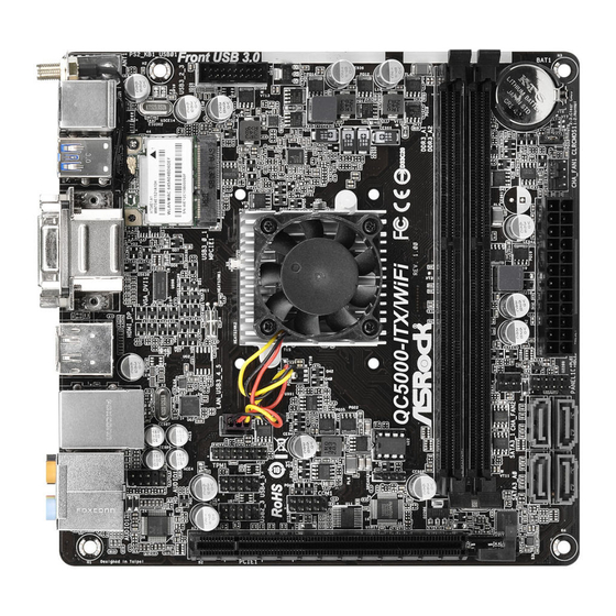
Page 14: Motherboard Layout
1.4 Motherboard Layout Front USB 3.0 CMOS USB3_2_3 Battery USB 2.0 T: USB0 B: USB1 CLRCMOS1 USB 3.0 CHA_FAN1 T: USB2 B: USB3 WiFi-802.11n Module PANEL 1 PLED PWRBTN CHA_FAN2 HDLED RESET USB 3.0 T: USB4 B: USB5 CPU_FAN1 32Mb TPMS1 BIOS HD_AUDIO1... - Page 15 Chassis Speaker Header (SPEAKER1) CPU Fan Connector (CPU_FAN1) COM Port Header (COM1) USB 2.0 Header (USB4_5) USB 2.0 Header (USB2_3) TPM Header (TPMS1) Front Panel Audio Header (HD_AUDIO1) * WiFi-802.11n Module and SMA Wi-Fi Antenna Cable are for QC5000-ITX/WiFi only.
-
Page 16: I/O Panel
1.5 I/O Panel No. Description No. Description USB 2.0 Ports (USB01) Microphone (Pink) D-Sub Port Optical SPDIF Out Port DisplayPort 1.2* USB 3.0 Ports (USB3_4_5) LAN RJ-45 Port** HDMI Port* Central / Bass (Orange) DVI-D Port Rear Speaker (Black) USB 3.0 Ports (USB3_0_1) Line In (Light Blue) PS/2 Mouse/Keyboard Port Antenna Por t (for QC5000-ITX /... - Page 17 QC5000-ITX/WiFi QC5000-ITX * HDMI and DisplayPort 1.2 cannot output at the same time. You can only choose either one of them. Please refer to the BIOS setup option “HDMI/DP Switch“ on page 40. ** There are two LEDs on each LAN port. Please refer to the table below for the LAN port LED indications.
-
Page 18: Wifi-802.11N Module And Asrock Wifi 2.4Ghz Antenna (For Qc5000-Itx/Wifi Only)
1.6 WiFi-802.11n Module and ASRock WiFi 2.4GHz Antenna (for QC5000-ITX/WiFi only) WiFi-802.11n Module WiFi-802.11n module is an easy-to-use wireless local area network (WLAN) adapter to support WiFi function. With WiFi-802.11n module, you can easily create a wireless environment and enjoy the convenience of wireless network connectivity. -
Page 19: Chapter 2 Installation
QC5000-ITX/WiFi QC5000-ITX Chapter 2 Installation This is a Mini-ITX form factor motherboard. Before you install the motherboard, study the configuration of your chassis to ensure that the motherboard fits into it. Pre-installation Precautions Take note of the following precautions before you install motherboard components or change any motherboard settings. -
Page 20: Installing Memory Modules (Dimm)
2.1 Installing Memory Modules (DIMM) This motherboard provides two 240-pin DDR3 (Double Data Rate 3) DIMM slots. It is not allowed to install a DDR or DDR2 memory module into a DDR3 slot; other- wise, this motherboard and DIMM may be damaged. The DIMM only fits in one correct orientation. - Page 21 QC5000-ITX/WiFi QC5000-ITX...
-
Page 22: Expansion Slots (Pci Express Slots)
2.2 Expansion Slots (PCI Express Slots) There are 2 PCI Express slots on the motherboard. Before installing an expansion card, please make sure that the power supply is switched off or the power cord is unplugged. Please read the documentation of the expansion card and make necessary hardware settings for the card before you start the installation. -
Page 23: Jumpers Setup
QC5000-ITX/WiFi QC5000-ITX 2.3 Jumpers Setup The illustration shows how jumpers are setup. When the jumper cap is placed on the pins, the jumper is “Short”. If no jumper cap is placed on the pins, the jumper is “Open”. The illustration shows a 3-pin jumper whose pin1 and pin2 are “Short”... -
Page 24: Onboard Headers And Connectors
2.4 Onboard Headers and Connectors Onboard headers and connectors are NOT jumpers. Do NOT place jumper caps over these headers and connectors. Placing jumper caps over the headers and connectors will cause permanent damage to the motherboard. System Panel Header Connect the power (9-pin PANEL1) switch, reset switch and... - Page 25 QC5000-ITX/WiFi QC5000-ITX Serial ATA3 Connectors These four SATA3 (SATA3_1: connectors support SATA see p.10, No. 8) data cables for internal (SATA3_2: storage devices with up to see p.10, No. 9) 6.0 Gb/s data transfer rate. (SATA3_A0: see p.10, No. 11) (SATA3_A1: see p.10, No.
-
Page 26: Atx Power Connector
1. High Definition Audio supports Jack Sensing, but the panel wire on the chassis must support HDA to function correctly. Please follow the instructions in our manual and chassis manual to install your system. 2. If you use an AC’97 audio panel, please install it to the front panel audio header by the steps below: A. - Page 27 QC5000-ITX/WiFi QC5000-ITX Serial Port Header This COM1 header (9-pin COM1) supports a serial port (see p.10, No. 14) module. TPM Header This connector supports (17-pin TPMS1) Trusted Platform Module (see p.10, No. 17) (TPM) system, which can securely store keys, digital certificates, passwords, and data.
-
Page 28: Chapter 3 Software And Utilities Operation
Chapter 3 Software and Utilities Operation 3.1 Installing Drivers The Support CD that comes with the motherboard contains necessary drivers and useful utilities that enhance the motherboard’s features. Running The Support CD To begin using the support CD, insert the CD into your CD-ROM drive. The CD automatically displays the Main Menu if “AUTORUN”... -
Page 29: A-Tuning
QC5000-ITX/WiFi QC5000-ITX 3.2 A-Tuning A-Tuning is ASRock’s multi purpose software suite with a new interface, more new features and improved utilities, including XFast RAM, Dehumidifier, Good Night LED, FAN-Tastic Tuning and a whole lot more. 3.2.1 Installing A-Tuning When you install the all-in-one driver to your system from ASRock’s support CD, A-Tuning will be auto-installed as well. - Page 30 Tools Various tools and utilities. XFast RAM Boost the system’s performance and extend the HDD’s or SDD’s lifespan! Create a hidden partition, then assign which files should be stored in the RAM drive. Fast Boot Fast Boot minimizes your computer's boot time. Please note that Ultra Fast mode is only supported by Windows 8 and the VBIOS must support UEFI GOP if you are using an external graphics card.
- Page 31 QC5000-ITX/WiFi QC5000-ITX Dehumidifier Prevent motherboard damages due to dampness. Enable this function and configure the period of time until the computer powers on, and the duration of the dehumidifying process. System Info View information about the system. Tech Service Contact Tech Service.
-
Page 32: Start8
3.3.1 Installing Start8 Install Start8, which is located in the folder at the following path of the Support CD: \ ASRock Utility > Start8. 3.3.2 Configuring Start8 Style Select between the Windows 7 style and Windows 8 style Start Menu. Then select... - Page 33 QC5000-ITX/WiFi QC5000-ITX Configure Configure provides configuration options, including icon sizes, which shortcuts you want Start Menu to display, quick access to recently used apps, the functionality of the power button, and more. Control...
- Page 34 Control lets you configure what a click on the start button or a press on the Windows key does. Desktop Desktop allows you to disable the hot corners when you are working on the desktop. It also lets you choose whether or not the system boots directly into desktop mode and bypass the Metro user interface.
-
Page 35: Chapter 4 Uefi Setup Utility
Chapter 4 UEFI SETUP UTILITY 4.1 Introduction ASRock Interactive UEFI is a blend of system configuration tools, cool sound effects and stunning visuals. Not only will it make BIOS setup less difficult but also a lot more amusing. This section explains how to use the UEFI SETUP UTILITY to configure your system. -
Page 36: Navigation Keys
4.1.2 Navigation Keys Use < > key or < > key to choose among the selections on the menu bar, and use < > key or < > key to move the cursor up or down to select items, then press <Enter>... -
Page 37: Main Screen
QC5000-ITX/WiFi QC5000-ITX 4.2 Main Screen When you enter the UEFI SETUP UTILITY, the Main screen will appear and display the system overview. QC-5000-ITX/WiFi Active Page on Entry Select the default page when entering the UEFI setup utility. QC-5000-ITX Active Page on Entry... -
Page 38: Oc Tweaker Screen
4.3 OC Tweaker Screen In the OC Tweaker screen, you can set up overclocking features. Because the UEFI software is constantly being updated, the following UEFI setup screens and descriptions are for reference purpose only, and they may not exactly match what you see on your screen. -
Page 39: Dram Timing Control
QC5000-ITX/WiFi QC5000-ITX DRAM Timing Control Power Down Enable Use this item to enable or disable DDR power down mode. Bank Interleaving Interleaving allows memory accesses to be spread out over banks on the same node, or accross nodes, decreasing access contention. -
Page 40: Voltage Configuration
Command Rate (CR) The delay between when a memory chip is selected and when the first active command can be issued. RAS# Cycle Time (tRC) Use this item to change RAS# Cycle Time (tRC) Auto/Manual setting. Write Recovery Time (tWR) The amount of delay that must elapse after the completion of a valid write operation, before an active bank can be precharged. -
Page 41: Advanced Screen
QC5000-ITX/WiFi QC5000-ITX 4.4 Advanced Screen In this section, you may set the configurations for the following items: CPU Con- figuration, Chipset Configuration, Storage Configuration, Super IO Configuration, ACPI Configuration, USB Configuration and Trusted Computing. Setting wrong values in this section may cause the system to malfunction. -
Page 42: Cpu Configuration
4.4.1 CPU Configuration Cool 'n' Quiet Use this item to enable or disable AMD’s Cool ‘n’ Quiet technology. The default value is [Enabled]. Configuration options: [Enabled] and [Disabled]. If you install ® Windows 8.1 / 8 / 7 / XP and want to enable this function, please set this item to [Enabled]. -
Page 43: Chipset Configuration
Enable/disable front panel HD audio. On/Off Play With ASRock On/Off Play users can connect their portable audio devices, such as an MP3 player or a mobile phone to the PC and listen to music through the computer's speakers even when the computer is turned off. -
Page 44: Onboard Lan
Standby/Hibernation mode. Spread Spectrum Enable Spread Spectrum to reduce electromagnetic interference for passing EMI tests. Mini PCIE WiFi Radio (for QC5000-ITX/WiFi only) Enable or disable the onboard WiFi Radio. HDMI/DP Switch Select to enable HDMI or DisplayPort. -
Page 45: Storage Configuration
QC5000-ITX/WiFi QC5000-ITX 4.4.3 Storage Configuration SATA Controller(s) Enable/disable the SATA controllers. SATA Mode Selection IDE: For better compatibility. AHCI: Supports new features that improve performance. AHCI (Advanced Host Controller Interface) supports NCQ and other new features that will improve SATA disk performance but IDE mode does not have these advan- tages. -
Page 46: Super Io Configuration
4.4.4 Super IO Configuration Serial Port Enable or disable the Serial port. Serial Port Address Select the address of the Serial port. -
Page 47: Acpi Configuration
QC5000-ITX/WiFi QC5000-ITX 4.4.5 ACPI Configuration Suspend to RAM It is recommended to select auto for ACPI S3 power saving. Check Ready Bit Enable to enter the operating system after S3 only when the hard disk is ready, this is recommended for better system stability. - Page 48 Ring-In Power On Allow the system to be waked up by onboard COM port modem Ring-In signals. RTC Alarm Power On Allow the system to be waked up by the real time clock alarm. Set it to By OS to let it be handled by your operating system.
-
Page 49: Usb Configuration
QC5000-ITX/WiFi QC5000-ITX 4.4.6 USB Configuration USB Controller Enable or disable all the USB ports. USB 3.0 Controller Enable or disable all the USB 3.0 ports. Legacy USB Support Enable or disable Legacy OS Support for USB 2.0 devices. If you encounter USB compatibility issues it is recommended to disable legacy USB support. -
Page 50: Trusted Computing
4.4.7 Trusted Computing Security Device Support Enable to activate Trusted Platform Module (TPM) security for your hard disk drives. -
Page 51: Tools
In order to prevent users from bypassing OMG, guest accounts without permission to modify the system time are required. UEFI Tech Service Contact ASRock Tech Service if you are having trouble with your PC. Please setup network configuration before using UEFI Tech Service. Easy Driver Installer For users that don’t have an optical disk drive to install the drivers from our support... -
Page 52: Network Configuration
Internet Flash ASRock Internet Flash downloads and updates the latest UEFI firmware version from our servers for you. Please setup network configuration before using Internet Flash. *For BIOS backup and recovery purpose, it is recommended to plug in your USB pen drive before using this function. - Page 53 QC5000-ITX/WiFi QC5000-ITX Dehumidifier Duration Configure the duration of the dehumidifying process before it returns to S4/S5 state. Dehumidifier CPU Fan Setting Configure the speed of the CPU fan while Dehumidifier is enabled. The higher the value, the faster the fan speed.
-
Page 54: Hardware Health Event Monitoring Screen
4.6 Hardware Health Event Monitoring Screen This section allows you to monitor the status of the hardware on your system, including the parameters of the CPU temperature, motherboard temperature, fan speed and voltage. CPU_FAN1 Setting Select a fan mode for CPU Fan 1, or choose Customize to set 5 CPU temperatures and assign a respective fan speed for each temperature. -
Page 55: Boot Screen
QC5000-ITX/WiFi QC5000-ITX 4.7 Boot Screen This section displays the available devices on your system for you to configure the boot settings and the boot priority. Fast Boot Fast Boot minimizes your computer's boot time. In fast mode you may not boot from an USB storage device. - Page 56 AddOn ROM Display Enable AddOn ROM Display to see the AddOn ROM messages or configure the AddOn ROM if you've enabled Full Screen Logo. Disable for faster boot speed. Boot Failure Guard If the computer fails to boot for a number of times the system automatically restores the default settings.
- Page 57 QC5000-ITX/WiFi QC5000-ITX Launch PXE OpROM Policy Select UEFI only to run those that support UEFI option ROM only. Select Legacy only to run those that support legacy option ROM only. Do not launch? Launch Storage OpROM Policy Select UEFI only to run those that support UEFI option ROM only. Select Legacy only to run those that support legacy option ROM only.
-
Page 58: Security Screen
4.8 Security Screen In this section you may set or change the supervisor/user password for the system. You may also clear the user password. Supervisor Password Set or change the password for the administrator account. Only the administrator has authority to change the settings in the UEFI Setup Utility. Leave it blank and press enter to remove the password. -
Page 59: Exit Screen
QC5000-ITX/WiFi QC5000-ITX 4.9 Exit Screen Save Changes and Exit When you select this option the following message, “Save configuration changes and exit setup?” will pop out. Select [OK] to save changes and exit the UEFI SETUP UTILITY. Discard Changes and Exit When you select this option the following message, “Discard changes and exit... -
Page 60: Contact Information
Contact Information If you need to contact ASRock or want to know more about ASRock, you’re welcome to visit ASRock’s website at http://www.asrock.com; or you may contact your dealer for further information. For technical questions, please submit a support request form at http://www.asrock.com/support/tsd.asp...