
Related Manuals for Capital PSGR244


Summary of Contents for Capital PSGR244
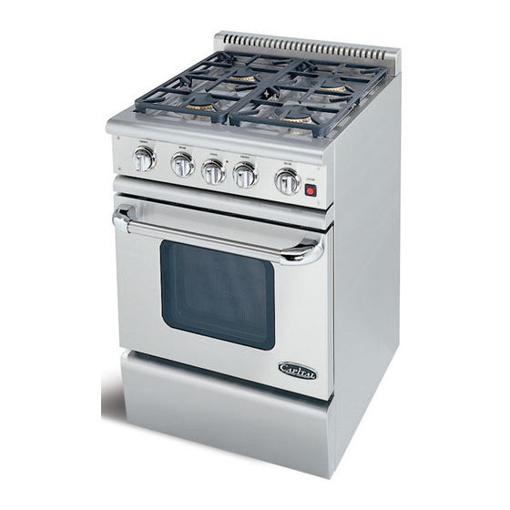
- Page 1 I N S T A L L A T I O N G U I D E P E R F O R M A N C E S E R I E S ™ G A S R A N G E S THE POWER OF PERFORMANCE™...
-
Page 2: Table Of Contents
contents message important safety warnings ii-iii contents important installation instructions STEP 1 unpacking, moving, and placing the range STEP 2 ventilation requirements STEP 3 3a cabinet preparation cabinet clearances 3b backguard installation 3c electrical supply STEP 4 installing anti-tip device STEP 5 gas connection and hookup testing and adjustments... - Page 3 We realize you have a choice in your appliance needs so we feel honored to welcome you to our family, where passion for improving the quality of your culinary life is our number one priority. your friends at Capital Cooking Equipment.
- Page 4 warnings WARNING! If the information in this manual is not followed EXACTLY, a fire or explosion resuly, causing property damage, personal injury or death. IMPORTANT: Save these instructions for the Local Gas Inspector’s use. * DO NOT store or use gasoline or other INSTALLER: flammable vapors and liquids in the vicinity Please leave these Installation Instructions with the...
-
Page 5: Contents
warnings CAUTION! When connecting the unit to propane gas, make certain the propane tank is equipped with its own high-pressure regulator in addition to the pressure regulator supplied with the range. The pressure of the gas supplied to the appliance must not exceed 14” (34.57 mB) water column from the propane gas tank to the pressure regulator. -
Page 6: Important Installation Instructions
INTRODUCTION: Capital’s Performance Series™ Gas Ranges are tested and approved in accordance with ANSI Z21.1b-2003/CGA IR 58, 1995, Household Cooking Appliances. It is STRONGLY RECOMMENDED that this appliance be installed in conjunction with a suitable overhead VENT HOOD. Due to the high heat output of this unit, particular attention should be paid to the hood and ductwork installation to assure it meets local building codes. -
Page 7: Unpacking, Moving, And Placing The Range
step 1: unpacking, moving and placing the range 1) Remove the outer carton and packing CAUTION! materials from the shipping base. The all gas Proper equipment and adequate manpower ranges are held to the skid by four (4) bolts. must be used in moving the range to avoid After removing the bolts the range must be damage to the unit or the floor. -
Page 8: Ventilation Requirements
Where space permits, a hood larger in width than the cooking surface may be desirable for improved ventilation performance. NOTE: Capital Cooking does not manufacture an island VENT HOOD BLOWER CFMS style ventilation hood. A wall mount hood is not suitable for island type installations. -
Page 9: Step
Low Back or High Shelf back guard must be installed (see Fig. 2). When clearance to combustible WARNING! material D is over 12”, a Capital Island Trim may DO NOT obstruct the flow of combustion and be used. Figure 2 indicates the space required ventilation air to the unit. -
Page 10: Cabinet Clearances
step 3a: cabinet preparation (cont.) Fig. 2 Combustible Materials 12" Min. to Combustibles without backguard 40" Min. to Combustibles 10-3/4" HIGH SHELF 22" LOW BACK 12" ISLAND TRIM wall O" Clearance KICKPLATE MODEL # WIDTH PSGR24 23-7/8" 25" 43-1/4" 27-3/8" 38-5/8"... -
Page 11: 3B Backguard Installation
step 3b: backguard installation Fig. 2Ab 1. Remove the rang e back panel by removing the 6 screws -- 3 screws on each side (see Pics. A and B). 2. Remove, then discard the 4 screws (2 at each side at the top of range side trim). Pic. -
Page 12: 3C Electrical Supply
step 3c: electrical supply Installation of All Gas ranges must be planned so that the rough-in of the junction box for the receptacle or conduit connection allows for maximum clearance to the rear of the unit. This is especially critical if the junction box in the wall will be directly behind the junction box of the unit when the unit is installed. -
Page 13: Installing Anti-Tip Device
step 4: installing anti-tip device NOTE: READ THESE IMPORTANT The anti-tip device supplied with each range SAFETY WARNINGS! MUST be installed per these instruictions! failure to do so WILL void warranty. WARNING! • All ranges can tip • Injury to persons and property could result •... - Page 14 step 4: installing anti-tip device (cont.) IMPORTANT INSTALLATION INFORMATION: 1) The Anti-Tip Bracket may be attached to a solid wood cabinet having a minimum wall thickness of 3/4”. 2) The thickness of the wall or floor may require use of longer screws, available at your local hardware store.
-
Page 15: Gas Connection And Hookup
NOTE: codes or ordinances. In the absence of local codes or Capital DOES NOT supply ranges to match varying ordinances, please refer to National Fuel Gas Code altitudes. Orifices to adjust for combustion for differing ANSI Z223.1 / NFPA54-Current Issue. - Page 16 step 5: gas connection and hook-up (cont.) CAUTION! The appliance must be isolated from the gas supply piping system by closing its individual manual shut-off valve during any pressure testing of the gas supply piping system at test pressures equal to or less than 1/2 psig (3.5kPa.). The Appliance and its individual shut off valve must be disconnected from the gas supply piping system during any pressure testing of the system...
-
Page 17: Testing And Adjustments
testing and adjustments (cont.) NOTE: If the sealed burners do not ignite and there is NO clicking sound, turn OFF the gas and check for tripped circuit breakers, blown fuse or wire connection to the igniter. Fig. 8 cleaning stainless steel The stainless steel surfaces may be cleaned by wiping with a damp soapy cloth, rinsing with clear water and drying with a soft cloth to avoid water marks. -
Page 18: Installer Checklist
final checklist installer, please initial beside each item GENERAL: OPERATION: c Placement of unit c All internal packing materials removed. Check c Specified clearances maintained to cabinet below grates and grill pans and within ovens surfaces c If used on propane gas, verify that the propane c Unit level--front to back-- side to side gas supply is equipped with its own high- c Burner caps positioned properly on sealed... -
Page 19: We're Here For You
Capital Cooking Equipment Attn: Customer Service 13211 Florence Ave Santa Fe Springs, CA 90670 Fax us at: 562-903-1167 For service email us at: customerservice@capital-cooking.com For parts email us at: parts@capital-cooking.com... -
Page 20: Warranty
Capital to be defective. Replacement will be FOB Capital, and Capital will not be liable for any transportation costs, labor costs, or export duties. This warranty shall not apply, nor can we assume responsibility for damage that might result from a failure to follow manufacturer’s instructions or local codes, where the appliance has been tampered with or altered in any way... - Page 21 Capital Cooking Equipment dealer or visit us online at www.capital-cooking.com. © 2006 Capital Cooking Equipment, Inc. Not to be reproduced wholly or in part without written permission from Capital Cooking Equipment, Inc. Capital Cooking Equipment, Inc.