HP TouchSmart 9300 Elite Maintenance & Service Manual
All-in-one business pc
Hide thumbs
Also See for TouchSmart 9300 Elite:
- Hardware reference manual (45 pages) ,
- Quickspecs (13 pages)
Table of Contents
Advertisement
Advertisement
Table of Contents

Related Manuals for HP TouchSmart 9300 Elite


Summary of Contents for HP TouchSmart 9300 Elite
- Page 1 Maintenance & Service Guide HP TouchSmart 9300 Elite All-in-One Business...
- Page 2 Microsoft and Windows are trademarks of Microsoft Corporation in the U.S. and other countries. The only warranties for HP products and services are set forth in the express warranty statements accompanying such products and services. Nothing herein should be construed as constituting an additional warranty.
-
Page 3: About This Book
About This Book WARNING! Text set off in this manner indicates that failure to follow directions could result in bodily harm or loss of life. CAUTION: Text set off in this manner indicates that failure to follow directions could result in damage to equipment or loss of information. - Page 4 About This Book...
-
Page 5: Table Of Contents
Table of contents 1 Product Features ............................1 Front Components ..........................3 Side Components ..........................4 Rear Components ..........................5 2 Installing and Customizing the Software ...................... 6 Installing the Operating System ......................6 Downloading Microsoft Windows Updates ................... 6 Installing or Upgrading Device Drivers (Windows systems) .............. - Page 6 Generating Static ....................... 20 Preventing Electrostatic Damage to Equipment ..............20 Personal Grounding Methods and Equipment ..............21 Grounding the Work Area ....................21 Recommended Materials and Equipment ................21 Operating Guidelines .......................... 22 Routine Care ............................23 General Cleaning Safety Precautions ................23 Cleaning the Computer Case ....................
- Page 7 Volume button board .......................... 69 Rear logo cover ..........................71 Webcam module ..........................72 Main rear frame ..........................74 Power button board ..........................75 System board shield ........................... 76 Speakers ............................78 Infrared sensor board ......................... 80 Fan ..............................82 Fan Sink (Thermal Module) ........................
- Page 8 Contacting Customer Support ......................148 Appendix C Connector Pin Assignments ....................149 Ethernet BNC ........................... 149 USB ..............................149 Microphone ............................149 Headphone ............................150 Line-in Audio ............................ 150 Line-out Audio ..........................150 Appendix D Power Cord Set Requirements ....................151 General Requirements ........................
-
Page 9: Product Features
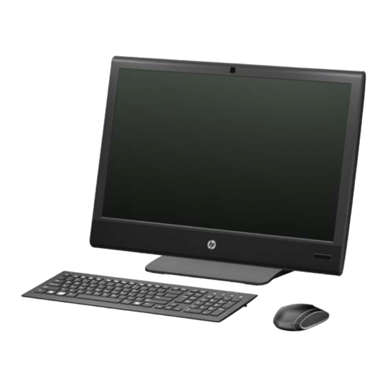
Figure 1-1 HP TouchSmart 9300 Elite Business PC NOTE: The wireless keyboard and mouse shown above are optional accessories. The HP TouchSmart 9300 Elite Business PC offers the following features: ● Integrated All-in-One form factor ● 23-inch diagonal widescreen WLED backlit BrightView LCD ●... - Page 10 Removable panels on the back of the chassis allow administrators to easily and efficiently service the PC ● HP TouchSmart software suite for instant access to calendar, Internet, notes, and multimedia content ● ENERGY STAR® qualified, EPEAT® Gold registered, and offers 90-percent energy-efficient power ●...
-
Page 11: Front Components
Front Components Figure 1-2 Front Components Table 1-1 Front Components Component Component 58.4 cm (23-inch) diagonal, 16:9 widescreen, touch- Dual wireless antenna enabled, full HD, white LED backlit LCD display Dual microphone array (optional) High-performance stereo speakers Webcam (optional) IR Receiver (select models only) Front Components... -
Page 12: Side Components
Side Components Figure 1-3 Side Components Table 1-2 Side Components Component Component Volume up button Microphone/line in jack Volume down button Headphone jack Mute button Slot-load optical drive (optional) Hard drive activity LED Optical drive eject button Media card reader activity LED Optical drive activity LED Media card reader Power LED... -
Page 13: Rear Components
Rear Components Figure 1-4 Rear Components Table 1-3 Rear Components Component Component Drive access panel Power indicator light Webcam adjustment wheel Rear port security cover Memory access panel TV coax in (optional) Adjustable reclining stand IR Emitter (Blaster) output (optional) Security lock slot (4) USB 2.0 ports Power connector release latch... -
Page 14: Installing And Customizing The Software
If the computer was shipped with Windows Vista or Windows 7 loaded, you will be prompted to register the computer with HP Total Care before installing the operating system. You will see a brief movie followed by an online registration form. Fill out the form, click the Begin button, and follow the instructions on the screen. -
Page 15: Installing Or Upgrading Device Drivers (Windows Systems)
Obtain the latest support software, including support software for the operating system from http://www.hp.com/support. Select your country and language, select Download drivers and software (and firmware), enter the model number of the computer, and press Enter. Protecting the Software To protect the software from loss or damage, keep a backup copy of all system software, applications, and related files stored on the hard drive. -
Page 16: Computer Setup (F10) Utility
Computer Setup (F10) Utility Computer Setup (F10) Utilities Use Computer Setup (F10) Utility to do the following: ● Change factory default settings. ● Set the system date and time. ● Set, view, change, or verify the system configuration, including settings for processor, graphics, memory, audio, storage, communications, and input devices. -
Page 17: Using Computer Setup (F10) Utilities
● Solve system configuration errors detected but not automatically fixed during the Power-On Self- Test (POST). ● Replicate the system setup by saving system configuration information on a USB flash drive and restoring it on one or more computers. ● Execute self-tests on a specified ATA hard drive (when supported by drive). -
Page 18: Computer Setup-File
Computer Setup—File NOTE: Support for specific Computer Setup options may vary depending on the hardware configuration. Table 3-2 Computer Setup—File Option Description System Information Lists: ● Product name ● SKU number (some models) ● Processor type/speed/stepping ● Cache size (L1/L2/L3) ●... -
Page 19: Computer Setup-Storage
Computer Setup—Storage NOTE: Support for specific Computer Setup options may vary depending on the hardware configuration. Table 3-3 Computer Setup—Storage Option Description Device Configuration Lists all installed BIOS-controlled storage devices. When a device is selected, detailed information and options are displayed. The following options may be presented: Hard Disk: Size, model, firmware, serial number, emulation type. -
Page 20: Computer Setup-Security
Computer Setup—Security NOTE: Support for specific Computer Setup options may vary depending on the hardware configuration. Table 3-4 Computer Setup—Security Option Description Setup Password Allows you to set and enable a setup (administrator) password. NOTE: If the setup password is set, it is required to change Computer Setup options, flash the ROM, and make changes to certain plug and play settings under Windows. - Page 21 Table 3-4 Computer Setup—Security (continued) ◦ USB Port 11 ◦ USB Port 13 Slot Security Allows you to disable or enable any Mini Card slot Network Boot Enables/disables the computer’s ability to boot from an operating system installed on a network server.
- Page 22 Table 3-4 Computer Setup—Security (continued) System Security Data Execution Prevention (some models) (enable/disable) - Helps prevent operating system (some models: these security breaches. options are hardware PAVP (Models with Blu-ray drives) (disabled/min/max) - PAVP enables the Protected Audio Video dependent) Path in the Chipset.
-
Page 23: Computer Setup-Power
Computer Setup—Power NOTE: Support for specific Computer Setup options may vary depending on the hardware configuration. Table 3-5 Computer Setup—Power Option Description ● Hardware Power SATA Power Management—Enables or disables the SATA bus and/or device power Management management. Default is enabled. ●... -
Page 24: Computer Setup-Advanced
Computer Setup—Advanced NOTE: Support for specific Computer Setup options may vary depending on the hardware configuration. Table 3-6 Computer Setup—Advanced Option Heading Power-On Options Allows you to set: ● POST messages (enable/disable). Suppresses most POST messages, such as memory count, product name, and other non-error text messages. If a POST error occurs, the error is displayed regardless of the mode selected. -
Page 25: Serial Ata (Sata) Drive Guidelines And Features
3.0 Gb/s SATA Hard Drive Cables SATA Data Cable Always use an HP approved SATA 3.0 Gb/s cable as it is fully backwards compatible with the SATA 1.5 Gb/s drives. Current HP desktop products ship with SATA 3.0 Gb/s hard drives. -
Page 26: Smart Ata Drives
SMART ATA Drives The Self Monitoring Analysis and Recording Technology (SMART) ATA drives for the HP Personal Computers have built-in drive failure prediction that warns the user or network administrator of an impending failure or crash of the hard drive. The SMART drive tracks fault prediction and failure indication parameters such as reallocated sector count, spin retry count, and calibration retry count. -
Page 27: Identifying The Chassis, Routine Care, And Disassembly Preparation
Identifying the Chassis, Routine Care, and Disassembly Preparation This chapter provides general service information for the computer. Adherence to the procedures and precautions described in this chapter is essential for proper service. CAUTION: When the computer is plugged into an AC power source, voltage is always applied to the system board. -
Page 28: Electrostatic Discharge Information
Electrostatic Discharge Information A sudden discharge of static electricity from your finger or other conductor can destroy static-sensitive devices or microcircuitry. Often the spark is neither felt nor heard, but damage occurs. An electronic device exposed to electrostatic discharge (ESD) may not appear to be affected at all and can work perfectly throughout a normal cycle. -
Page 29: Personal Grounding Methods And Equipment
● Always be properly grounded when touching a sensitive component or assembly. ● Avoid contact with pins, leads, or circuitry. ● Place reusable electrostatic-sensitive parts from assemblies in protective packaging or conductive foam. Personal Grounding Methods and Equipment Use the following equipment to prevent static electricity damage to equipment: ●... -
Page 30: Operating Guidelines
● Conductive bins and other assembly or soldering aids ● Conductive foam ● Conductive tabletop workstations with ground cord of one-megohm +/- 10% resistance ● Static-dissipative table or floor mats with hard tie to ground ● Field service kits ● Static awareness labels ●... -
Page 31: Routine Care
Routine Care General Cleaning Safety Precautions Never use solvents or flammable solutions to clean the computer. Never immerse any parts in water or cleaning solutions; apply any liquids to a clean cloth and then use the cloth on the component. Always unplug the computer when cleaning with liquids or damp cloths. -
Page 32: Cleaning The Monitor
If an incorrect screw is used during the reassembly process, it can damage the unit. HP strongly recommends that all screws removed during disassembly be kept with the part that was removed, then returned to their proper locations. -
Page 33: Cables And Connectors
Batteries, battery packs, and accumulators should not be disposed of together with the general household waste. In order to forward them to recycling or proper disposal, please use the public collection system or return them to HP, their authorized partners, or their agents. Service Considerations... -
Page 34: Illustrated Parts Catalog
Description Spare part number System board 658978-001 652321-001 Optical drive (does not include bezel) HP SuperMulti DVD Writer Drive 583092-001 HP Slim Slot Blu-ray Combo Drive 583093-001 Left side cap, no optical drive 658989-001 Speakers Right speaker 652274-001 Left speaker... - Page 35 Item Description Spare part number Fan sink assembly (thermal module) (includes replacement thermal material) Discrete graphics 658987-001 UMA graphics 658988-001 Memory modules (PC3-10600, 1333-MHz; not illustrated) 4-GB 646801-001 2-GB 646800-001 Processor (includes replacement thermal material; not illustrated) Intel Core i7 processors 2600 (3.4-GHz, 8-MB L3 cache) 638632-001 Intel Core i5 processors...
- Page 36 Item Description Spare part number ● Brazil 590271-201 ● French Canada 590271-121 ● Latin America 590271-161 ● The United States 590271-001 USB Enterprise ● Brazil 658990-201 ● French Canada 658990-121 ● Latin America 658990-161 ● The United States 658990-001 Wireless for use in the United States 611376-003 USB Smartcard ●...
-
Page 37: Boards
628380-001 Infrared sensor board 652307-001 WLAN modules Intel Centrino® Advanced-N 6205 802.11a/b/g/n 652165-001 802.11b/g/n 654602-001 HP WLAN combo 802.11b/g/n + Bluetooth 2.1 card 652279-001 Volume button board 652306-001 G-sensor board (not illustrated) 658983-001 TV tuner module (not illustrated) 613990-001 Boards... -
Page 38: Cables
Spare part Description number 583092-001 HP SuperMulti DVD Writer Drive 583093-001 HP Slim Slot Blu-ray Combo Drive 590271-001 USB keyboard for use in the United States 590271-121 USB keyboard for use in French Canada 590271-161 USB keyboard for use in Latin America... - Page 39 Speaker, right 652275-001 Speaker, left 652276-001 IR blaster cable 652277-001 Webcam module without DMIC 652279-001 HP WLAN combo 802.11b/g/n + Bluetooth 2.1 card 652286-001 Optical drive transfer cable, 275 mm 652299-001 Optical drive eject cable, 190 mm 652305-001 Power board 652306-001...
- Page 40 Spare part Description number 652307-001 Infrared sensor board 652311-001 Optical drive connector board 652312-001 Optical drive eject board 652321-001 654301-001 Sensor2 cable, 100 mm 654598-001 Webcam lens cover 654599-001 AC adapter, 180W (external) 654600-001 230-W AC adapter 654601-001 Intel Core i5, 2300 processor (2.8-GHz, 6-MB L3 cache) 654602-001 802.11b/g/n WLAN card 655971-001...
-
Page 41: Removal And Replacement Procedures
Disconnect all cables from the ports. Place the computer face down on a soft flat surface. HP recommends that you set down a blanket, towel, or other soft cloth to protect the screen surface from scratches or other damage. -
Page 42: Stand
Stand The stand is secured with four screws. The screws are covered by the plastic piece covering the back of the stand. To remove the stand: Prepare the computer for disassembly (see Preparing to disassemble the computer on page 33). Insert your finger, or a flathead screwdriver, into the slot on the stand cover (1) to pry it off of the computer stand. - Page 43 Remove the four Torx screws (1), slide the stand toward the top of the computer, and then lift the stand off the computer (2). NOTE: You can use a Torx or a flat-head driver to remove the screws. Figure 7-2 Removing the stand To replace the stand, reverse the removal procedures.
-
Page 44: Vesa Mount
VESA mount The VESA adapter plate is stored in the bottom of the stand and is mounted in place of the stand. To install the VESA adapter plate: Prepare the computer for disassembly (see Preparing to disassemble the computer on page 33). - Page 45 Use a Phillips screwdriver to tighten the recessed two brake screws (for the rails) on the computer. It should take about 5–10 turns of the screwdriver to secure the screws. Take care not to overtighten the screws. NOTE: The tightened brake screws will hold the VESA adapter plate in the locked position, so that the computer does not slide down once it is mounted on a wall.
- Page 46 While the stand is still on the computer, use a Phillips screwdriver to remove the four screws attaching the VESA adapter plate to the bottom of the computer stand. Save the screws. Figure 7-5 Removing the VESA adapter screws Remove the VESA adapter plate from the bottom of the computer stand. Figure 7-6 Removing the VESA adapter plate Chapter 7 Removal and Replacement Procedures...
- Page 47 Use a flathead screwdriver to remove the four screws attaching the computer stand to the back of the computer. Figure 7-7 Removing the stand screws VESA mount...
- Page 48 Lift the computer stand away from the computer. Figure 7-8 Removing the stand Chapter 7 Removal and Replacement Procedures...
- Page 49 Place the VESA adapter plate over the rails on the back of the computer, matching the cutouts on the each side of the plate with the screw holes and the hooks on the rails. Figure 7-9 Placing the VESA adapter plate on the computer VESA mount...
- Page 50 Attach the VESA adapter plate to the back of the computer, using a Phillips screwdriver to tighten the four screws. Figure 7-10 Securing the VESA adapter plate Chapter 7 Removal and Replacement Procedures...
- Page 51 Slide the VESA adapter plate upward until it locks into place. You will hear a click when the VESA adapter plate is locked in place. NOTE: If you do not hear the click or the plate does not lock in place, it means the two brake screws were not sufficiently tightened when the computer stand was removed.
- Page 52 Attach the wall-mounting hardware (purchased separately) to the VESA adapter plate, according to the manufacturer's instructions, using either the 100 mm x 100 mm screw holes or the 100 mm x 200 mm screw holes. Figure 7-12 100 mm x 100 mm holes Figure 7-13 100 mm x 200 mm holes NOTE:...
- Page 53 NOTE: If the computer stand is ever replaced on the computer, the VESA adapter plate must be replaced on the bottom of the computer stand in order to properly support the computer. Note the following information about the computer without the stand but with the VESA adapter installed.
-
Page 54: Rear Panels
Rear panels The rear panels are located above the stand. You must remove them to access internal components. Although the following procedure shows only removing one panel, the procedure is the same for both panels. To remove the rear panels: Prepare the computer for disassembly (see Preparing to disassemble the computer on page 33). - Page 55 Before removing the rear panel, you must remove the small cover plate that hides the screw used to secure the panel to the chassis. Lift up on the bottom of the cover plate located next to the upper inside corner of the rear panel and lift the cover plate off the rear of the computer. Figure 7-16 Removing the rear panel screw cover plate Remove the screw beneath the cover plate (1) and slide the rear panel toward the center of the...
- Page 56 Lift up the outside edge of the panel approximately 2.5 cm (1 inch) (1) and slide the panel toward the outside edge of the computer (2) to remove it. Figure 7-18 Removing the rear panel To replace the rear panels, reverse the removal procedures. NOTE: When replacing a drive access panel, hold the panel at a slight angle with the inside edge of the panel lower than the outside edge, then slide the screw hole tab on the top inside corner of the...
-
Page 57: Installing Memory
Installing memory Description Spare part number 4-GB 646801-001 2-GB 646800-001 The memory modules are located under the rear cover on the right side of the computer (when viewed from behind). Figure 7-20 Memory location The computer comes with double data rate 3 synchronous dynamic random access memory (DDR3- SDRAM) small outline dual inline memory modules (SODIMMs). -
Page 58: Populating Sodimm Sockets
In addition, the computer supports: ● 512-Mbit, 1-Gbit, and 2-Gbit non-ECC memory technologies ● single-sided and double-sided SODIMMs ● SODIMMs constructed with x8 and x16 devices; SODIMMs constructed with x4 SDRAM are not supported NOTE: The system will not operate properly if you install unsupported SODIMMs. Populating SODIMM sockets The memory sockets on the system board can be populated with up to four industry-standard SODIMMs. -
Page 59: Installing Sodimms
The system will automatically operate in single channel mode, dual channel mode, or flex mode, depending on how the SODIMMs are installed. ● The system will operate in single channel mode if the SODIMM sockets are populated in one channel only. ●... - Page 60 To remove a SODIMM, press outward on the two latches on each side of the SODIMM (1) then pull the SODIMM out of the socket (2). Figure 7-22 Removing a memory module To install a SODIMM, slide the new SODIMM into the socket at approximately a 30° angle (1) then press the SODIMM down (2) so that the latches lock it in place.
-
Page 61: Hard Drive
Hard drive Description Spare part number 1000-GB 636930-001 750-GB 639363-001 500-GB 636939-001 320-GB 634824-001 250-GB 636927-001 160-GB solid-state drive 646809-001 80-GB solid-state drive 607817-001 The hard drive is located under the rear panel on the left side of the computer (when viewed from behind). - Page 62 Loosen the captive screw on the side of the hard drive cage that secures the cage to the computer. Figure 7-25 Loosening the hard drive cage screw Grasp the handle on top of the hard drive cage and slide the cage toward the outer edge of the computer, then lift the cage out of the computer.
- Page 63 To remove the hard drive from the hard drive cage, remove the four screws on the sides of the cage that secure the drive to the cage (1), and then slide the drive out of the cage (2). Figure 7-27 Removing the hard drive from the cage Reconnect and reconfigure the computer.
-
Page 64: Inverter Board
Inverter board Description Spare part number Inverter board 658982-001 The inverter board is located on the left side of the computer on top of the optical drive cage. It is secured with two screws and has two connectors. Figure 7-28 Inverter board location To remove the inverter board: Prepare the computer for disassembly (see... - Page 65 Remove the inverter board from the computer (3). Figure 7-29 Removing the Inverter board To install the inverter board, reverse the removal procedures. Inverter board...
-
Page 66: Optical Drive Connector Board
Optical drive connector board Description Spare part number Optical drive connector board 652311-001 Optical drive transfer cable, 275 mm 652286-001 The optical drive connector board is located on the left side of the computer (when viewed from behind). It is secured by two screws and has two connectors – one to the system board, one to the optical drive eject board. - Page 67 Pull the board away from the optical drive bracket, and then remove it from the computer (3). Figure 7-31 Removing the optical drive connector board Remove the board from the computer. To install the optical drive connector board, reverse the removal procedures. Optical drive connector board...
-
Page 68: Left Cap
Left cap Description Spare part number Left side cap, no optical drive 658989-001 The left cap is located on the left side of the computer. You must remove it to remove the optical drive, optical drive eject board, rear logo cover, and main rear frame. Figure 7-32 Left cap location To remove the left cap:... - Page 69 Rotate the cap to disengage it from the computer (2), and then remove it (3). Figure 7-33 Removing the left side cap To install an left cap, reverse the removal procedures. Left cap...
-
Page 70: Optical Drive
Spare part number HP SuperMulti DVD Writer Drive 583092-001 HP Slim Slot Blu-ray Combo Drive 583093-001 The optical drive is located under the drive cover on the left side of the computer (when viewed from behind). It is secured with one screw. You must remove the left side cap to remove the optical drive. - Page 71 Loosen the captive screw (1) that secures the drive to the computer, and then push on the drive bracket (2) to slide the drive out of the computer (3). Figure 7-35 Removing the optical drive If you need to remove the drive bracket from the drive, remove the two screws (1) that secure the bracket to the drive, and then remove the bracket from the drive (2).
-
Page 72: Optical Drive Eject Board
Optical drive eject board Description Spare part number Optical drive eject board 652312-001 Optical drive eject cable, 190 mm 652299-001 The optical drive eject board is located under the left side cap. It is secured with one screw and has one connector. - Page 73 From the outside of the computer, remove the screw that secures the board to the computer. Figure 7-38 Removing the optical drive eject board screw From the inside of the computer, disconnect the cable from the board. NOTE: Be careful not to damage the cable when disconnecting it from the connector. Do not pull on the wires.
-
Page 74: Right Cap
Right cap The right cap is located along the right side of the computer (when viewed from behind). It is secured with two screws, and it houses the volume board. You do not have to remove the volume board when removing the cap if you disconnect the volume board cable from the system board. - Page 75 Rotate the cap to disengage it from the computer (2), and then remove it far enough to gain access to the volume board cable connector (3). Figure 7-41 Removing the right cap Right cap...
- Page 76 Disconnect the volume board cable from the system board. Figure 7-42 Disconnecting the volume board cable Remove the cap from the computer. To install the right cap, reverse the removal procedures. Chapter 7 Removal and Replacement Procedures...
-
Page 77: Volume Button Board
Volume button board Description Spare part number Volume button board 652306-001 The volume button board is located in the right side cap. It is secured with two screws and has one connector. Figure 7-43 Volume button board location To remove the volume board: Prepare the computer for disassembly (see Preparing to disassemble the computer on page 33). - Page 78 Lift the board from the cap (2). Figure 7-44 Removing the volume button board To install the volume button board, reverse the removal procedures. Chapter 7 Removal and Replacement Procedures...
-
Page 79: Rear Logo Cover
Remove the 4 screws that secure the cover to the computer. Pry the cover up to disengage it from the computer, and then pull it toward the top and off the computer. You may experience significant resistance under the HP logo. Figure 7-45 Removing the rear logo cover To replace the rear logo cover, reverse the removal procedures. -
Page 80: Webcam Module
Webcam module Description Spare part number Webcam module without DMIC 652277-001 Webcam module, 2.0 MP, FHD 658985-001 Webcam lens cover 654598-001 Webcam wheel cap 658986-001 The webcam module is located at the top of the computer. It is secured with two screws and has one connector. - Page 81 Remove the module from the computer (3). Figure 7-47 Removing the webcam module To install a webcam module, reverse the removal procedures. Webcam module...
-
Page 82: Main Rear Frame
Main rear frame The main rear frame is secured with 15 screws. To remove it, you must first remove the rear logo cover, which is held on with four screws. To remove the main rear frame: Prepare the computer for disassembly (see Preparing to disassemble the computer on page 33). -
Page 83: Power Button Board
Power button board Description Spare part number Power button board 652305-001 The power button board is located under the left side cap near the bottom of the computer. It is secured with one screw and has one connector. Figure 7-49 Power button board location To remove the power button board: Prepare the computer for disassembly (see... -
Page 84: System Board Shield
Disconnect the cable from the board (2), and then remove the board from the computer. NOTE: Be careful not to damage the cable when disconnecting it from the connector. Do not pull on the wires. Figure 7-50 Removing the power button board To install the power button board, reverse the removal procedures. - Page 85 Lift the left side of the shield first (3), and then pull the shield up and off the system board. Figure 7-51 Removing the system board shield To install the system board shield, reverse the removal procedures. When replacing the shield, make sure to place the five tabs on the right side of the shield into their slots in the computer before placing the shield atop the system board.
-
Page 86: Speakers
Speakers Description Spare part number Right speaker 652274-001 Left speaker 652275-001 The speakers are located at the bottom of the computer. Two separate speakers are each secured by two screws. Figure 7-53 Speaker location To remove the speakers: Prepare the computer for disassembly (see Preparing to disassemble the computer on page 33). - Page 87 Lift the speakers straight up and out of the computer (3). Figure 7-54 Removing the speakers Figure 7-55 Removing the speakers To install the speakers, reverse the removal procedures. Speakers...
-
Page 88: Infrared Sensor Board
Infrared sensor board Description Spare part number Infrared sensor board 652307-001 The infrared board is located on the bottom left side of the computer, under the left speaker. It is secured with one screw and has one connector. Figure 7-56 Infrared board location To remove the infrared board: Prepare the computer for disassembly (see... - Page 89 Lift the board from the computer (3). Figure 7-57 Removing the infrared board To install the infrared board, reverse the removal procedures. Infrared sensor board...
-
Page 90: Fan
Description Spare part number 652321-001 The fan is located near the top of the computer. It is secured with three screws. You do not have to remove the heat sink to remove it. Figure 7-58 Fan location To remove the fan: Prepare the computer for disassembly (see Preparing to disassemble the computer on page 33). - Page 91 Lift the fan from the computer (3). Figure 7-59 Removing the fan To install the fan, reverse the removal procedures.
-
Page 92: Fan Sink (Thermal Module)
Fan Sink (Thermal Module) Description Spare part number Fan sink (thermal module) for use in computers with discrete graphics 658987-001 Fan sink (thermal module) for use in computers with UMA graphics 658988-001 The fan sink is secured with four screws. You do not have to remove the chassis fan to remove the it. Figure 7-60 Fan location To remove the fan sink:... -
Page 93: Processor
Slide the fan sink toward the top of the computer (3), and then lift it off the system board . Figure 7-61 Removing the fan sink To replace the fan sink, reverse the removal procedures. Processor Description Spare part number Intel Core i7 processor 2600 (3.4-GHz, 8-MB L3 cache) 638632-001... - Page 94 To remove the processor: Prepare the computer for disassembly (see Preparing to disassemble the computer on page 33). Remove the stand (see Stand on page 34). Remove the right and left rear panels (see Rear panels on page 46). Remove the left cap (see Left cap on page 60).
- Page 95 To install a new processor: Place the processor in its socket and close the retainer. Secure the locking lever. If reusing the existing heat sink, go to step 3. If using a new heat sink, go to step 5. If reusing the existing heat sink, clean the bottom of the heat sink with the alcohol pad provided in the spares kit.
-
Page 96: Hard Drive Connector
Hard drive connector The hard drive connector is located near the middle of the computer. You must remove the stand bracket get to the connector's screws. It is secured with two screws and has two connectors. The cables are taped to the computer. Figure 7-63 Hard drive connector location To remove the hard drive connector:... - Page 97 Remove the stand bracket by removing the eight screws (1) that secure the bracket to the computer, and then lifting the bracket off the computer (2). Figure 7-64 Removing the stand bracket Remove the tape (1) that secures the cables to the computer. Remove two screws (2) that secure the hard drive connector to the computer.
-
Page 98: Graphics Board
To install the hard drive connector, reverse the removal procedures. Graphics board Description Spare part number GFX, 1 GB graphics card 652164-001 ATI MXM30 Viper 1-GB HD5570 graphics card 628380-001 The graphics board is located near the top of the system board under the fan sink. You must remove the fan sink to remove the graphics board. - Page 99 Remove the system board shield (see System board shield on page 76). Remove the fan sink (see Fan Sink (Thermal Module) on page 84). Remove two screws (1) that secure the board to the computer. Rotate the outer side of the board upward (2), and then remove it at an angle (3). Figure 7-67 Removing the graphics board (board appearance may vary) To install the graphics board, reverse the removal procedures.
-
Page 100: Wlan Module And Tv Tuner Module
TV tuner module. The number of antennas connected to the module may vary. Description Spare part number Intel Centrino® Advanced-N 6205 802.11a/b/g/n 652165-001 HP WLAN combo 802.11b/g/n + Bluetooth 2.1 card 652279-001 802.11b/g/n 654602-001 HP TV tuner 613990-001 The WLAN module is located near the middle of the system board. - Page 101 Figure 7-69 TV tuner location To remove the WLAN module: Prepare the computer for disassembly (see Preparing to disassemble the computer on page 33). Remove the stand (see Stand on page 34). Remove the right and left rear panels (see Rear panels on page 46).
- Page 102 Lift the module to a 45-degree angle, and then remove it from the system board (3). Figure 7-70 Removing the WLAN module To install the WLAN module or TV tuner module, reverse the removal procedures. NOTE: WLAN modules and TV tuner modules are designed with a notch to prevent incorrect insertion.
-
Page 103: System Board
System Board Description Spare part number System board 658978-001 The system board is located on the right side of the computer (when viewed from the rear). It is secured with seven screws. Figure 7-71 System board location To remove the system board: Prepare the computer for disassembly (see Preparing to disassemble the computer on page 33). - Page 104 Disconnect all cables from the system board, noting their location for reinstallation. Remove the seven screws (circled in image) that secure the system board to the computer. Lift the system board straight up and out of the computer. Figure 7-72 Removing the system board To install the system board, reverse the removal procedures.
-
Page 105: Display Panel
Display Panel Description Spare part number Display panel, 23-inch, ZBD 658981-001 Display, 23-inch, non-ZBD 658979-001 The display panel is secured to the frame with 10 screws. The panel is secured to the front bezel with 6 screws. To remove the display panel: Prepare the computer for disassembly (see Preparing to disassemble the computer on page 33). - Page 106 ● Left: 1 screw ● Right: 1 screw Figure 7-73 Separating the display panel from the frame Separate the display panel from the computer. Remove the six screws that secure the display panel to the front bezel (3 screws per side). Figure 7-74 Separating the display panel from the front bezel Lift the display panel from the front bezel.
-
Page 107: G-Sensor Board
G-sensor board Description Spare part number G-sensor board 658983-001 G-sensor cable 658984-001 The G-sensor board is mounted on the touchscreen glass. It senses when you tap on the glass, and it wakes the system if in standby mode. It is attached to the glass with adhesive. Figure 7-75 G-sensor board location To remove the G-sensor board:... - Page 108 Pry the board from the display. Figure 7-76 Removing the G-sensor board To install the G-sensor board, reverse the removal procedures. 100 Chapter 7 Removal and Replacement Procedures...
-
Page 109: Appendix A Post Error Messages
POST Error Messages This appendix lists the error codes, error messages, and the various indicator light and audible sequences that you may encounter during Power-On Self-Test (POST) or computer restart, the probable source of the problem, and steps you can take to resolve the error condition. POST Message Disabled suppresses most system messages during POST, such as memory count and non-error text messages. -
Page 110: Post Numeric Codes And Text Messages
POST Numeric Codes and Text Messages This section covers those POST errors that have numeric codes associated with them. The section also includes some text messages that may be encountered during POST. NOTE: The computer will beep once after a POST text message is displayed on the screen. Table A-1 Numeric Codes and Text Messages Control panel message... - Page 111 Memory configuration incorrect. Run Computer Setup or Windows utilities. Make sure the memory module(s) are installed properly. If third-party memory has been added, test using HP-only memory. Verify proper memory module type. 201-Memory Error RAM failure. Ensure memory modules are correctly installed.
- Page 112 Drive Protection System test under Storage > DPS Self-test. Apply hard drive firmware patch if applicable. (Available at http://www.hp.com/support.) Back up contents and replace hard drive. 1801-Microcode Patch Error Processor is not supported by ROM BIOS.
- Page 113 Control panel message Description Recommended action 1805-Ambient Temperature Previously Over This system was placed in a low power Make sure the system meets the HP Limit state to prevent damage due to excessive enclosure guidelines as listed in the environmental temperature.
- Page 114 Table A-1 Numeric Codes and Text Messages (continued) Control panel message Description Recommended action 2202-PMM Deallocation Error during MEBx Memory error during POST execution of the Reboot the computer. cleanup Management Engine (ME) BIOS Extensions Unplug the power cord, re-seat the option ROM.
- Page 115 Table A-1 Numeric Codes and Text Messages (continued) Control panel message Description Recommended action 2220-USB Key Provisioning file has Provisioning file contained on the USB key Reboot the computer. mismatch version is not a valid version for the current ME If the error persists and system BIOS firmware.
- Page 116 Table A-1 Numeric Codes and Text Messages (continued) Control panel message Description Recommended action Network Server Mode Active and No Keyboard failure while Network Server Reconnect keyboard with computer Keyboard Attached Mode enabled. turned off. Check connector for bent or missing pins.
-
Page 117: Interpreting Post Diagnostic Front Panel Leds And Audible Codes
Interpreting POST Diagnostic Front Panel LEDs and Audible Codes This section covers the front panel LED codes as well as the audible codes that may occur before or during POST that do not necessarily have an error code or text message associated with them. WARNING! When the computer is plugged into an AC power source, voltage is always applied to the system board. - Page 118 LEDs continue Reseat DIMMs. until problem is solved. Replace DIMMs one at a time to isolate the faulty module. Replace third-party memory with HP memory. Replace the system board. Red Power LED flashes six Pre-video graphics error. For systems with a graphics card: times, once every second, Reseat the graphics card.
-
Page 119: Interpreting Post Diagnostic Front Panel Leds And Audible Codes
Table A-2 Diagnostic Front Panel LEDs and Audible Codes (continued) Activity Beeps Possible Cause Recommended Action Red Power LED flashes nine System powers on but is Unplug the AC power cord from the times, once every second, unable to boot. computer, wait 30 seconds, then plug the followed by a two second power cord back in to the computer. -
Page 120: Appendix B Troubleshooting Without Diagnostics
Misuse of the computer or failure to establish a safe and comfortable work environment may result in discomfort or serious injury. Refer to the Safety & Comfort Guide at http://www.hp.com/ ergo for more information on choosing a workspace and creating a safe and comfortable work environment. -
Page 121: Solving General Problems
Solving General Problems You may be able to easily resolve the general problems described in this section. If a problem persists and you are unable to resolve it yourself or if you feel uncomfortable about performing the operation, contact an authorized dealer or reseller. WARNING! When the computer is plugged into an AC power source, voltage is always applied to the system board. - Page 122 There is no sound or sound volume is too low. Cause Solution System volume may be set low or muted. Check the F10 BIOS settings to make sure the internal system speaker is not muted (this setting does not affect the external speakers). Make sure the external speakers are properly connected and powered on and that the speakers' volume control is set correctly.
- Page 123 Computer powered off automatically and the Power LED flashes Red two times, once every second, followed by a two second pause, and the computer beeps two times. (Beeps stop after fifth iteration but LEDs continue flashing). Cause Solution Processor thermal protection activated: Ensure that the computer air vents are not blocked and the processor cooling fan is running.
-
Page 124: Solving Power Problems
Solving Power Problems Common causes and solutions for power problems are listed in the following table. Table B-2 Solving Power Problems Computer powered off automatically and the Power LED flashes red two times, once every second, followed by a two second pause, and the computer beeps two times. (Beeps stop after fifth iteration but LEDs continue flashing.) Cause Solution Processor thermal protection activated:... -
Page 125: Solving Diskette Problems
Solving Diskette Problems Common causes and solutions for diskette problems are listed in the following table. NOTE: The computer does not support internal diskette drives. Only USB diskette drives are supported. NOTE: You may need to reconfigure the computer when you add or remove hardware, such as an additional diskette drive. - Page 126 Table B-3 Solving Diskette Problems (continued) Diskette drive cannot write to a diskette. Cause Solution Not enough space is left on the diskette. Use another diskette. Delete unneeded files from diskette. Diskette is damaged. Replace the damaged disk. Cannot format diskette. Cause Solution Invalid media reported.
- Page 127 “Invalid system disk” message is displayed. Cause Solution A diskette that does not contain the system files needed to When drive activity stops, remove the diskette and press the start the computer has been inserted in the drive. Spacebar. The computer should start up. Diskette error has occurred.
-
Page 128: Solving Hard Drive Problems
Solving Hard Drive Problems Table B-4 Solving Hard Drive Problems Hard drive error occurs. Cause Solution Hard disk has bad sectors or has failed. In Microsoft Windows XP, right-click Start, click Explore, and select a drive. Select File > Properties > Tools. - Page 129 Nonsystem disk/NTLDR missing message. Cause Solution The system is trying to start from a diskette that is not Remove the diskette from the diskette drive. bootable. The system is trying to start from the hard drive but the hard Insert a bootable diskette into the diskette drive and drive may have been damaged.
- Page 130 The removable hard drive enclosure is beeping and the green LED is flashing. Cause Solution Fan failure alarm on the removable hard drive enclosure has Shut down the computer and contact HP for a replacement been activated. enclosure. 122 Appendix B Troubleshooting Without Diagnostics...
-
Page 131: Solving Media Card Reader Problems
Solving Media Card Reader Problems Table B-5 Solving Media Card Reader Problems Media card will not work in a digital camera after formatting it in Microsoft Windows XP or Microsoft Windows Vista. Cause Solution By default, Windows will format any media card with a Either format the media card in the digital camera or select capacity greater than 32MB with the FAT32 format. - Page 132 Do not know how to remove a media card correctly. Cause Solution The computer’s software is used to safely eject the card. Open My Computer (Windows XP) or Computer (Windows Vista/Windows 7), right-click on the corresponding drive icon, and select Eject. Then pull the card out of the slot. NOTE: Never remove the card when the green LED is flashing...
-
Page 133: Solving Display Problems
Replace DIMMs one at a time to isolate the faulty module. Replace third-party memory with HP memory. Replace the system board. Blank screen and the power LED flashes red six times, once every second, followed by a two second pause, and the computer beeps six times. - Page 134 Blank screen and the power LED flashes red seven times, once every second, followed by a two second pause, and the computer beeps seven times. (Beeps stop after fifth iteration but LEDs continue flashing.) Cause Solution System board failure (ROM detected failure prior to video). Replace the system board.
- Page 135 Web site, select the appropriate monitor, and download either SP32347 or SP32202: http://www.hp.com/support Graphics card is not seated properly or is bad. Reseat the graphics card. Replace the graphics card.
-
Page 136: Solving Audio Problems
Solving Audio Problems If the computer has audio features and you encounter audio problems, see the common causes and solutions listed in the following table. Table B-7 Solving Audio Problems Sound cuts in and out. Cause Solution Processor resources are being used by other open Shut down all open processor-intensive applications. - Page 137 Table B-7 Solving Audio Problems (continued) Sound does not come out of the speaker or headphones. Cause Solution Computer is in standby mode. Press the power button to resume from standby mode. CAUTION: When attempting to resume from standby mode, do not hold down the power button for more than four seconds.
-
Page 138: Solving Printer Problems
There is no sound or sound volume is too low. Cause Solution The application is set to use a different audio device than Some graphics cards support audio over the DisplayPort speakers. connection, so multiple audio devices may be listed in Device Manager. -
Page 139: Solving Keyboard And Mouse Problems
Table B-8 Solving Printer Problems (continued) Printer prints garbled information. Cause Solution The cables may not be connected properly. Reconnect all cables. Printer memory may be overloaded. Reset the printer by turning it off for one minute, then turn it back on. - Page 140 Table B-10 Solving Mouse Problems Mouse does not respond to movement or is too slow. Cause Solution Mouse connector is not properly plugged into the back of the Shut down the computer using the keyboard. computer. Press the Ctrl keys at the same time (or press Windows logo key) to display the Start menu.
-
Page 141: Solving Hardware Installation Problems
Solving Hardware Installation Problems You may need to reconfigure the computer when you add or remove hardware, such as an additional drive or expansion card. If you install a plug and play device, Windows automatically recognizes the device and configures the computer. If you install a non–plug and play device, you must reconfigure the computer after completing installation of the new hardware. - Page 142 DIMM1 must be installed before DIMM2, and DIMM3 must be installed before DIMM4 Replace third-party memory with HP memory. Replace the system board. Power LED flashes red six times, once every second, followed by a two second pause, and the computer beeps six times.
-
Page 143: Solving Network Problems
Solving Network Problems Some common causes and solutions for network problems are listed in the following table. These guidelines do not discuss the process of debugging the network cabling. Table B-12 Solving Network Problems Wake-on-LAN feature is not functioning. Cause Solution S5 Maximum Power Saving feature is enabled. - Page 144 Table B-12 Solving Network Problems (continued) Wake-on-LAN feature is not functioning. Cause Solution S5 Wake on LAN is disabled. : Enable the S5 Wake on LAN option in Computer Setup. Select Advanced > Device Options > S5 Wake on LAN. Wake-on-LAN is not enabled.
- Page 145 Network driver does not detect network controller. Cause Solution Network controller is disabled. Run Computer Setup and enable network controller. Enable the network controller in the operating system via Device Manager. Incorrect network driver. Check the network controller documentation for the correct driver or obtain the latest driver from the manufacturer’s Web site.
- Page 146 Diagnostics passes, but the computer does not communicate with the network. Cause Solution Network drivers are not loaded, or driver parameters do not Make sure the network drivers are loaded and that the driver match current configuration. parameters match the configuration of the network controller. Make sure the correct network client and protocol is installed.
-
Page 147: Solving Memory Problems
DIMM module. For those systems that support ECC memory, HP does not support mixing ECC and non-ECC memory. Otherwise, the computer will not boot the operating system. -
Page 148: Solving Processor Problems
Reseat DIMMs. Power on the system. Replace DIMMs one at a time to isolate the faulty module. Replace third-party memory with HP memory. Replace the system board. Solving Processor Problems If you encounter processor problems, common causes and solutions are listed in the following table. -
Page 149: Solving Cd-Rom And Dvd Problems
Power LED flashes red eleven times, once every second, followed by a two second pause. Cause Solution The current processor does not support a feature previously Install a TXT capable processor. enabled on this system. Disable TXT in the Computer Setup (F10) utility. Reinstall the original processor. - Page 150 CD-ROM or DVD devices are not detected or driver is not loaded. Cause Solution Drive is not connected properly or not properly configured. See the documentation that came with the optional device. Movie will not play in the DVD drive. Cause Solution Movie may be regionalized for a different country.
-
Page 151: Solving Usb Flash Drive Problems
Recording or copying CDs is difficult or impossible. Cause Solution Wrong or poor quality media type. Try using a slower speed when recording. Verify that you are using the correct media for the drive. Try a different brand of media. Quality varies widely between manufacturers. -
Page 152: Solving Internet Access Problems
Solving Internet Access Problems If you encounter Internet access problems, consult your Internet Service Provider (ISP) or refer to the common causes and solutions listed in the following table. Table B-17 Solving Internet Access Problems Unable to connect to the Internet. Cause Solution Internet Service Provider (ISP) account is not set up... - Page 153 Table B-17 Solving Internet Access Problems (continued) Unable to connect to the Internet. Cause Solution IP address is not configured properly. Contact your ISP for the correct IP address. Cookies are corrupted. (A “cookie” is a small piece of Windows 7 information that a Web server can store temporarily with the Select Start >...
- Page 154 Internet takes too long to download Web sites. Cause Solution Modem is not set up properly. Verify that the modem is connected and communicating properly. Windows 7 Select Start > Control Panel. Click on Hardware and Sound. Click on Device Manager. Double-click Modems.
-
Page 155: Solving Software Problems
If you encounter software problems, see the applicable solutions listed in the following table. Table B-18 Solving Software Problems Computer will not continue and no HP logo screen has appeared. Cause Solution POST error has occurred. -
Page 156: Contacting Customer Support
Contacting Customer Support For help and service, contact an authorized reseller or dealer. To locate a reseller or dealer near you, visit http://www.hp.com. NOTE: If you take the computer to an authorized reseller, dealer, or service provider for service, remember to provide the setup and power-on passwords if they are set. -
Page 157: Appendix C Connector Pin Assignments
Connector Pin Assignments This appendix contains the pin assignments for many computer and workstation connectors. Some of these connectors may not be used on the product being serviced. Ethernet BNC Connector and Icon Signal Data Ground Connector and Icon Signal +5 VDC - Data + Data... -
Page 158: Headphone
Headphone Connector and Icon (1/8” miniphone) Signal 1 (Tip) Audio_left 2 (Ring) Power_Right 3 (Shield) Ground Line-in Audio Connector and Icon (1/8” miniphone) Signal 1 (Tip) Audio_In_Left 2 (Ring) Audio_In_Right 3 (Shield) Ground Line-out Audio Connector and Icon (1/8” miniphone) Signal 1 (Tip) Audio_Out_Left... -
Page 159: Appendix D Power Cord Set Requirements
Power Cord Set Requirements The power supplies on some computers have external power switches. The voltage select switch feature on the computer permits it to operate from any line voltage between 100-120 or 220-240 volts AC. Power supplies on those computers that do not have external power switches are equipped with internal switches that sense the incoming voltage and automatically switch to the proper voltage. -
Page 160: Country-Specific Requirements
Country-Specific Requirements Additional requirements specific to a country are shown in parentheses and explained below. Country Accrediting Agency Country Accrediting Agency Australia (1) EANSW Italy (1) Austria (1) Japan (3) METI Belgium (1) CEBC Norway (1) NEMKO Canada (2) Sweden (1) SEMKO Denmark (1) DEMKO... -
Page 161: Appendix E Specifications
Specifications All-in One Models Table E-1 Specifications Dimensions (with stand) 17.7 in 45.0 cm Height 23.0 in 58.5 cm Width 4.1 in 10.0 cm Depth Dimensions (without stand) 16.0 in 40.5 cm Height 23.0 in 58.5 cm Width 3.8 in 9.6 cm Depth Approximate Weight (with stand) - Page 162 Table E-1 Specifications (continued) Power Supply Rated Voltage Range 100-240 V 100-240 V Rated Line Frequency 50-60 Hz 50-60 Hz Max Operating Power < 230 W < 230 W Integrated graphics <180 W <180 W Discrete graphics Average Operating Power Integrated graphics: 58 W Integrated graphics: 58 W Discrete graphics: 66 W...
-
Page 163: Index
Index display panel graphics card AC adapter removing 97 spare part numbers 29, 31 spare part numbers 27, 31, 32 spare part numbers 26, 32, 97 grounding methods 21 audible codes 109 DisplayPort to HDMI cable audio problems 128 spare part number 30 hard drive proper handling 25 battery... - Page 164 spare part number 29, 32 remote control LEDs spare part numbers 64 spare part numbers 31 blinking power 109 optical drive eject cable remote controls blinking PS/2 keyboard 109 spare part number 30, 31, 64 spare part numbers 28 left cap optical drive problems 141 removal and replacement removing 60...
- Page 165 data cable pinouts 17 volume button board hard drive characteristics 17 removing 69 screws, correct size 24 spare part number 29, 31, 69 sensor2 cable spare part number 30, 32 Wake-on-LAN feature 135 service considerations 24 webcam module software removing 72 problems 147 spare part number 30, 31 servicing computer 24...