Table of Contents
Advertisement
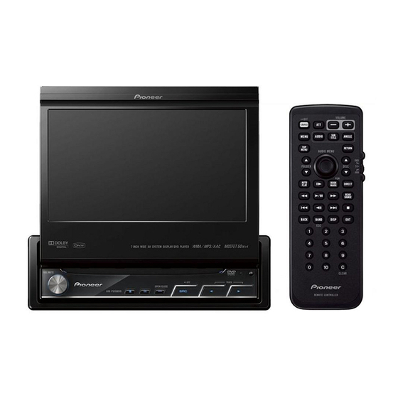
DVD AV RECEIVER
AVH-P5150DVD
AVH-P5150DVD
AVH-P5150DVD
This service manual should be used together with the following manual(s):
Model No.
Order No.
CX-3212
CRT3896
DTS and DTS Digital Out are registered trademartks and the DTS logos and Symbol are
trademarks of DTS, Inc.
Manufactured under license from Dolby Laboratories. Dolby, Pro Logic, and the double-D
symbol are trademarks of Dolby Laboratories.
For details, refer to "Important Check Points for Good Servicing".
PIONEER CORPORATION
PIONEER ELECTRONICS (USA) INC. P.O. Box 1760, Long Beach, CA 90801-1760, U.S.A.
PIONEER EUROPE NV Haven 1087, Keetberglaan 1, 9120 Melsele, Belgium
PIONEER ELECTRONICS ASIACENTRE PTE. LTD. 253 Alexandra Road, #04-01, Singapore 159936
PIONEER CORPORATION 2009
Mech.Module
MS5
DVD Mech. Module : Circuit Descriptions, Mech. Descriptions, Disassembly
4-1, Meguro 1-chome, Meguro-ku, Tokyo 153-8654, Japan
AVH-P5150DVD/XN/RC
/XN/RD
/XN/RI
Remarks
ORDER NO.
CRT4278
/XN/RC
K-ZZZ. JAN. 2009 Printed in Japan
Advertisement
Table of Contents

Related Manuals for Pioneer AVH-P5150DVD/XN/RC


Summary of Contents for Pioneer AVH-P5150DVD/XN/RC
- Page 1 PIONEER CORPORATION 4-1, Meguro 1-chome, Meguro-ku, Tokyo 153-8654, Japan PIONEER ELECTRONICS (USA) INC. P.O. Box 1760, Long Beach, CA 90801-1760, U.S.A. PIONEER EUROPE NV Haven 1087, Keetberglaan 1, 9120 Melsele, Belgium PIONEER ELECTRONICS ASIACENTRE PTE. LTD. 253 Alexandra Road, #04-01, Singapore 159936 PIONEER CORPORATION 2009 K-ZZZ.
-
Page 2: Safety Information
CAUTION Danger of explosion if battery is incorrectly replaced. Replaced only with the same or equivalent type recommended by the manufacture. Discord used batteries according to the manufacture's instructions. AVH-P5150DVD/XN/RC... - Page 3 To protect products from damages or failures during transit, the shipping mode should be set or the shipping screws should be installed before shipment. Please be sure to follow this method especially if it is specified in this manual. AVH-P5150DVD/XN/RC...
-
Page 4: Table Of Contents
11.4 DVD CORE UNIT ..........................174 11.5 COMPOUND UNIT(A) AND COMPOUND UNIT(B)................178 11.6 INVERTER PCB........................... 179 11.7 MONITOR PCB ............................ 180 11.8 TUNER BOX UNIT ..........................184 11.9 DRIVE UNIT ............................186 12. ELECTRICAL PARTS LIST ........................187 AVH-P5150DVD/XN/RC... -
Page 5: Service Precautions
Press EJECT key -> Grille is closed. * The key is valid at the point of being pressed (BEEP). To Leave the key makes grille opened. In order to exit "EJECT LOCK" mode, follow the same steps to enter this mode. AVH-P5150DVD/XN/RC... -
Page 6: Notes On Soldering
Compared with eutectic solders, lead-free solders have higher bond strengths but slower wetting times and higher melting temperatures (hard to melt/easy to harden). The following lead-free solders are available as service parts: Parts numbers of lead-free solder: GYP1006 1.0 in dia. GYP1007 0.6 in dia. GYP1008 0.3 in dia. AVH-P5150DVD/XN/RC... -
Page 7: Specifications
USB standard specification Gain ......±12 dB ..........USB 2.0 full speed Maximum current supply ..500 mA Frequency....200/500/1k/2k Hz USB Class....... MSC(Mass Storage Class) Q Factor ....0.35/0.59/0.95/1.15 (+6 dB File system......FAT16, FAT32 when boosted) AVH-P5150DVD/XN/RC... -
Page 8: Disc/Content Format
Signal-to-noise ratio..... 62 dB (IEC-A network) Infrared remote control Wavelength......945 nm Output ........typ; 10 mw/sr per Infrared Note Specifications and the design are subject to mod- ifications without notice due to improvements. 2.2 DISC/CONTENT FORMAT is a trademark of DVD Format/Logo Licensing Corporation. AVH-P5150DVD/XN/RC... -
Page 9: Panel Facilities
Press to open or close the LCD panel. Press and hold to turn the LCD panel hori- zontal temporarily from upright position. 6 SRC button This unit is turned on by selecting a source. Press to cycle through all the available sources. AVH-P5150DVD/XN/RC... -
Page 10: Remote Control
Press to change the viewing angle during DVD playback. RETURN button Press to display the PBC (playback control) menu during PBC playback. Remote control code: AVH or B Not used. buttons (DISC ) Not used. Remote control code: A Press to select the next/previous disc. AVH-P5150DVD/XN/RC... - Page 11 STOP ( ) button Press to stop playback. AUTO PLAY button Press to turn the DVD auto-playback function on or off. buttons (FOLDER ) Press to select the next/previous folder. AVH-P5150DVD/XN/RC...
-
Page 12: Fastening The Front Panel
Screws to 10. (Refer toPBC playback.) JGZ20P070FTC TV mode operation TV operations available with a Pioneer TV tuner (e.g. GEX-P5750TV(P)) can be controled with AVH mode. TV mode is not used with this unit. • For details concerning operation, refer to the TV tuner’s operation manuals. -
Page 13: Connection Diagram
2.4 CONNECTION DIAGRAM AVH-P5150DVD/XN/RC... - Page 14 AVH-P5150DVD/XN/RC...
- Page 15 AVH-P5150DVD/XN/RC...
- Page 16 AVH-P5150DVD/XN/RC...
-
Page 17: Basic Items For Service
Item to be checked regarding video Item to be checked regarding audio Block-noise Distortion Horizontal noise Noise Dot noise Volume too low Disturbed image (video jumpiness) Volume too high Too dark Volume fluctuating Too bright Sound interrupted Mottled color AVH-P5150DVD/XN/RC... -
Page 18: Pcb Locations
Main PCB Unit(SERVICE) Unit Number CZW5029 Unit Name Switch PCB Unit Unit Number CZW5028 Unit Name Volume PCB Unit Unit Number YWX5005 Unit Name DVD Core Unit Unit Number CWX3595 Unit Name Compound Unit(A) Unit Number CWX3559 Unit Name Compound Unit(B) AVH-P5150DVD/XN/RC... -
Page 19: Jigs List
3.3 JIGS LIST Bracket GGF1461 40-Pin + 20-Pin Relay PCB GGD1209 20-Pin FFC Main PCB Unit GGD1284 GGD1170 40-Pin FFC BBR 40-Pin FFC DVD Amp Unit Monitor PCB Cord CDE8589 DVD Mechanism Module AVH-P5150DVD/XN/RC... -
Page 20: Cleaning
Before shipping out the product, be sure to clean the following portions by using the prescribed cleaning tools: Portions to be cleaned Cleaning tools DVD pickup lenses Cleaning liquid : GEM1004 Cleaning paper : GED-008 Portions to be cleaned Cleaning tools Fans Cleaning paper : GED-008 AVH-P5150DVD/XN/RC... - Page 21 AVH-P5150DVD/XN/RC...
-
Page 22: Block Diagram
CN5001 DRAIVE UNIT CXC9160 REMOTE CN101 CONTROL ASS'Y CXC6317 CN441 DVD AMP UNIT DVD AMP UNIT(AMP) DVD AMP UNIT(SYSTEM) DVD AMP UNIT(POWER SUPPLY) CN121 JA951 CN851 CN852 JA751 IP-BUS INPUT DIGITAL CN3001 MINIJACK KEYBOARD UNIT RCA OUT VCR IN AVH-P5150DVD/XN/RC... - Page 23 CONNECTOR UNIT CN1901 CN901 CN550 WIREDGND WIREDAD WIRED CN401 P.B. VGND CN1251 REAR B.REM FANGND FANB MUTE MOTOR B.UP CN951 CN801 CN1852 CN1901 D E F MS5AVC2 MECHA MODULE CXK6631 VCR IN REAR VIEW REVERSE-GEAR CAMMERA SIGNAL IN AVH-P5150DVD/XN/RC...
-
Page 24: Block Diagram
48.000 IP-BUS BRXEN INPUT USBXTAL2 BSRQ ASENBO STBY XTAL2 BUSL+ X501 BUSL- XTAL1 CN550 RESET USBDM USBDP USB5V IC551 R5523N001B USBCNT USBCNT ACC5 USB5V USBFLG USBFLG VOUT CN601 FLMD0 TO 2/2 DRST FLASH WRITE CONNECTOR RESET RESET 3.3V VDD33 AVH-P5150DVD/XN/RC... - Page 25 IC1551 M62343FP Q1551 LEDCS Q1552 GREEN LEDCK Q1553 BLUE LEDDT KEY1 KEYIN1 USBCNT CN3001 USBCNT KEY2 KEYIN2 USBFLG ROT1 USBFLG ROTIN1 ROT2 ROTIN2 DSENS FLMD0 DSENS DSENS TO 2/2 DRST RESET SWVDD33 IC602 RESET VDD33 S-80827CNNB-B8M ILMB RESET RESET AVH-P5150DVD/XN/RC...
- Page 26 BEEP VDCNT BUZZER ILMB Q1522 ILMB ILM_ON X601 ACC33V 4.718592MHz IC1601 BA00BC0WFP ACC5 SWVDD33V Q1621 Q1622 SWVDD FIREWIRE PW Q1303 FWPW ACC5 Q1305 PPOWER ACC33 VDSENS ANGLE LFTPULS MTRS MTRPW IC441 TC74VHCT08AFTS1 MTR2 MTR1 MTRSEL TO 1/2 DEGOSW LEFSW AVH-P5150DVD/XN/RC...
- Page 27 JA951 OPTSENS DIGITAL OUT OPTOUT OPTG REAR CN1251 P1251 FANB SWBUP SYS+B EV12 VDD33 USB33 USB33 IC1031 S-1206B41-U3 ACC5 5.4V ACC33 SWVDD33 CN441(2/2) P442 SENPW ACC5 P441 ACC33 P443 ANGLEIN LIFTPUL MTRS CN101 MTRPW MTR2 MTR1 MTRSEL ANGLOSW LETSW AVH-P5150DVD/XN/RC...
- Page 28 VSENS VSENCE VIN3RF CN1951 VIN3 PR_A20 VIN4RF EXTRG1_SPD_SW EXTRG1 VIN4 SCLOCK SCLOCK VIN5 SDATA VIN6 SDATA EXTRG0 EXTRG0 CDMPD TRCCLK DVDMPD TRCCLK TRCD0 TRCDATA0 RFINN TRCD1 TRCDATA1 F+H_G+H TRCD2 TRCDATA2 E+G_E+F TRCD3 TRCDATA3 LPCO2 TRCST LPCO1 TRCST VCC33 VDD5 AVH-P5150DVD/XN/RC...
- Page 29 HOME SWITCH ACO1- ACO1+ CN1101 ACO2+ ACO2- TEMP 3.3V REG. IC1007 NJM2885DL1-33 VDD5 VCC33 CDMPD 78MD 1.2V REG. DVDMPD 65MD PU (DP8) IC1008 R1232D121B F+H_G+H F+H/G+H E+G_E+F E+G/E+F VCC12 Q1102 Q1104 LPCO2 LD(CD) Q1101 Q1103 LPCO1 LD(DVD) VREF VCC5 AVH-P5150DVD/XN/RC...
- Page 30 OSD33V Q5607 OSDPW XOUT X5601 5MHz PWRVI D/D CONVERTER IC5103 8V REGULATOR BD6171KV Q5103 PVCC1 1,2,5,6 OUT2 PVCC2 TH5601 TEMP. SENSOR PVCC PVCC3 PVCC4 TEMPSEN 3.3V REGULATOR Q5102 PVCC5 1,2,5,6 OUT1 OUT3 DDCON_SEL OUT4 OUT5 MVIPW CHARGE PUMP REGULATOR AVH-P5150DVD/XN/RC...
- Page 31 PDRV_C Q5204 VCC5V DIMDTY DIMMER DIMDTY NDRV_D VCC18V VCCM12V VR5201 2.5V REGULATOR RGE PUMP IC5203 GULATOR TC7SET08FUS1 IC5102 INVPUL INVPUL VOUT S-1132B25-U5 ON/OFF V25P V25AM 1.5V REGULATOR V25AS IC5101 VOUT INVBST INVBST S-1132B15-U5 ON/OFF V15M V15D Q5201 Q5206 Q5205 AVH-P5150DVD/XN/RC...
- Page 32 CN1901 ACC_ID ACC_ID TXIPOD TXIPOD RXIPOD RXIPOD ACC_PW ACC_PW CN901 iPod ACCDET ACCDET VOUT VOUT LOUT LOUT FMPWR FMPWR TUNER BOX UNIT FM/AM ANTENNA DSEN AM_ANT FM_ANT TC7WH08FU CN401 TUN+B TUN+B B.UP NJM2388F84 TUN3.3V TUN33V VDD_3.3 NJM2391DL1-33 ROM_VDD ROMVDD33 AVH-P5150DVD/XN/RC...
-
Page 33: Diagnosis
Source keys with Grille microcomputer may fail. operative If the time interval is not 500/300 msec, the oscillator may be defective. Source ON or Back Camera ON SYSPW Pin 6 Completes power-on operation. (After that, proceed to each source operation) AVH-P5150DVD/XN/RC... -
Page 34: Inspection Method Of Pickup Unit
Perform lens Is it OK? cleaned? cleaning Replace the PICK UP Check point: Error rate check Error rate check PICK UP Perform lens Is it OK? cleaned? cleaning Replace the PICK UP Ckeck parts Finished other than PICK UP AVH-P5150DVD/XN/RC... - Page 35 DVDLD1 VCC5_3 Status: [Foucs closed] of TEST MODE Mode: CD Disc Check Point Threshold Remarks: LD current TCD-782 CDLD1 – VCC5_3 (mV) 10 – 60(mA) CDLD1 VCC5_3 Notes: Please pay attention to the laser diode damage by static electricity. AVH-P5150DVD/XN/RC...
- Page 36 Watch carefully the value of ASMAX. Error rate check Status: [Tracking Closed] of TEST MODE Disc Check Point Threshold Remarks: less than GGV1025 ID: 40000 1.000E-03 less than GGV1025 ID: 200000 1.000E-03 less than TCD-782 ID: HOME Position 2.500E-03 AVH-P5150DVD/XN/RC...
-
Page 37: Diagnosis Flowchart
OK? Execute check 10. Go to FE section check. Repair the defective part. Go to FE section check. Normal? FE section check. Go to FE related Is FE section repair process. normal? Replace the unit. Normal? AVH-P5150DVD/XN/RC... - Page 38 <Check> Check the voltage at the “STANBY” test point while the power is on. Use the “DGND1” test point at the reference. Specification value Check point Module No. Unit STANBY-DGND1 VCC33 V- 0.6 V or more Side A DGND1 STANBY Fig 1.1: STANBY check point AVH-P5150DVD/XN/RC...
- Page 39 Specification value Check point Module No. Unit VDD5_3 - DGND1 5.0 ± 0.4 VCC33_3 - DGND1 3.3 ± 0.15 VCC12_1 - DGND1 1.2 ± 0.12 Side A VDD5_3 VCC33 DGND1 VCC12_1 Fig 2.2: VDD5, VCC33, VCC12 voltage check points AVH-P5150DVD/XN/RC...
- Page 40 <Check> Check the voltage at the “XRES” test point while the power is on. Use the “DGND1” test point at the reference. Check point Module No. Specification value Unit 1 XRES-DGND1 VCC33 × 0.7 or more Side A DGND1 XRES Fig 3.1: RESET check point AVH-P5150DVD/XN/RC...
- Page 41 <Check> Check the voltage at the “VSENS” test point while the power is on. Use the “DGND1” test point at the reference. Specification value Check point Module No. Unit VSENS - DGND1 VCC33 × 0.7 or more Side A DGND1 VSENS Fig 4.2: VSENS check point AVH-P5150DVD/XN/RC...
- Page 42 Specification value Check point Module No. Unit 27 MHz 2 IC1501 169pin ± 50 ppm Specification value Fig 5.2: Clock specification value Side A DGND1 IC1501 169pin Fig 5.3: 27 MHz check point AVH-P5150DVD/XN/RC...
- Page 43 Be careful as XCSM, XWE, XCAS, XRAS and XSCM of IC1481 are called differently in IC1501, namely NCSM, NWE, NCAS, NRAS, NCSM. IC1501 MA0~11 1481 DVD-LSI MDQ0~31 SDRAM XWE (NWE) XCAS (NCAS) XRAS (NRAS) XCSM (NCSM) DQM0 DQM1 DQM2 DQM3 Fig 6.1: SDRAM I/F AVH-P5150DVD/XN/RC...
- Page 44 56 ohm ± 5 % DQM2 IC1481 28pin IC1501 26pin 56 ohm ± 5 % DQM3 IC1481 59pin IC1501 27pin 56 ohm ± 5 % IC1481 22pin IC1501 8pin 56 ohm ± 5 % IC1481 23pin IC1501 10pin 56 ohm ± 5 % AVH-P5150DVD/XN/RC...
- Page 45 Side B Check point 1 (IC1481) Side A Check point 2 (IC1501) Fig 6.2: SDRAM I/F check point AVH-P5150DVD/XN/RC...
- Page 46 Use the “PGND3 and AGND1” test point at the reference. Check point Module No. Specification value Unit VD8_1 - PGND3 8.0 ± 0.4 VD - PGND3 8.0 ± 0.4 VCC5_1- AGND1 5.0 ± 0.1 Side A VD8_1 AGND1 PGND3 VCC5_1 Fig 7.2: VD8, VCC5 voltage check points AVH-P5150DVD/XN/RC...
- Page 47 Check with PGND and GNDAU being the reference. Check point Module No. Specification value Unit VD - PGND_3 8.0 ± 0.4 AVCC5 - GNDAU1 5.0 ± 0.1 Side A PGND3 GNDAU AVCC5 Fig 8.2: VD8, AVCC5 voltage check points AVH-P5150DVD/XN/RC...
- Page 48 33.868 8 MHz ± 300 ppm Specification value 1 Specification Specification value 2 value 3 Fig 9.2: Clock specification value Side A Check point 2 (IC1501 172 pin) Check point 1 (stylus) Fig 9.3: 27 MHz, DACCLK check point AVH-P5150DVD/XN/RC...
- Page 49 Waveform 2 LRCK VCC33 V-0.6 V or higher 0.4 V or lower Waveform 3 Specification value 2 Specification value 1 Fig 10.2: Serial 3 lines specification value Side A SRCK LRCK ADOUT3 Fig 10.3: Serial 3 lines check points AVH-P5150DVD/XN/RC...
- Page 50 1 400 ± 150 mV Waveform 4 1 400 ± 150 mV Waveform 4 Specification value is the root-mean-square value (rms). Fig 10.4: Analog audio out (LO, RO) specification value. Side A GNDAU1 Fig 10.5: Analog audio out check point AVH-P5150DVD/XN/RC...
- Page 51 Check 2pin cord after connecting it to a jig, etc. Specification value 2 Check point 1 (stylus) Specification value 1 Reference waveform 6 IEC VCC33 V-0.6 V or higher 0.4 V or lower Waveform 5 Side A Fig 10.6: Digital audio signal (IECOUT) check point AVH-P5150DVD/XN/RC...
- Page 52 ADOUT2 CLDCK AD3/DATA ADOUT3 DATA IEC/IPFLG IPFLG SBCK SBCK BMUTE BMUTE MCKENA High RIPP High EMPH EMPH EMPH Pins 1, 6, 8, 10, 12, 14, 16, 18, 20, 22 and 24 are GNDD. Fig 10.7: 6ch digital out/Ripping circuit AVH-P5150DVD/XN/RC...
- Page 53 VCC33 V-0.6 V or higher 0.4 V or lower SBCK VCC33 V-0.6 V or higher 0.4 V or lower RIPP VCC33 V x 0.3 V or lower Specification value 1 Specification value 2 Fig 10.8: 6ch digital out/Ripping specification value AVH-P5150DVD/XN/RC...
- Page 54 Side A SRCK LRCK ADOUT3 Side B ADOUT2 ADOUT1 ADOUT0 RIPP MCKENA SBCK Fig 10.9: 6ch digital out/Ripping check point AVH-P5150DVD/XN/RC...
- Page 55 Turn the volume (VR1671) to adjust the video level within the range of 1.0 ± 0.02 Vpp. The adjustment specification is 1.0 ± 0.02 Vpp. CN1901 AVCC5 HOST I/F IC1501 Q1701(NoMount) Video buffer circuit Video Q1702(NoMount) Video buffer circuit section Q1704(NoMount) Video buffer circuit Fig 11.3: Video circuit (component) AVH-P5150DVD/XN/RC...
- Page 56 Specification value BOTTOM PEAK Cb signal Specification value BOTTOM PEAK Cr signal Specification value BOTTOM 100% Color Bars signal Fig 11.4 Waveform for the case of component 100% Color Bars output Side A COMPO Fig 11.5: VIDEO signal check point AVH-P5150DVD/XN/RC...
- Page 57 (Refer to the FE test mode for the method of displaying the LD energizing time.) 2.If the second digit from the left of the energizing time display is showing E, such as “ E ”, it means that the flash memory has reached its life. Example: 0E000BB8 AVH-P5150DVD/XN/RC...
- Page 58 Reference voltage: DGND2 1 V/div. 500 nsec/div Waveform 7 G-> G-> Waveform 2 Waveform 5 [WHITE 100IRE] CH1 : LRCK CH1 : COMPO Reference voltage: GNDV1 200 mV/div. 10 usec/div Reference voltage: DGND2 1 V/div. 5 usec/div G-> Waveform 3 Waveform 6 AVH-P5150DVD/XN/RC...
-
Page 59: Error Code List
*5 AWM (Audio WaterMark): Electronic watermark. Information on the copyright owner or CCI (copy control information) are recorded so that illegally copied discs can be identified. *6 Notice as an error status will not be given *7 CPRM(Content Protection for Recordable Media) : A copyright protection technique for digital contents used for re-writable DVD or memory card. (DVD-VR model only) AVH-P5150DVD/XN/RC... -
Page 60: Usb Audio Player/Usb Memory Errors
AVH-P5150DVD/XN/RC... - Page 61 AVH-P5150DVD/XN/RC...
-
Page 62: Connector Function Description
5. IPBUS- 11. IPL- 5.FL- 5, 6. AUDIO INPUT 6.RL- 6. IPRG 7. REAR VIEW CAMERA INPUT 7.FL+ 8. VIDEO INPUT 8.RL+ 9. REAR MONITOR OUTPUT 9.P.B. 10. REVERSE GEAR SIGNAL INPUT 10.MUTE 11.B.REM 12.ILM 13.VGND 14.ACC 15.GND 16.B.UP AVH-P5150DVD/XN/RC... -
Page 63: Simple Operation Check Method
If you want to check the basic operation without the tuner box, do as mentioned bellow. Short between two lands of R678 on the B side of DVD AMP UNIT. SIDE B R678 Expansion R678 <NOTE> Do not forget to remove the solder or the part between lands of R678 after repair. AVH-P5150DVD/XN/RC... -
Page 64: Service Mode
Turning ACC ON [Operating Conditions] In detach off (including the case where the TUNER pack is not connected): Inoperable In DVD not connected (excluding rising time-out for 10 seconds): Operable In FLAP mechanism not connected: Operable Monitor not connected: Inoperable AVH-P5150DVD/XN/RC... - Page 65 Turning ACC ON [Operating Conditions] In detach off (including the case where the TUNER pack is not connected): Inoperable In DVD not connected (excluding rising time-out for 10 seconds): Operable In FLAP mechanism not connected: Operable Monitor not connected: Inoperable AVH-P5150DVD/XN/RC...
-
Page 66: Dvd Test Mode
In order to F close after focus search (S character measurement mode), set to Power_OFF first then power on again FEMIN level before F close. ASMAX level ENVMAX level FE normalization coefficient Spindle gain coefficient TEMAX level indication TEMIN level indication AVH-P5150DVD/XN/RC... - Page 67 Designation of digit by command (1) and (2). UP/DOWN of numbers by command (3) and (4). Fix by command (5). Error occurrence at Power_OFF [Note] If an error occurs at Power_OFF, reset cannot be made. In such a case, it is necessary to turn the power off and start the test mode once again. Error display AVH-P5150DVD/XN/RC...
- Page 68 [Note] If the power on time is 999999 hours or more, it is always reported as 999999 hours. [Note] If the power on time is “*E** ****”, the value may not be correct due to the life of the flash memory. AVH-P5150DVD/XN/RC...
-
Page 69: Calibration Test Mode
6.3 CALIBRATION TEST MODE Refer to “Touch Panel Adjustment” from the page 92 in “Each setting and adjustment”. 6.4 MONITOR TEST MODE Refer to “Monitor Adjustment” from the page 100 in “Each setting and adjustment”. AVH-P5150DVD/XN/RC... -
Page 70: Disassembly
Fig.1 How to separate the Drive Unit and the (Rear Side) Chassis Assy (Fig. 2) Remove the seven screws and then sepa- rate the Drive Unit and the Chassis Assy. (Left Side) Drive Unit Chassis Assy (Right Side) Fig.2 AVH-P5150DVD/XN/RC... - Page 71 Remove the four screws and then lift the DVD Mechanism Module toward the Left Side. DVD Mechanism Module Disconnect the two connectors and then remove the DVD Mechanism Module. Drive Unit Disconnect the connector and then remove the Drive Unit. DVD Amp Unit Fig.3 AVH-P5150DVD/XN/RC...
- Page 72 Straighten the tabs at two locations indicated and then remove the Holder. Holder Fig.4 Removing the DVD Amp Unit (Fig.5) Remove the three screws. Straighten the tabs at three locations indi- cated and then remove the DVD Amp Unit. DVD Amp Unit Fig.5 AVH-P5150DVD/XN/RC...
- Page 73 Removing the Motor Unit, the Drive Unit can operate to lead to the Monitor Assy. Motor Unit Remove the two screws and then remove the two Guids(Right side, Left side). Pull out the Monitor Assy in the direction indicated by an arrow. Fig.6 AVH-P5150DVD/XN/RC...
- Page 74 Monitor Assy. Disconnect the connector. Monitor Assy Cover Unit Inverter PCB Remove the two screws. Disconnect the two connectors and then remove the Inverter PCB. Disconnect the connector and then remove the LCD Assy. LCD Assy Monitor Assy Fig.7 AVH-P5150DVD/XN/RC...
- Page 75 7. Disconnect the connector of the 8-12 detection flexible PCB from the PCB. Fig 2 Module PCB Short Connector Connector (8-12 detection flexible) (pick up flexible) Solder land (load motor, lead wire of the clamp SW.) Connector (SPDL flexible) Fig 3 AVH-P5150DVD/XN/RC...
- Page 76 Furthermore, make sure to hang the main shaft holding spring permanently. Holding plate spring Main shaft PU unit Main shaft holding spring Sub shaft Fig 5 CRG chassis temporary hanging section Temporary hanging Permanent hanging AVH-P5150DVD/XN/RC...
-
Page 77: Each Setting And Adjustment
Laser didoes may be damaged, if the volume switch for measurement devices have the same electrical potential the laser power adjustment of the pick up unit, is turned. as the minus side of the probe, the body frame of the measurement device should be set to floating ground. AVH-P5150DVD/XN/RC... - Page 78 Oscilloscope Symptom in case the adjustment is not adequate: Worsening of the error rate 10 (Normally 10 or less.) Large RF jitter RF waveform distortion Tracking drawing/Unstable servo * Caution: Do not look into the laser light during adjustment. AVH-P5150DVD/XN/RC...
- Page 79 Referring to the connection diagram, connect an oscilloscope so that RF signal can be monitored using AGND2 as the reference. AGND2 Oscilloscope In case of method 2: There is no need for setting equipment. Please go on to step 3. 3. Turn on the power in the test mode, and load the adjustment disc (GGV1025). AVH-P5150DVD/XN/RC...
- Page 80 5th digit, and select [3] Cursor Up and press [Enter] for 4 times. When the display is changed to ID: 40000, select [5] Start ID Search and press [Enter]. * If Search operation is failed, please restart from the top menu of ServMecha in the test mode. AVH-P5150DVD/XN/RC...
- Page 81 10. In FE Test Mode screen, after confirming the disc is stopped by Power OFF, eject the disc by Disc Eject. 11. Apply adhesive agent for fixing the skew, and lock the screws. Refer to the next section for the part to be adhered. AVH-P5150DVD/XN/RC...
- Page 82 Screw locking adhesive location(1401M : produced by THREE BOND) Screw locking adhesive location Apply the locking agent for more than half of the screw head circumference. * Caution: The locking agent shall not overflow to outside of the PU case. AVH-P5150DVD/XN/RC...
- Page 83 Precautions in handling the PU. * Caution: Do not touch the shaded section in the drawing below. RF level adjustment section Do not touch the optical parts. Do not touch the springs. Hologram (be careful for the static electricity) GRT adjustment section AVH-P5150DVD/XN/RC...
-
Page 84: Dvd Amp Unit Adjustment
8.2 DVD AMP UNIT ADJUSTMENT DVD AMP UNIT(SIDE A) - Adjustment Point VR1401 DVD AMP UNIT(SIDE B) TP1401 TP605 TP1406 TP607 TP1402 AVH-P5150DVD/XN/RC... - Page 85 AVH-P5150DVD/XN/RC...
-
Page 86: Inverter Pcb Adjustment
8.3 INVERTER PCB ADJUSTMENT - Adjustment Point INVERTER PCB(SIDE A) INVERTER PCB(SIDE B) VR5201 INVPUL PWRFL2 DIMDTY AVH-P5150DVD/XN/RC... - Page 87 AVH-P5150DVD/XN/RC...
-
Page 88: Monitor Pcb Adjustment
8.4 MONITOR PCB ADJUSTMENT MONITOR PCB(SIDE B) - Adjustment Point -12V VCC8V PWRVI AVH-P5150DVD/XN/RC... - Page 89 AVH-P5150DVD/XN/RC...
- Page 90 AVH-P5150DVD/XN/RC...
- Page 91 AVH-P5150DVD/XN/RC...
-
Page 92: Touch Panel Adjustment
In case the adjustment value has been initialized. Calibration check When line calibration check has never been executed or when calibration check ended with NG or was aborted. When EEPROM is initialized. When adjustment value is initialized (Factory Calibration Init is executed) from Data initialize menu. AVH-P5150DVD/XN/RC... - Page 93 C h e c k t h e V a l u e X/Y information of [MIN] and [MAX] of the outermost circumference are displayed. [BEFOR] indicates the value stored in the EEPROM. [AFTER] indicates MIN/MAX of the A/D value currently captured. AVH-P5150DVD/XN/RC...
- Page 94 1 2 3 4 5 6 7 8 9 10 11 12 13 14 15 16 17 18 19 20 21 22 23 24 25 26 27 28 29 30 31 32 33 34 35 36 37 38 39 40 [ A . M E N U ] R e t u r n M e n u The data written is as follows. Adjustment NG information. [Key operation specifications] Remote Operational controller description To top menu MENU_ENTER AVH-P5150DVD/XN/RC...
- Page 95 1 2 3 4 5 6 7 8 9 10 11 12 13 14 15 16 17 18 19 20 21 22 23 24 25 26 27 28 29 30 31 32 33 34 35 36 37 38 39 40 This point is intended to end the calibration inspection, and therefore, the corrected value of this point is not obtained. AVH-P5150DVD/XN/RC...
- Page 96 CALIBRATION: The coordinate (X direction, Y direction), which is the result of applying the correction by calibration to the normalized coordinate, is displayed. [Key operation specifications] Remote Operational controller description To top menu MENU_ENTER AVH-P5150DVD/XN/RC...
- Page 97 1 2 3 4 5 6 7 8 9 10 11 12 13 14 15 16 17 18 19 20 21 22 23 24 25 26 27 28 29 30 31 32 33 34 35 36 37 38 39 40 [ A . M E N U ] R e t u r n M e n u AVH-P5150DVD/XN/RC...
- Page 98 For example, the coordinate of 1st point is shown in the following figure. 226 227 OK range The area in which the coordinate exists X = 226 , Y = 29 Regularized coordinates X(DEC) Y(DEC) 226.0 29.0 226.0 206.0 35.0 206.0 35.0 29.0 * Truncate after decimal point AVH-P5150DVD/XN/RC...
- Page 99 When the adjusted value has been initialized (Data initialize). When the EEPROM has been initialized. [key operation spesifications] Remote Operational controller description Determination of initializing item BACK Selected cursor up movement Selected cursor down movement To top menu MENU_ENTER AVH-P5150DVD/XN/RC...
-
Page 100: Monitor Adjustment
Select a item desired to be adjusted by using the key allocated for "selection cursor up/down movement", and value is adjusted by using the key allocated for "Item content adjustment +/-". Moreover, the page is switched with a key allocated in "Menu page select +/-". The page changes by the toggle. AVH-P5150DVD/XN/RC... - Page 101 1 2 3 4 5 6 7 8 9 10 11 12 13 14 15 16 17 18 19 20 21 22 23 24 25 26 27 28 29 30 31 32 33 34 35 36 37 38 39 40 < F L I C K E R A D J U S T > COM DC AVH-P5150DVD/XN/RC...
- Page 102 1 2 3 4 5 6 7 8 9 10 11 12 13 14 15 16 17 18 19 20 21 22 23 24 25 26 27 28 29 30 31 32 33 34 35 36 37 38 39 40 < L I N E 2 > AVH-P5150DVD/XN/RC...
- Page 103 1 2 3 4 5 6 7 8 9 10 11 12 13 14 15 16 17 18 19 20 21 22 23 24 25 26 27 28 29 30 31 32 33 34 35 36 37 38 39 40 < L I N E 5 > AVH-P5150DVD/XN/RC...
- Page 104 1 2 3 4 5 6 7 8 9 10 11 12 13 14 15 16 17 18 19 20 21 22 23 24 25 26 27 28 29 30 31 32 33 34 35 36 37 38 39 40 < L I N E 7 > AVH-P5150DVD/XN/RC...
- Page 105 S A 4 6 H L O W S A 4 7 H L O W S A 4 8 H L O W S A 4 9 H L O W S A 4 A H L O W AVH-P5150DVD/XN/RC...
- Page 106 1 2 3 4 5 6 7 8 9 10 11 12 13 14 15 16 17 18 19 20 21 22 23 24 25 26 27 28 29 30 31 32 33 34 35 36 37 38 39 40 < D I M M E R A D J U S T > AVH-P5150DVD/XN/RC...
- Page 107 [YS sampling phase 1, AD sampling phase B/G/R, YS internal delay adjustment] Displayed value(=adjust EEPROM written Double window IC register value)(DEC) value value Line adjustment 6 menu [Brightness R/G/B] Displayed value(=adjust EEPROM written Double window IC register value)(DEC) value value 011111 (MAX) AVH-P5150DVD/XN/RC...
-
Page 108: Exploded Views And Parts List
Screw adjacent to mark on the product are used for disassembly. For the applying amount of lubricants or glue, follow the instructions in this manual. (In the case of no amount instructions,apply as you think it appropriate.) 9.1 PACKING AVH-P5150DVD/XN/RC... - Page 109 Polyethylene Bag CEG1042 27-5 Caution Card CRP1387 Remote Control Unit CXC6317 Air Cushioned Bag CEG1081 (2) CONTRAST TABLE AVH-P5150DVD/XN/RC, AVH-P5150DVD/XN/RD and AVH-P5150DVD/XN/RI are constructed the same except for the following: Mark Description AVH-P5150DVD/XN/RC AVH-P5150DVD/XN/RD AVH-P5150DVD/XN/RI Unit Box CHG6763 CHG6764 CHG6765...
-
Page 110: Exterior(1)
9.2 EXTERIOR(1) Panel Assy AVH-P5150DVD/XN/RC... - Page 111 Connector(CN1251) CKS4822 Connector(CN852) CKS4825 Connector(CN441) CKS5496 Connector(CN121) CKS5566 Connector(CN851) CKS5644 Connector(CN801) CKS5660 Connector(CN601) CKS5757 Connector(CN550) CKS5967 Holder CND4275 Holder CND4276 Holder CND4278 Holder CND4279 Connector(JA1901) CKS5683 Connector(CN1901) CKS5861 Holder CND4277 Fan Motor CXM1262 Screw PMZ20P160FTC IC(IC151) PAL007C Resistor RS1/2PMF102J AVH-P5150DVD/XN/RC...
-
Page 112: Exterior(2)
9.3 EXTERIOR(2) Drive Unit AVH-P5150DVD/XN/RC... - Page 113 CND4272 Sheet CNN1748 Sheet CNN1749 Sheet CNN1750 Insulator CNN2209 Monitor Unit CWN4088 Connector(CN5201) CKS4428 Connector(CN5004) CKS5033 Connector(CN5602) CKS5033 Connector(CN5002) CKS5105 Connector(CN5501) CKS5111 Connector(CN5001) CKS5698 Terminal(KN5401) CKF1068 LCD Module CWX3264 DVD Mechanism Module(MS5AVCOD) CXK6631 Cover Unit CXE1302 Flat Cable CDE8886 AVH-P5150DVD/XN/RC...
-
Page 114: Exterior(3)
9.4 EXTERIOR(3) AVH-P5150DVD/XN/RC... - Page 115 CBL1761 Button CAI1460 Screw(M2 x 3) CBA2078 Screw(M2 x 3) CBA2079 Spring CBH2681 Spring CBH2682 Spring CBH2683 Holder CND3852 Holder CND3853 CNV8571 CNV8572 CNV8573 Connector CKS4658 Flexible PCB CNQ2708 Panel Unit CXE1519 Cord Assy CDP1013 > Fuse(10 A) CEK1136 AVH-P5150DVD/XN/RC...
-
Page 116: Exterior(4)
9.5 EXTERIOR(4) The application position of grease is referred to page 118 and page 119. : GEM1073 AVH-P5150DVD/XN/RC... - Page 117 CNN2051 Insulator CNN1583 Insulator CNN2168 Gear CNR1855 Gear CNR1856 Gear CNR1857 Gear CNR1859 Gear CNR1860 Gear CNR1861 Gear CNR1862 Gear CNR1864 Gear CNR1925 Gear CNR1926 Gear CNV8980 Gear CNV8981 Gear CNV8983 Gear CNV8984 Gear CNV8985 Rack CNV8995 Rack CNV8996 AVH-P5150DVD/XN/RC...
- Page 118 The gear assembly figure of the Drive Unit CNR1861 CNV8980 CNV8984 CNR1926 CNR1860 CNR1862 CNV8981 CNV8985 CNR1859 Grease HOLDER (CND3245) HOLDER HOLDER GEAR (1) : GEM1011 (2) : GEM1043 (3) : GEM1047 AVH-P5150DVD/XN/RC...
- Page 119 (1) : GEM1011 (2) : GEM1043 (3) : GEM1047 (4) : GEM1024 (5) : GEM1072 (6) : GEM1071 AVH-P5150DVD/XN/RC...
-
Page 120: Dvd Mechanism Module
9.6 DVD MECHANISM MODULE (A) : GEM1045 (B) : GEM1043 (C) : GEM1024 (D) : GEM1050 AVH-P5150DVD/XN/RC... - Page 121 CNC9933 Motor(SPDL)(M3) CXM1362 Holder CND5006 Screw JFZ20P018FTC Frame CND2250 Washer YE20FTC Holder CND2251 Pickup Unit(Service) CXX2118 Screw IMS20P030FTC Holder CND3936 Sheet CNM6883 Collar CNV9570 Sheet CNM8697 Shaft CLA4771 Sheet CNM9658 Sheet CNM9407 CNV7156 Clamper CNV7158 Roller CNV7165 Rack CNV7175 AVH-P5150DVD/XN/RC...
-
Page 122: Schematic Diagram
BIAS2 R5-2 C345 1u/16 B.CAM GNDV GND2 R5-1 R339 C346 1u/16 AV SELECTOR IN AUX:+2.2dBs VCR:+8.2dBs iPod:+1.3dBs USB:+0.6dBs PREOU S1G-6904G2P VCR IN BGSENS R304 D301 POWER D302 R305 SENS EVOL S1G-6904G2P R311 AV SEL GNDA VBS AJU ANALOG BUS AVH-P5150DVD/XN/RC... - Page 123 The > mark found on some component parts indicates discrete resistors. the importance of the safety factor of the part. Symbol indicates a capacitor. Therefore, when replacing, be sure to use parts of No differentiation is made between chip capacitors and identical designation. discrete capacitors. AVH-P5150DVD/XN/RC...
- Page 124 AVH-P5150DVD/XN/RC...
- Page 125 AVH-P5150DVD/XN/RC...
- Page 126 AVH-P5150DVD/XN/RC...
- Page 127 AVH-P5150DVD/XN/RC...
-
Page 128: Dvd Amp Unit(System)(Guide Page)
AGND TP813 VGND DAP202U TP814 R804 TC7WH08FU FLASH WRITE CONNECTOR COMPOSIT SWVDD33 MS_L VGND KEYBOARD UNIT 8.0V 8.0V 3.3V DVD/CD:+5.1dBs GNDV ILMA GNDD ILMB VGND MS_V R862 VGND GNDD VGND CN851 R805 GNDD GNDDDC WAKEUP WAKEUP GNDD TP802 CN3001 AVH-P5150DVD/XN/RC... - Page 129 2SA1576A(RS) 2SC4081(QRS) BLUE LEDDT TP556 D501 R706 GNDD Q1553 PRDY 2SC4081(QRS) IC701 M62343FP EMZC6.8N TP951 GNDD GNDD 5.2V CN951 L951 CN550 IC951 TP952 CTF1389-A GNDD R951 TC7WH08FU USB:+0.6dBs R955 CN1852 OUTY GNDD TC7SET08FUS1 S/PDIF IN GNDD JA951 DIGITAL OUT AVH-P5150DVD/XN/RC...
- Page 130 AVH-P5150DVD/XN/RC...
- Page 131 AVH-P5150DVD/XN/RC...
- Page 132 CN901 CN1901 AVH-P5150DVD/XN/RC...
- Page 133 AVH-P5150DVD/XN/RC...
-
Page 134: Dvd Amp Unit(Power Supply)
ACC5 R1505 ACC33 ACC3R3 D140 RSX2 (D%) ILM_ON 3.4V R1602 R1603 GNDDDC 2.2k SWVDD33V GNDD SWVDD33 Q1622 3.3V 2SB1132(QR) Q1702 TP1701 2SB1708 5.1V D1702 RSX201L-30 LITTEL 1.25A R1701 SWVDD Q1621 DTC114EUA R1702 Q1701 GNDD 2SC4081(QRS) 5.6k R1704 VDCNT GNDD AVH-P5150DVD/XN/RC... - Page 135 FAN REG 2125 1051 PWVI 1301 FIREWIRE PW 3216 Q1701 1071 PWFL 1401 DD CONVERTOR 2SC4081(QRS) 1101 SYS8.4V 1501 1151 SW B.UP 1521 ILM A&B 1201 HIOUT12V 1601 ACC33V 1251 FAN REG 1621 SWVDD33V 1101 SYS8.4V 1701 1151 SW B.UP AVH-P5150DVD/XN/RC...
-
Page 136: Ipod Connector Unit
TXIPOD ACCDET TP1903 ACCDET ACC_ID IPODGND TP1902 ACCPW ACC_PW ACC_PW VOUT TP1905 IPODGND IPODGND TP1901 ACCDET IPOD_VG TP1904 ROUT ROUT ROUT IPOD_AG VOUT VOUT IPOD_AG LOUT RXIPOD RXIPOD LOUT LOUT ACCID ACC_ID iPod:+1.3dBs TXIPOD FWPWR TXIPOD FWGND FWPWR FWGND AVH-P5150DVD/XN/RC... -
Page 137: Keyboard Unit
ROT1 S3001 KEY2 S3008 CSG1155-A ROT2 CSG1155-A FORWARD ILMGND S3005 CSG1155-A DGND R3001 DSENS CSG1155-A R3009 DGND DGND DGND ILMGND ILMB DGND 8.1V ILMGND (RED) (GREEN) R3021 R3029 R3035 (BLUE) Q3021 Q3022 Q3023 R3022 R3030 R3036 UMX1N UMX1N ILMGND AVH-P5150DVD/XN/RC... -
Page 138: Dvd Core Unit(1/2)(Guide Page)
10.6 DVD CORE UNIT(1/2)(GUIDE PAGE) RF SIGNAL FOCUS SERVO LINE TRACKING SERVO LINE CARRIAGE SERVO LINE SPINDLE SERVO LINE CWW1763 AVH-P5150DVD/XN/RC... - Page 139 DVD CORE UNIT(1/2) M2,M3 CWW1764 AVH-P5150DVD/XN/RC...
- Page 140 AVH-P5150DVD/XN/RC...
- Page 141 AVH-P5150DVD/XN/RC...
- Page 142 AVH-P5150DVD/XN/RC...
- Page 143 AVH-P5150DVD/XN/RC...
-
Page 144: Dvd Core Unit(2/2)
10.7 DVD CORE UNIT(2/2) CN951 AVH-P5150DVD/XN/RC... - Page 145 DVD CORE UNIT(2/2) CN801 AVH-P5150DVD/XN/RC...
-
Page 146: Compound Unit(A) And Compound Unit(B)
10.8 COMPOUND UNIT(A) AND COMPOUND UNIT(B) COMPOUND UNIT(A) Q1299 R1298 R1299 CPT231SCTD S1205 CSN1070 CN1301 DISC SENS DISC SENS S1203 CSN1069 CSN1070 S1204 S1202 CSN1069 12cm S1201 CSN1069 COMPOUND UNIT(B) CLAMP CSN1067 AVH-P5150DVD/XN/RC... - Page 147 AVH-P5150DVD/XN/RC...
-
Page 148: Monitor Pcb(Monitor)(Guide Page)
GNDOSD CN5004 L5001 14.1V CTH1338-A PWRFL 10 PWRFL 9 PWRFL 8 NC 7 GNDFL 6 GNDFL 5 CN5602 GNDFL 4 INVPUL GNDFL INVPUL INVPUL DIMMER DIMMER DIMDTY INVBST INVBST INVBST GNDFL ANALOG BUS ANALOG OSD PART PinP PinP CONTRO AVH-P5150DVD/XN/RC... - Page 149 IC5503 AOUTPUT C5515 R5508 GNDD 4.9V R5528 A-INPUT 1u/16 COMDC BOUTPUT A+INPUT (D%) B-INPUT GNDD B+INPUT IC5501 L5502 M62343FP NJM2100V 4.9V VCCM12V 0.1m -12.0V R5501 MONITOR UNIT GNDD Consists of COMAC PinP MONITOR PCB PinP CONTROL INVERTER PCB GNDD AVH-P5150DVD/XN/RC...
- Page 150 LCD MO AVH-P5150DVD/XN/RC...
- Page 151 LCD MODULE AVH-P5150DVD/XN/RC...
- Page 152 AVH-P5150DVD/XN/RC...
- Page 153 TOUCH PANEL MODULE AVH-P5150DVD/XN/RC...
-
Page 154: Monitor Pcb(Osd)(Guide Page)
REM 19 ILMB ILMB 8.0V ILMB SWVDD33 SWVDD33 SWVDD33 21 3.3V SWVDD33 22 SWVDD33 23 GNDOSD 3.3V GNDOSD 24 SWVDD33 GNDOSD 25 R5027 GNDOSD 26 R5028 GNDOSD GNDV GNDV 27 MONVBS MONVBS 28 GNDV 29 GNDV GNDILM GNDILM 30 GNDOSD AVH-P5150DVD/XN/RC... - Page 155 GNDOSD R5853 GNDOSD GNDD GNDOSD OSDR Q5801 2SA1774(QR) GNDOSD Q5802 OSDG UMT1N OSDB GNDOSD GNDOSD CONNECTOR PART 5001 OSD uCON PART 5601 ANALOG BUS TOUCH PANELPART 5701 OSD IC PART 5801 MONITOR UNIT Consists of MONITOR PCB INVERTER PCB AVH-P5150DVD/XN/RC...
- Page 156 AVH-P5150DVD/XN/RC...
- Page 157 AVH-P5150DVD/XN/RC...
- Page 158 AVH-P5150DVD/XN/RC...
- Page 159 AVH-P5150DVD/XN/RC...
-
Page 160: Inverter Pcb
C5213 2SC4617(RS) (D%) INVPUL VDDA PGND INVPUL 1u/16 DIMDTY GNDA DIMDTY GNDFL 0.1u/50 INVBST V2500 INVBST C5208 GNDFL LPWM DIMDTY PDRV_C C5212 GNDFL 0.047u R5206 D5202 COMP NDRV_D 3300p/50 1SS355 4.7k OZ961ISN R5210 CHIP SIZE LEGEND 1608 2125 3216 AVH-P5150DVD/XN/RC... - Page 161 1u/16 TS8M1 FET2 GNDFL T5201 CTT1119-A GNDFL Q5208 C5219 VR5201 CCG1260-A CCP1450-A 220p/50 (22k) R5227 R5214 (D%) (D%) TS8M1 GNDFL C5217 0.047u/50 GNDFL INVBST R5218 R5219 7.8V 100k Q5205 2SC4617(RS) GNDFL MONITOR UNIT Consists of MONITOR PCB INVERTER PCB AVH-P5150DVD/XN/RC...
-
Page 162: Tuner Box Unit
TP13 COMP DGND RFGND 3.3V (MAX8mA) DGND VDD33 TP36 ROM_VDD CTF1379 OSCGND LDET RFGND CE11 CE21 TUN+B LDET1 (MAX200mA) TP11 8.4V TP12 FM_ANT TP34 RF_GND TP35 AM_ANT FM/AM TUNER UNIT RFGND 0.01u/50 1000p/50 RFGND DGND RFGND BEGN RFGND DGND AVH-P5150DVD/XN/RC... - Page 163 ROMVDD33 TP23 LDET1 LDET TP24 CN401 TP25 DGND TP21 RDS_LOCK TP26 DSEN TP27 CE11 SW.BUP TP28 TUN33V TP29 BEGND 3.3V TP30 SW.BUP B.UP TP31 TP32 OSCGND TP33 CE21 LDET1 TC7WH08FU RFGND BEGND DGND RFGND TUNER_BUS RFGND BEGND RFGND RFGND AVH-P5150DVD/XN/RC...
-
Page 164: Drive Unit
10.13 DRIVE UNIT MAIN PCB UNIT(SERVICE) CN441 AVH-P5150DVD/XN/RC... - Page 165 SWITCH PCB UNIT VOLUME PCB UNIT AVH-P5150DVD/XN/RC...
-
Page 166: Waveforms
0.2 V/div(AC) 50 ns/div 0.2 V/div(AC) 50 ns/div Inner peripheral Peripheral DVDRF(x 1.3 ZCAV) DVDRF(x 5 CAV DVDRF(x 5 CAV 0.5 V/div 100 us/div 0.1 V/div 100 us/div 0.1 V/div 100 us/div DVDRF(BD1 mm) Interval FWD Interval REV 2.2 V VHALF VHALF AVH-P5150DVD/XN/RC... - Page 167 1 ms/div B + -B - Play TD Focus Close ID search Inside t Outside VHALF VHALF 0.5 V/div 20 ms/div 0.5 V/div 500 us/div 0.5 V/div 500 us/div Play FD Focus Jump L0tL1 Focus Jump L1tL0 VHALF VHALF VHALF AVH-P5150DVD/XN/RC...
-
Page 168: Pcb Connection Diagram
R604 R618 R951 C802 R619 R633 C804 CN951 R616 R617 CN1852 C1701 P801 R607 R807 R801 R628 C617 R677 CN1901 R806 C550 R555 C810 R802 R556 C809 IC550 R803 R558 R557 R804 R559 C551 R805 2530 C806 C805 FRONT AVH-P5150DVD/XN/RC... - Page 169 R694 D1403 C504 R683 C1416 R692 D1402 R522 R687 C1405 C1404 R141 R691 C501 R693 R521 D853 L1401 R679 Q1032 C1002 Q1401 R685 IC1031 P1402 C1033 R1035 R665 R707 IC701 BZ601 R857 C1601 R1602 C701 R706 R697 L701 FRONT AVH-P5150DVD/XN/RC...
- Page 170 C503 R1032 TP607 C1417 R1031 D851 R862 R676 D852 IC1401 C1418 C1003 R1420 R1418 CN851 R1407 R1406 Q1501 R1501 D1031 R1402 R1403 Q1502 C1402 CN501 Q1403 TP1402 IC1601 C1521 C1603 R1522 C1541 C1602 R1542 Q1522 R1523 R1543 Q1542 CN3001 AVH-P5150DVD/XN/RC...
- Page 171 R606 D1051 R623 C612 R614 C616 TP605 C608 R1701 R602 TP607 R603 R615 C609 R1703 D852 D601 R519 R1705 R624 Q1701 R601 C601 CN851 Q1702 R1704 R1702 IC602 D1702 R642 R704 R703 C811 R701 R700 CN601 R699 R698 CN3001 AVH-P5150DVD/XN/RC...
-
Page 172: Ipod Connector Unit
11.2 iPod CONNECTOR UNIT iPod CONNECTOR UNIT SIDE A iPod CONNECTOR UNIT SIDE B iPod JA1901 CN1901 CN901 AVH-P5150DVD/XN/RC... -
Page 173: Keyboard Unit
R3001 CN3001 REVERSE CN851 D3025 S3004 C3025 R3006 SOURCE C3026 S3003 C3021 R3004 S3007 OPEN/ D3021 CLOSE Q3021 S3008 R3022 D3023 R3008 Q3023 R3035 D3022 S3006 EJECT Q3022 R3007 R3029 D3011 C3012 D3024 IC3011 C3011 R3003 R3002 ATT/VOL S3002 AVH-P5150DVD/XN/RC... -
Page 174: Dvd Core Unit
11.4 DVD CORE UNIT DVD CORE UNIT PICKUP UNIT (SERVICE) M2, M3 CN951 AVH-P5150DVD/XN/RC... - Page 175 SIDE A CN801 UNIT AVH-P5150DVD/XN/RC...
- Page 176 DVD CORE UNIT AVH-P5150DVD/XN/RC...
- Page 177 SIDE B AVH-P5150DVD/XN/RC...
-
Page 178: Compound Unit(A) And Compound Unit(B)
11.5 COMPOUND UNIT(A) AND COMPOUND UNIT(B) COMPOUND UNIT(A) COMPOUND UNIT(B) Q1299 R1298 CLAMP R1299 S1205 S1204 DISC SENS S1203 DISC SENS S1202 12cm S1201 CN1301 AVH-P5150DVD/XN/RC... -
Page 179: Inverter Pcb
C5213 C5207 C5212 C5220 C5210 D5205 R5210 C5211 C5208 R5216 R5209 Q5203 R5208 Q5207 R5203 Q5204 R5207 R5206 Q5206 C5221 Q5202 D5204 D5202 R5215 R5205 D5201 Q5205 R5217 R5218 R5219 CN5004 PWRFL2 R5220 C5205 D5206 CN5602 IC5201 DIMDTY C5204 AVH-P5150DVD/XN/RC... -
Page 180: Monitor Pcb
R5128 R5524 R5530 L5506 C5529 C5527 C5528 C5530 R5127 R5130 C5512 R5531 R5131 D5107 D5109 D5108 L5116 CN5501 Q5501 R5532 Q5101 C5150 L5504 R5533 Q5502 R5526 R5501 C5154 C5138 IC5501 L5104 C5503 L5001 CN5004 C5005 C5006 CN5602 LCD MODULE AVH-P5150DVD/XN/RC... - Page 181 CN5002 D5601 C5605 C5013 L5104 R5704 R5703 D5003 R5030 Q5608 C5610 R5706 R5705 C5003 C5609 Q5001 D5002 L5701 5001 R5029 R5010 R5043 C5002 C5012 Q5607 R5647 CN5001 R5009 CN5003 R5648 L5605 R5008 CN5009 R5007 R5001 C5006 TOUCH PANEL CN441 AVH-P5150DVD/XN/RC...
- Page 182 MONITOR PCB VCC8V PWRVI AVH-P5150DVD/XN/RC...
- Page 183 SIDE B IC5001 KN5401 -12V AVH-P5150DVD/XN/RC...
-
Page 184: Tuner Box Unit
11.8 TUNER BOX UNIT TUNER BOX UNIT SIDE A CN401 FM/AM ANTENNA AVH-P5150DVD/XN/RC... - Page 185 TUNER BOX UNIT SIDE B C6 C7 AVH-P5150DVD/XN/RC...
-
Page 186: Drive Unit
D101 C108 C102 UNIT C106 VR101 IC104 C110 IC102 S101 C109 Angel sense R109 CN102 C105 Angel sw C103 R117 C107 C104 ANGLE MOTOR SLIDE MOTOR CN103 VOLUME PCB UNIT CN102 SIDE B CN103 IC103 IC105 J K L AVH-P5150DVD/XN/RC... -
Page 187: Electrical Parts List
Unit Number : CWN3852(RC) Unit Number : CWN3853(RD) Q 951 (A,85,94) Chip Transistor 2SA1576A Q 1001 (B,113,32) Transistor 2SB1184F5 Unit Number : CWN3854(RI) Q 1002 (A,156,96) Transistor 2SD1767 Unit Name : DVD Amp Unit Q 1031 (B,120,34) Chip Transistor 2SA1576A AVH-P5150DVD/XN/RC... - Page 188 CTH1254 D 412 (B,35,107) Diode MALS068X X 501 (B,100,39) Ceramic Resonator 16.934 MHz CSS1603 D 431 (B,74,96) Diode MALS068X X 502 (A,122,52) Oscillator 48.000 MHz CSS1756 D 432 (B,65,100) Diode MALS068X X 601 (A,52,34) Oscillator 4.718 592 MHz CSS1703 AVH-P5150DVD/XN/RC...
- Page 189 R 183 (B,150,56) RS1/16SS103J R 354 (A,52,68) RS1/16S2001D R 184 (B,156,48) RS1/16SS0R0J R 355 (A,50,72) RS1/16SS681J R 185 (B,158,55) RS1/16SS0R0J R 356 (A,52,70) RS1/16S1201D R 201 (A,128,83) RS1/16SS272J R 403 (A,37,91) RS1/16SS0R0J R 202 (A,123,83) RS1/16SS272J R 404 (B,37,89) RS1/16SS0R0J AVH-P5150DVD/XN/RC...
- Page 190 R 553 (A,54,20) RS1/16SS104J R 652 (A,70,17) RS1/16SS472J R 554 (A,58,20) RS1/16SS103J R 653 (A,73,48) RS1/16SS102J R 555 (A,53,18) RS1/16SS102J R 654 (A,71,17) RS1/16SS104J R 556 (A,52,16) RS1/16SS104J R 655 (B,73,26) RS1/16SS221J R 557 (A,63,15) RS1/16SS102J R 656 (A,72,17) RS1/16SS104J AVH-P5150DVD/XN/RC...
- Page 191 R 758 (A,23,103) RS1/16SS101J R 1103 (B,143,71) RS1/16SS1002D R 759 (A,22,99) RS1/16SS101J R 1104 (B,135,70) RS1/16SS102J R 760 (B,33,58) RS1/16SS562J R 1151 (A,40,77) RAB4C331J R 761 (B,24,95) RS1/16SS223J R 1152 (A,39,70) RS1/16SS562J R 762 (B,24,98) RS1/16SS102J R 1153 (A,39,71) RS1/16SS103J AVH-P5150DVD/XN/RC...
- Page 192 C 203 (B,127,65) CKSQYB225K10 R 1551 (A,87,56) RS1/16SS104J C 204 (B,127,61) CKSQYB225K10 R 1552 (A,87,53) RS1/16SS104J C 205 (B,127,63) CKSQYB225K10 R 1553 (A,87,52) RS1/16SS104J C 206 (B,127,59) CKSSYB104K10 R 1554 (B,82,45) RS1/16SS471J C 207 (A,118,72) CEVLW100M16 R 1555 (B,80,45) RS1/16SS471J AVH-P5150DVD/XN/RC...
- Page 193 C 344 (B,68,52) CKSRYB105K16 C 803 (A,43,36) CEVLW101M10 C 345 (B,73,52) CKSRYB105K16 C 804 (A,46,26) CKSQYB475K6R3 C 346 (B,73,51) CKSRYB105K16 C 807 (A,41,27) CKSRYB103K50 C 347 (A,81,66) CKSSYB682K25 C 811 (B,30,15) CKSRYB103K50 C 348 (A,83,66) CKSSYB682K25 C 851 (A,81,92) CKSRYB104K50 AVH-P5150DVD/XN/RC...
-
Page 194: Keyboard Unit
(A,91,48) CKSQYB225K10 R 3038 (B,82,16) RS1/16SS221J R 3039 (B,80,15) RS1/16SS221J C 1553 (A,91,45) CKSQYB225K10 R 3040 (B,80,16) RS1/16SS221J C 1554 (A,91,44) CKSQYB225K10 C 1601 (A,114,12) CEVLW101M10 CAPACITORS C 1602 (B,123,11) CKSSYB102K50 C 1603 (B,123,14) CKSRYB105K16 C 3011 (B,40,8) CSZSR470M10 AVH-P5150DVD/XN/RC... - Page 195 L 5418 (A,55,63) Inductor CTF1306 Q 5703 (A,100,29) Transistor FMG12 L 5419 (A,21,62) Inductor CTF1306 Q 5801 (A,97,62) Transistor 2SA1774 L 5420 (A,55,60) Inductor CTF1306 Q 5802 (A,98,55) Transistor UMT1N L 5421 (A,17,61) Inductor CTF1306 D 5001 (A,107,24) Diode UDZS5R6(B) AVH-P5150DVD/XN/RC...
- Page 196 (A,21,35) Inductor DTL1096 R 5202 (A,18,13) RS1/16SS103J L 5506 (A,15,31) Inductor DTL1096 R 5203 (A,21,13) RS1/16SS104J L 5508 (A,51,35) Inductor CTF1306 R 5205 (A,19,11) RS1/16SS473J L 5509 (A,27,35) Inductor CTF1635 L 5510 (A,19,35) Inductor CTF1635 R 5206 (A,21,2) RS1/16SS472J AVH-P5150DVD/XN/RC...
- Page 197 R 5506 (A,17,50) RS1/16SS101J R 5638 (A,131,36) RS1/16SS103J R 5507 (A,16,38) RS1/16SS472J R 5639 (A,106,39) RS1/16SS471J R 5508 (A,8,33) RS1/16S3302D R 5640 (A,106,35) RS1/16SS102J R 5509 (A,55,28) RS1/16S6800D R 5642 (A,107,42) RS1/16SS104J R 5510 (A,11,28) RS1/16SS223J R 5643 (A,116,46) RS1/16SS473J AVH-P5150DVD/XN/RC...
- Page 198 C 5125 (A,68,48) CKSRYB104K50 R 5839 (A,100,44) RS1/16S1501D R 5840 (A,115,51) RS1/16SS0R0J C 5126 (A,67,49) CSZS100M16 R 5841 (A,118,51) RS1/16SS101J C 5127 (A,73,50) CKSRYB103K50 R 5842 (A,114,53) RS1/16SS101J C 5128 (A,76,47) CCSSCH101J50 C 5130 (A,77,47) CKSRYB103K50 R 5843 (A,118,54) RS1/16SS101J AVH-P5150DVD/XN/RC...
- Page 199 CKSRYB105K16 C 5458 (A,49,40) CKSSYB104K10 C 5224 (B,38,16) CKSRYB104K50 C 5459 (A,42,40) CKSSYB104K10 C 5225 (B,75,8) 22 pF CCG1140 C 5460 (A,42,41) CKSSYB104K10 C 5226 (A,67,4) CKSRYB223K50 C 5461 (A,40,41) CKSSYB104K10 C 5308 (A,84,68) CKSQYB106K6R3 C 5462 (A,35,41) CKSSYB104K10 AVH-P5150DVD/XN/RC...
- Page 200 CKSRYB104K16 C 5810 (A,131,46) CKSQYB106K6R3 C 14 (B,29,8) CKSRYB102K50 C 5811 (A,97,44) CKSRYB105K16 C 15 (B,79,5) CKSRYB103K50 C 5812 (A,98,44) CKSSYB104K10 C 17 (B,98,16) CKSYB105K35 C 5813 (A,111,54) CKSSYB104K10 C 18 (B,38,7) 10 uF CCG1236 C 5814 (A,106,54) CKSSYB104K10 AVH-P5150DVD/XN/RC...
- Page 201 CTF1558 X 1501 (A,40,15) Crystal 27.000 MHz CSS1714 Unit Number : CZW5029 VR1671 (A,35,20) Semi-fixed 10 kohm(B) CCP1448 Unit Name : Switch PCB Unit EF1501 (A,68,46) EMI Filter DTL1106 EF1502 (A,61,44) EMI Filter DTL1106 S 101 Switch(Angle SW) CSN1068 AVH-P5150DVD/XN/RC...
- Page 202 R 1307 (B,88,23) RS1/16SS243J R 1566 (A,72,36) RS1/16SS103J R 1314 (B,86,21) RAB4CQ822J R 1567 (B,68,22) RAB4CQ560J R 1351 (B,84,25) RS1/16SS331J R 1568 (B,65,22) RAB4CQ560J R 1401 (B,72,33) RS1/16SS221J R 1569 (B,62,3) RAB4CQ560J R 1402 (B,50,27) RS1/16SS104J R 1570 (B,60,22) RAB4CQ560J AVH-P5150DVD/XN/RC...
- Page 203 C 1105 (B,70,43) CKSSYB104K10 C 1514 (A,76,17) CKSSYB104K10 C 1106 (B,63,45) CKSSYB103K16 C 1515 (A,43,16) CKSSYB104K10 C 1107 (B,70,45) CKSSYB103K16 C 1516 (A,76,15) CKSSYB104K10 C 1108 (A,35,36) CKSSYB103K16 C 1517 (A,43,17) CKSSYB104K10 C 1109 (A,36,33) CKSRYB105K10 C 1518 (A,37,14) CCSSCH8R0D50 AVH-P5150DVD/XN/RC...
- Page 204 C 1676 (A,37,19) CKSRYB105K10 C 1677 (A,43,22) CKSSYB104K10 C 1801 (A,74,52) CKSSYB104K10 C 1802 (A,67,58) 10 µF CCG1192 C 1803 (A,67,56) CKSSYB104K10 C 1804 (A,69,58) 10 µF CCG1192 C 1805 (A,69,56) CKSSYB104K10 C 1808 (A,72,57) CCSRCH182J50 C 1809 (A,75,57) CCSRCH182J50 AVH-P5150DVD/XN/RC...