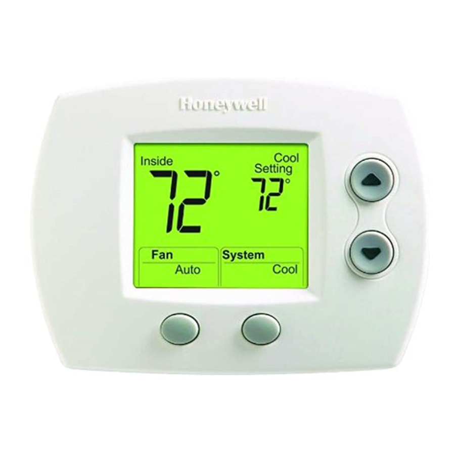
Honeywell TH5110D Installation Instructions Manual
Non-programmable thermostat
Hide thumbs
Also See for TH5110D:
- Installation manual (17 pages) ,
- Operating manual (60 pages) ,
- Operating instructions manual (28 pages)
Table of Contents
Advertisement
APPLICATION
The TH5110D Non-programmable Thermostat provides
electronic control of 24 Vac, single-stage heating and
Feature
Powering Methods
System Types (Up to 1 Heat, 1 Cool)
Changeover
System Setting
Fan Setting
MERCURY NOTICE
If this control is replacing a control that contains
mercury in a sealed tube, do not place your old
control in the trash.
Contact your local waste management authority
for instructions regarding recycling and the
proper disposal of the old thermostat.
® U.S. Registered Trademark
Copyright © 2004 Honeywell International Inc. •
TH5110D Non-programmable
Table 1. TH5110D Thermostat description.
• Battery only
• Common wire only
• Common wire with battery backup
• Gas, oil or electric heat with air conditioning
• Warm air, hot water, high efficiency furnaces, heat pumps, steam
and gravity
• Heat only— includes power to open and power to close zone valves
(Series 20) and normally-open zone valves
• Heat only with fan
• Cool only
• 750 mV heating systems
Manual or auto changeover selectable
Heat-Off-Cool-Auto
Auto-On
• All Rights Reserved
INSTALLATION INSTRUCTIONS
cooling systems or 750 mV heating systems. See Table 1
for a description.
Description
Thermostat
69-1712—1
Advertisement
Table of Contents

Summary of Contents for Honeywell TH5110D
- Page 1 Contact your local waste management authority for instructions regarding recycling and the proper disposal of the old thermostat. ® U.S. Registered Trademark Copyright © 2004 Honeywell International Inc. • TH5110D Non-programmable cooling systems or 750 mV heating systems. See Table 1 for a description.
-
Page 2: Installation
5 FEET [1.5 METERS] Fig. 1. Select thermostat location. Do not install the thermostat where it can be affected by: — Drafts or dead spots behind doors and in corners. — Hot or cold air from ducts. — Radiant heat from sun or appliances. -
Page 3: Wiring
Rc and R. Common wire is optional when thermostat is used with batteries. If thermostat is configured for a heat pump in the Installer Setup, configure changeover valve for cool (O-factory setting) or heat (B). -
Page 4: Wiring Diagrams
TH5110D NON-PROGRAMMABLE THERMOSTAT WIRING DIAGRAMS THERMOSTAT WIRING TERMINALS O/B W HEAT RELAY COMPRESSOR RELAY CONTACTOR POWER SUPPLY. PROVIDE DISCONNECT MEANS AND OVERLOAD PROTECTION AS REQUIRED. FACTORY INSTALLED JUMPER. OPTIONAL 24 VAC COMMON CONNECTION. Fig. 6. Typical hookup of conventional 1H/1C system with one transformer. - Page 5 OPTIONAL 24 VAC COMMON CONNECTION. CONFIGURE SYSTEM TYPE TO HEAT ONLY IN THE INSTALLER SETUP. Fig. 11. Typical hookup of heat only Series 20 system. TH5110D NON-PROGRAMMABLE THERMOSTAT O/B W (HOT) POWER SUPPLY. PROVIDE DISCONNECT MEANS AND OVERLOAD PROTECTION AS REQUIRED.
-
Page 6: Power The Thermostat
Rc and R. Installing Batteries Install two AAA alkaline batteries on the back of the thermostat as marked on the battery holder. See Fig. 14. NOTE: After the thermostat is mounted on the wallplate, the thermostat does not require removal from the wallplate to replace the batteries. -
Page 7: Configure Installer Setup
Fig. 17. TH5110D NON-PROGRAMMABLE THERMOSTAT Fig. 17. Configure Installer Setup. 3. See Fig. 18 to review how the thermostat buttons M22079 are used during Installer Setup. See Table 3 for the Installer Setup Numbers and Settings. -
Page 8: Installer Setup Numbers/Settings
TH5110D NON-PROGRAMMABLE THERMOSTAT Installer Setup Numbers and Settings Installer Setup Number Installer Setup Name System Type Changeover Valve-O/B May not appear. Terminal Energized in See Note a Heating or Cooling (Heat Pumps only) Fan Control in Heating May not appear. -
Page 9: How To Use Installer System Test
System Auto Cool Fig. 19. Enter Installer System Test. 2. See Fig. 20 to review how the thermostat buttons are used during the Installer System Test. See Table 4 for available Installer System Tests. System Test Number Press the Next button to go to the beginning of the Installer System Test or press the Done button to exit the Installer System Test. -
Page 10: Thermostat Operation
TH5110D NON-PROGRAMMABLE THERMOSTAT THERMOSTAT OPERATION Thermostat Buttons and Battery Holder See Fig. 21 for description of thermostat buttons and battery holder. BATTERY HOLDER LAT CH DIGITAL DISPLAY PRESS TO RELEASE BATTERY HOLDER FAN BUTTON SELECTS AUTO OR ON SYSTEM BUTTON SELECTS HEAT, OFF, COOL OR AUTO Fig. -
Page 11: Troubleshooting
Setup Number 1) is set to Heat Pump time. (Setting 1). Heating and cooling wires are shorted together. TH5110D NON-PROGRAMMABLE THERMOSTAT Table 5. Troubleshooting Possible Cause Check for 24 Vac between Rc and C. Check that fresh AAA alkaline batteries are installed as marked on the battery holder. -
Page 12: Specifications
TH5110D NON-PROGRAMMABLE THERMOSTAT Symptom Heating equipment is Heating equipment is not a heat pump running in the cool but System Type (Installer Setup mode. Number 1) is set to Heat Pump (Setting 1). Heating equipment does Heating equipment is not a heat pump...


