Table of Contents
Advertisement
Quick Links
Notes: This model's CD mechanism changer unit is CRS1. Please refer to the original Service Manual
(Order No. MD0509368C0) for this mechanism.
Specifications
AMPLIFIER SECTION
RMS output power stereo mode
THD 10%, both channels driven
1 kHz
Total RMS stereo mode power
FM/AM TUNER, TERMINALS SECTION
Preset station
Frequency Modulation (FM)
Frequency range
Antenna terminal(s)
Amplitude Modulation (AM)
Frequency range
Music Port (front) jack
Sensitivity
Terminal
Headphone jack
Terminal
Output impedance
CASSETTE DECK SECTION
Type
Track system
Heads
125 W per channel (3
250 W
FM 25 stations
AM 15 stations
87.50 to 108.00 MHz (50 kHz steps)
75
(unbalanced)
522 to 1629 kHz (9 kHz step)
100 mV, 4.0 k
Stereo, 3.5 mm jack
Stereo, 3.5 mm jack
32
4 track, 2 channel
SA-AK270EB
SA-AK270EG
Colour
(K)... Black Type
Record/playback
Erasure
Motor
)
Recording system
Erase system
Tape speed
Overall frequency response (+3, -6 dB) at DECK OUT
NORMAL
S/N ratio
Wow and flutter
Fast forward and rewind time
DISC SECTION
Disc played [8 cm or 12 cm]
(1) CD-Audio (CD-DA)
(2) CD-R/RW (CD-DA, MP3* formatted disc)
(3) MP3*
* MPEG-1 Layer 3, MPEG-2 Layer 3
Pick up
(Max)
Wavelength
Beam Source
1 way
Audio output (Disc)
Number of channels
© 2008 Matsushita Electric Industrial Co. Ltd.. All
rights
distribution is a violation of law.
ORDER NO. MD0803003CE
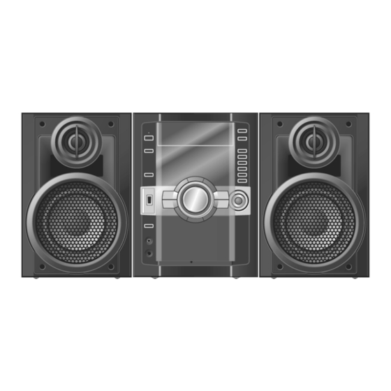
CD Stereo System
Solid permalloy head
Double gap ferrite head
DC servo motor
AC bias 100 kHz
AC erase 100 kHz
35 Hz to 14 kHz
50 dB (A weighted)
0.18 % (WRMS)
Approx. 120 seconds with C-60 cassette tape
Semiconductor laser
reserved.
Unauthorized
copying
4.8 cm/s
780 nm
2 (FL, FR)
and
Advertisement
Table of Contents

Related Manuals for Panasonic SA-AK270EB


Summary of Contents for Panasonic SA-AK270EB
-
Page 1: Specifications
ORDER NO. MD0803003CE CD Stereo System SA-AK270EB SA-AK270EG Colour (K)... Black Type Notes: This model’s CD mechanism changer unit is CRS1. Please refer to the original Service Manual (Order No. MD0509368C0) for this mechanism. Specifications AMPLIFIER SECTION Record/playback Solid permalloy head... -
Page 2: Table Of Contents
SA-AK270EB / SA-AK270EG USB SECTION Operating temperature range 0 to 40°C USB Port Operating humidity range 35% to 80% RH (no condensation) USB Standard USB 2.0 full speed Power consumption in standby 0.4 W mode Media file format support SYSTEM MP3 (*.mp3) -
Page 3: Safety Precautions
SA-AK270EB / SA-AK270EG 1 Safety Precautions 1.1. General Guidelines 1. When servicing, observe the original lead dress. If a short circuit is found, replace all parts which have been overheated or damaged by the short circuit. 2. After servicing, ensure that all the protective devices such as insulation barriers and insulation papers shields are properly installed. -
Page 4: Caution For Ac Mains Lead
SA-AK270EB / SA-AK270EG 1.2. Caution for AC Mains Lead 1.3. Before repair and adjustment Disconnect AC power, discharge AC Capacitors C5700, C5701, C5703, C5704, C5705, C5706 and C5707 through a 10 , 5W... -
Page 5: Protection Circuitry
SA-AK270EB / SA-AK270EG resistor to ground. DO NOT SHORT-CIRCUIT DIRECTLY (with a screwdriver blade, for instance), as this may destroy solid state devices. After repairs are completed, restore power gradually using a variac, to avoid overcurrent. Current consumption at AC 230V - 240V, 50 Hz in NO SIGNAL mode (volume min at CD mode) should be ~ 500mA. -
Page 6: Prevention Of Electro Static Discharge (Esd) To
SA-AK270EB / SA-AK270EG 2 Prevention of Electro Static Discharge (ESD) to Electrostatically Sensitive (ES) Devices Some semiconductor (solid state) devices can be damaged easily by electricity. Such components commonly are called Electrostatically Sensitive (ES) Devices. Examples of typical ES devices are integrated circuits and some field-effect transistors and semiconductor “chip”... -
Page 7: Handling Precautions For Traverse Unit
SA-AK270EB / SA-AK270EG 3 Handling Precautions For Traverse Unit The laser diode in the traverse deck (optical pickup) may break down due to potential difference caused by the static electricity of clothes or our human body. So, be careful of electrostatic breakdown during repair of the traverse deck (optical pickup). - Page 8 SA-AK270EB / SA-AK270EG...
-
Page 9: Precaution Of Laser Diode
SA-AK270EB / SA-AK270EG 4 Precaution of Laser Diode Caution : This product utilizes a laser diode with the unit turned "ON", invisible laser radiation is emitted from the pick up lens. Wavelength : 780 nm Maximum output radiation power from pick up : 100 µW/VDE Laser radiation from pick up unit is safety level, but be sure the followings: 1. -
Page 10: About Lead Free Solder (Pbf)
SA-AK270EB / SA-AK270EG 5 About Lead Free Solder (PbF) 5.1. Service caution based on legal restrictions 5.1.1. General description about Lead Free Solder (PbF) The lead free solder has been used in the mounting process of all electrical components on the printed circuit boards used for this equipment in considering the globally environmental conservation. -
Page 11: Operation Procedures
SA-AK270EB / SA-AK270EG 6 Operation Procedures 6.1. Main Unit Key Buttons Operations... -
Page 12: Remote Control Key Buttons Operations
SA-AK270EB / SA-AK270EG 6.2. Remote Control Key Buttons Operations... - Page 13 SA-AK270EB / SA-AK270EG...
-
Page 14: New Features
SA-AK270EB / SA-AK270EG 7 New Features 7.1. Using the Music Port This feature enables you to enjoy music from a portable audio equipment. - Page 15 SA-AK270EB / SA-AK270EG 7.2. Connecting and Playing a USB Mass Storage Class Device...
-
Page 16: Self Diagnosis And Special Mode Setting
SA-AK270EB / SA-AK270EG 8 Self diagnosis and special mode setting This unit is equipped with functions for checking and inspecting namely: Self-Diagnostic and Test Mode. 8.1. Service Mode Summary Table The service modes can be activated by pressing various button combination on the main unit and remote control unit. Below is the... -
Page 17: Service Mode Table
SA-AK270EB / SA-AK270EG 8.2. Service Mode Table 1... - Page 18 SA-AK270EB / SA-AK270EG 8.3. Service Mode Table 2...
- Page 19 SA-AK270EB / SA-AK270EG 8.4. Reliability Test Mode (CRS1 Mechanism) Below is the process flow chart of ageing for the Mechanism unit. (CRS1)
-
Page 20: Error Code Table Display
SA-AK270EB / SA-AK270EG 8.5. Error code Table Display Self-Diagnosis Function (refer Section “8.2 Service Mode Table 1”) provides information on any problems occuring for the unit and its respective components by displaying the error codes. These error code such as U**, H** and F** are stored in memory and held... - Page 21 SA-AK270EB / SA-AK270EG The error code is automatically display after entering into self-diagnostic mode. 8.5.1. Error Code Table (For Deck Mechanism)
- Page 22 SA-AK270EB / SA-AK270EG 8.5.2. Error Code Table (For CD Changer)
-
Page 23: System
SA-AK270EB / SA-AK270EG 8.5.3. Error Code Table (For Power Supply) 8.5.4. CRS1 Error Code display CRS1 Error Code display 1. The errors that occured in CRS1 Mechanism can be recalled and displayed, in the order of the occurence under self-diagnostic for procedures to enter this mode. - Page 24 SA-AK270EB / SA-AK270EG 3. To clear the error code memory In CRS1 Self-Diagnostic mode, long press [DISC EXCHANGE] key (2s or more) 4. To exit CRS1 Self Diagnostic mode, turn off the set.
-
Page 25: Assembling And Disassembling
SA-AK270EB / SA-AK270EG 9 Assembling and Disassembling 9.1. Caution Special Note: This model uses a new Mechanism unit (CRS1). In this following section does not contain the necessary disassembly & assembly information for the Mechanism unit (CRS1) except the disassembly & assembly of traverse unit. Kindly refer to the original service manual for the Mechanism unit. - Page 26 SA-AK270EB / SA-AK270EG...
-
Page 27: Disassembly Flow Chart
SA-AK270EB / SA-AK270EG 9.2. Disassembly flow chart The following chart is the procedure for disassembling the casing and inside parts for internal inspection when carrying out the servicing. To assemble the unit, reverse the steps shown in the chart as below. - Page 28 SA-AK270EB / SA-AK270EG 9.3. Main Components and P.C.B. Location...
-
Page 29: Disassembly Of Top Cabinet
SA-AK270EB / SA-AK270EG release the catches. 9.4. Disassembly of Top Cabinet Step 1 Remove 3 screws on both sides of the top cabinet. Step 2 Remove 5 screws at the rear panel. Step 5 Lift up the top cabinet and remove it in the direction of arrow. - Page 30 SA-AK270EB / SA-AK270EG Step 2 Detach the FFC cables at connectors (CN2801 & Special Note: During reassembling procedure, ensure both the CN2805) at Main P.C.B.. claws and catches are fully catched. Assembly is secured upon hearing a click sound. Step 5 Release the tabs at the bottom of the front panel.
-
Page 31: Disassembly Of Rear Panel
SA-AK270EB / SA-AK270EG Note: For disassembly & assembly of traverse unit, please Step 7 Lift up the Mechanism Unit (CRS1). refer to original Service Manual for the Disassembly and Assembly of the Mechanism Unit (CRS1). 9.6. Disassembly of Rear Panel Follow the (Step 1) - (Step 5) of Item 9.4... -
Page 32: Disassembly Of Front Panel
SA-AK270EB / SA-AK270EG P.C.B.. Step 5 Detach 22P FFC cable at connector (CN2011) at Main P.C.B.. Step 3 Release 2 catches from the side panel. Step 4 Remove the rear panel as arrow shown. Step 6 Remove the front panel unit. - Page 33 SA-AK270EB / SA-AK270EG 9.8. Disassembly of Panel P.C.B., Tact Switch P.C.B. & Remote Sensor P.C.B. Follow the (Step 1) - (Step 5) of Item 9.4 Follow the (Step 3) - (Step 5) of Item 9.5 Follow the (Step 1) - (Step 6) of Item 9.7 Step 1 Remove Volume knob as arrow shown.
- Page 34 SA-AK270EB / SA-AK270EG Step 6 Release 2 catches at Sensor P.C.B.. Caution Notes: 1. During assembling of the P.C.B.s, ensure that the diode shown on Tact Switch P.C.B. are in upright position. 2. During reassembling procedures, ensure that D-Bass knob is seated properly.
- Page 35 SA-AK270EB / SA-AK270EG 9.10. Disassembly of Music Port P.C.B. Step 2 Use a screwdriver to release the catches at both side of the USB unit. Follow the (Step 1) - (Step 5) of Item 9.4 Follow the (Step 3) - (Step 5) of Item 9.5 Follow the (Step 1) - (Step 6) of Item 9.7...
-
Page 36: Disassembly Of Cd Lid
SA-AK270EB / SA-AK270EG Note: Please ensure that the spring is assembly at right position. 9.12. Disassembly of Deck Mechanism Unit Follow the (Step 1) - (Step 5) of Item 9.4 Follow the (Step 3) - (Step 5) of Item 9.5 Follow the (Step 1) - (Step 6) of Item 9.7... - Page 37 SA-AK270EB / SA-AK270EG Step 2 Desolder 2P wires at the motor terminal. Step 3 Detach 9P cable at connector (CP1902) on Deck P.C.B.. Step 3 Remove the deck mechanism unit as arrow shown. Step 4 Detach connector CP1301 from the Head connector.
- Page 38 SA-AK270EB / SA-AK270EG Follow the (Step 1) - (Step 6) of Item 9.7 Follow the (Step 1) - (Step 3) of Item 9.12 Follow the (Step 1) - (Step 4) of Item 9.14 9.14.1. Replacement of Pinch Roller and Head Block Step 1 Release catch to remove the pinch roller (F) Assy.
- Page 39 SA-AK270EB / SA-AK270EG...
-
Page 40: Disassembly Of Cassette Lid
SA-AK270EB / SA-AK270EG 9.16. Disassembly of Cassette Lid 9.15. Disassembly of Deck Follow the (Step 1) - (Step 5) of Item 9.4 Follow the (Step 3) - (Step 5) of Item 9.5 Mechanism P.C.B. Follow the (Step 1) - (Step 6) of Item 9.7 Follow the (Step 1) - (Step 5) of Item 9.4... -
Page 41: Disassembly Of Traverse Unit
SA-AK270EB / SA-AK270EG Important notes: Ensure all the trays are in the “STOCK” position before proceeding to the disassemble of traverse unit. For procedures to set the trays in “STOCK” position, please refer to (5.3 Setting the Tray In “STOCK” position for CRS1 Service Manual order no. - Page 42 SA-AK270EB / SA-AK270EG Step 1: Turn over the unit and install the traverse unit. Step 2: Push the traverse slide plate as arrow shown to release the traverse unit. Caution: Do not exert strong force on the traverse slide plate.
- Page 43 SA-AK270EB / SA-AK270EG Step 4 Remove 4 screws at the rear panel. Step 2 Detach 8P wire connector (CN5500) at D-Amp P.C.B.. Step 5 Lift up the D-Amp P.C.B. together with the chassis support as arrow shown. Step 3 Remove 2 screws at D-Amp P.C.B. chassis support .
- Page 44 SA-AK270EB / SA-AK270EG 9.20. Replacement of Digital Amp IC (IC5000) Follow the (Step 1) - (Step 5) of Item 9.4 Follow the (Step 1) - (Step 7) of Item 9.5 Follow the (Step 1) - (Step 7) of Item 9.19 Step 1 Flip over D-Amp P.C.B..
- Page 45 SA-AK270EB / SA-AK270EG Make sure it is well tighten to prevent overheat. Note: Use a blower to remove the minute particles that might caused left on the TR Spring. Step 6 Detach 11P wires cable at connector (CN5802) at SMPS P.C.B..
- Page 46 SA-AK270EB / SA-AK270EG Step 8 Remove 1 screw at rear panel. Step 2 Remove 1 screw form the Main P.C.B.. Step 3 Remove the Voltage Regulator IC (IC2731) from the heat sink. Caution: Handle the heat sink with caution due to its high temperature after prolonged use.
- Page 47 SA-AK270EB / SA-AK270EG Step 2 Remove 4 screws at SMPS P.C.B.. Step 3 Remove the Switch (Q2751) from the heat sink. Caution: Handle the heat sink with caution due to its high temperature after prolonged use. Touching it may lead to injuries.
- Page 48 SA-AK270EB / SA-AK270EG Note : Refer to the diagrams of SMPS P.C.B. (Item 19.6.) for location of the part. 9.25. Replacement of Switch Regulator IC (IC5701) 9.25.1. Assembly of Switch Regulator IC Follow the (Step 1) - (Step 5) of Item 9.4 (IC5701) Follow the (Step 1) - (Step 7) of Item 9.5...
- Page 49 SA-AK270EB / SA-AK270EG Step 6 Remove the switch regulator diode (D5702) from the heat sink A. Caution: Handle the heat sink A with caution due to its high temperature after prolonged use. Touching it may lead to injuries. Special Note: Ensure pins of the switch regulator IC (IC5701) are properly seated and soldered on SMPS P.C.B..
- Page 50 SA-AK270EB / SA-AK270EG Note: Refer to the diagrams of SMPS P.C.B. (Item 19.6.) for location of the part. 9.27.1. Assembly of Regulator Diode (D5801) Step 1 Apply grease to the heat sink unit C. Special Note: Ensure pins of the switch regulator diode Step 2 Fix and screw the regulator diode (D5801) to the heat (D5702) are properly seated and soldered on SMPS P.C.B..
- Page 51 SA-AK270EB / SA-AK270EG Special Note: Ensure pins of the regulator diode (D5801) are screwed to the heat sink unit C. properly seated and soldered on SMPS P.C.B.. 9.28. Replacement of Regulator Diode (D5802) Follow the (Step 1) - (Step 5) of Item 9.4 Follow the (Step 1) - (Step 7) of Item 9.5...
- Page 52 SA-AK270EB / SA-AK270EG Step 2 Remove 1 screw from the regulator diode (D5803). Step 3 Remove the regulator diode (D5803) from the heat sink unit C. Caution: Handle the heat sink unit C with caution due to its high temperature after prolonged use. Touching it may lead to injuries.
- Page 53 SA-AK270EB / SA-AK270EG between AC Inlet P.C.B. to the chassis. Note: During reassembling procedures, ensure the P.C.B. is seated properly at the locators. Step 4 Detach the rear panel slightly backward as arrow shown. Step 5 Lift up the AC Inlet P.C.B..
-
Page 54: Service Fixture And Tools
SA-AK270EB / SA-AK270EG 10 Service Fixture and Tools Service Tools Extension FFC (A) Main P.C.B. (CN2341) - D-Amp P.C.B. (CN5050) REEX0930 (17P FFC Wires) (B) Main P.C.B. (CN2701) - SMPS P.C.B. (CN5802) REXX0680 (11P Wires) (C) SMPS P.C.B. (H5801) - D-Amp P.C.B. (CN5500) - Page 55 SA-AK270EB / SA-AK270EG Step 9 Remove 4 screws at the Deck Mechanism unit. Step 12 Connect 27P FFC cable at connector (CN2806) at Main P.C.B.. Step 13 Connect 21P FFC cable at connector (CN3200) at Main P.C.B.. Step 14 Connect 10P FFC cable at connector (CN2807) at Main P.C.B..
- Page 56 SA-AK270EB / SA-AK270EG Step 17 Check and repair Panel P.C.B., Deck P.C.B., Tact Switch P.C.B., and Music port P.C.B.. 11.3. Checking and Repairing of D- Amp P.C.B. Follow (Step 1) - (Step 2) of item 11.2 Step 1 Detach 17P FFC cable at connector (CN5050) at D- Amp P.C.B..
- Page 57 SA-AK270EB / SA-AK270EG Step 10 Attach original cable with extension cable (REXX0683) (8P cable from H5801 to CN5500). Step 11 Connect extension cable (REEX0930) (17P cable from CN2341 to CN5050). Step 6 Remove 3 screws from D-Amp P.C.B.. Step 7 Lift up D-Amp P.C.B. as arrow shown.
- Page 58 SA-AK270EB / SA-AK270EG Step 5 Remove 1 screw at the rear panel. Step 2 Remove 4 screws. Step 6 Move the rear panel slightly backward as arrow shown, lift up the AC Inlet P.C.B. together with the SMPS P.C.B.. Step 3 Remove 2 screws at AC Inlet P.C.B..
- Page 59 SA-AK270EB / SA-AK270EG Step 7 Position SMPS P.C.B. & AC Inlet P.C.B. according to the diagram shown. Step 8 Connect 22P cable at the connector (CN2801) on Main P.C.B.. Step 9 Connect 14P cable at the connector (CN2805) on Main P.C.B..
- Page 60 SA-AK270EB / SA-AK270EG Step 13 Service AC Inlet P.C.B. & SMPS P.C.B. respectively.
-
Page 61: Procedure For Checking Operation Of Individual Parts Of Deck Mechanism Unit
SA-AK270EB / SA-AK270EG 12 Procedure for Checking Operation of Individual Parts of Deck Mechanism Unit 12.1. Operation Check with Cassette Tape 1. Pull up the EJECT lever using a rubber band. (Fig. 6) 2. Supply DC5V to MOTOR. ( MOTOR rotates.) (Fig. 5) 3. -
Page 62: Measurement And Adjustments
SA-AK270EB / SA-AK270EG 13 Measurement And Adjustments 13.1. Cassette Deck Section 13.1.1. Requirements Test tape (QZZCFM) (QZZCWAT) Normal blank cassette tape (QZZCRA) Digital frequency counter Oscilloscope Electrical voltmeter Headphone jack output jig (Fig 8) 13.1.2. Setting of Unit VOLUME: MAX 13.1.3. - Page 63 SA-AK270EB / SA-AK270EG (Product reference value: 3,000±90Hz) 1. Connect a frequency indicator. (Fig 10) 2. Playback the middle portion of the test tape (QZZCWAT). 3. Adjust the motor screw so that the following output level is produced. (Fig 11) Adjustment Range: 3,000 ± 90Hz (a constant speed) Fig.
-
Page 64: Voltage Measurement And Waveform Chart
SA-AK270EB / SA-AK270EG 14 Voltage Measurement and Waveform Chart Note: Circuit voltage and waveform described herein shall be regarded as reference information when probing defect point, because it may differ from an actual measuring value due to difference of Measuring instrument and its measuring condition and product itself. - Page 65 SA-AK270EB / SA-AK270EG 14.1.2. Main P.C.B.
- Page 66 SA-AK270EB / SA-AK270EG 14.1.3. SMPS P.C.B., D-Amp P.C.B. & Panel P.C.B.
- Page 67 SA-AK270EB / SA-AK270EG 14.1.4. Deck P.C.B., Deck Mechanism P.C.B. & USB P.C.B.
-
Page 68: Waveform Chart
SA-AK270EB / SA-AK270EG 14.2. Waveform Chart... -
Page 69: Wiring Connection Diagram
SA-AK270EB / SA-AK270EG 15 Wiring Connection Diagram... - Page 70 SA-AK270EB / SA-AK270EG...
-
Page 71: Block Diagram
SA-AK270EB / SA-AK270EG 16 Block Diagram 16.1. CD Servo Diagram... - Page 72 SA-AK270EB / SA-AK270EG 16.2. Main Diagram...
- Page 73 SA-AK270EB / SA-AK270EG...
- Page 74 SA-AK270EB / SA-AK270EG 16.3. Panel, Remote Sensor, Music Port, Headphone & Tact Switch Diagram...
- Page 75 SA-AK270EB / SA-AK270EG 16.4. D-Amp Diagram...
- Page 76 SA-AK270EB / SA-AK270EG 16.5. SMPS & AC Inlet Diagram...
- Page 77 SA-AK270EB / SA-AK270EG 16.6. Deck, Deck Mechanism & USB Diagram...
- Page 78 SA-AK270EB / SA-AK270EG...
-
Page 79: Notes Of Schematic Diagram
SA-AK270EB / SA-AK270EG 17 Notes Of Schematic Diagram (All schematic diagrams may be modified at any time with * FOR INDICATION ONLY. the development of new technology) Voltage and Signal lines: Notes: : +B Signal line S971: Mode switch. : -B Signal line S972: Half switch. - Page 80 SA-AK270EB / SA-AK270EG...
-
Page 81: Schematic Diagram
SA-AK270EB / SA-AK270EG 18 Schematic Diagram 18.1. (A) CD Servo Circuit... - Page 82 SA-AK270EB / SA-AK270EG 18.2. (B) Main Circuit...
- Page 83 SA-AK270EB / SA-AK270EG...
- Page 84 SA-AK270EB / SA-AK270EG...
- Page 85 SA-AK270EB / SA-AK270EG...
- Page 86 SA-AK270EB / SA-AK270EG 18.3. (C) Panel Circuit...
- Page 87 SA-AK270EB / SA-AK270EG 18.4. (D) Tact Switch Circuit, (E) Music Port Circuit & (F) Remote Sensor Circuit...
- Page 88 SA-AK270EB / SA-AK270EG 18.5. (G) Deck Circuit...
- Page 89 SA-AK270EB / SA-AK270EG 18.6. (H) Deck Mechanism Circuit & (L) AC Inlet Circuit...
- Page 90 SA-AK270EB / SA-AK270EG 18.7. (I) USB Circuit...
- Page 91 SA-AK270EB / SA-AK270EG 18.8. (J) D-Amp Circuit...
- Page 92 SA-AK270EB / SA-AK270EG...
- Page 93 SA-AK270EB / SA-AK270EG 18.9. (K) SMPS Circuit...
- Page 94 SA-AK270EB / SA-AK270EG...
-
Page 95: Printed Circuit Board
SA-AK270EB / SA-AK270EG 19 Printed Circuit Board Note: Circuit board diagrams may be modified at any time with the development of new technology. - Page 96 SA-AK270EB / SA-AK270EG 19.1. (A) CD Servo P.C.B. & (I) USB P.C.B.
- Page 97 SA-AK270EB / SA-AK270EG 19.2. (B) Main P.C.B. & (E) Music Port P.C.B.
- Page 98 SA-AK270EB / SA-AK270EG 19.3. (C) Panel P.C.B., (D) Tact Switch P.C.B. & (F) Remote Sensor P.C.B.
- Page 99 SA-AK270EB / SA-AK270EG 19.4. (G) Deck P.C.B., (H) Deck Mechanism P.C.B. & (L) AC Inlet P.C.B.
- Page 100 SA-AK270EB / SA-AK270EG 19.5. (J) D-Amp P.C.B.
- Page 101 SA-AK270EB / SA-AK270EG 19.6. (K) SMPS P.C.B.
- Page 102 SA-AK270EB / SA-AK270EG...
-
Page 103: Illustration Of Ics, Transistors And Diodes
SA-AK270EB / SA-AK270EG 20 Illustration of ICs, Transistors and Diodes... -
Page 104: Terminal Function Of Integrated Circuits
SA-AK270EB / SA-AK270EG 21 Terminal Function of Integrated Circuits 21.1. IC2801 (RFKWAK270PL) Pin No. Mark Function BASS_JOG2 Bass Jog 2 System Microprocessor VERR verify error for USB version up using CD Pin No. Mark Function MMOD0 Micon mode switching for USB... - Page 105 SA-AK270EB / SA-AK270EG Pin No. Mark Function Key Data Input 1 (No Connection) Key Data Input 1 (No Connection) Supply Voltage, Negative Terminal Power Supply (+5V) Segment Output 18 Segment Output 17 Segment Output 16 Segment Output 15 Segment Output 14...
- Page 106 SA-AK270EB / SA-AK270EG...
-
Page 107: Exploded Views
SA-AK270EB / SA-AK270EG 22 Exploded Views 22.1. Cabinet Parts Location... - Page 108 SA-AK270EB / SA-AK270EG...
- Page 109 SA-AK270EB / SA-AK270EG 22.2. Deck Mechanism Parts Locations (RAA4407-S)
- Page 110 SA-AK270EB / SA-AK270EG 22.3. Packaging...
-
Page 111: Replacement Parts List
SA-AK270EB / SA-AK270EG 23 Replacement Parts List Notes: Important safety notice: Components identified by mark have special characteristics important for safety. Furthermore, special parts which have purposes of fire-retardent (resistors), high-quality sound (capacitors), low noise (resistors), etc are used. When replacing any of these components, be sure to use only manufacturer’s specified parts shown in the parts list. - Page 112 SA-AK270EB / SA-AK270EG Ref. No. Part No. Part Name & Description Remarks Ref. No. Part No. Part Name & Description Remarks RMB0403 HEAD PANEL SPRING RQTV0277-D O/I BOOK (Ge/Fr/It) [M] EG RMB0404 BRAKE ROD SPRING RQTV0278-H O/I BOOK (Da/Sw/Du) [M] EG...
- Page 113 SA-AK270EB / SA-AK270EG Ref. No. Part No. Part Name & Description Remarks Ref. No. Part No. Part Name & Description Remarks Q5860 2SA207700L TRANSISTOR VR6630 K9AA024A0008 VOLUME ENCODER Q5861 B1ABCF000176 TRANSISTOR Q5862 B1ABCF000176 TRANSISTOR SWITCHES Q5898 B1ABCF000176 TRANSISTOR Q6511 B1GBCFJN0033...
- Page 114 SA-AK270EB / SA-AK270EG Ref. No. Part No. Part Name & Description Remarks Ref. No. Part No. Part Name & Description Remarks L6802 J0JBC0000019 INDUCTOR P5701 K2AA2B000017 AC INLET L6811 J0JBC0000019 INDUCTOR L6812 J0JBC0000019 INDUCTOR EARTH TERMINALS L6851 J0JBC0000019 INDUCTOR L6863...
- Page 115 SA-AK270EB / SA-AK270EG Ref. No. Part No. Part Name & Description Remarks Ref. No. Part No. Part Name & Description Remarks W7011 D0GBR00JA008 0 1/16W R1328 D0GB153JA008 15K 1/16W W7012 D0GBR00JA008 0 1/16W R1329 D0GB472JA008 4.7K 1/16W W7013 D0GBR00JA008 0 1/16W...
- Page 116 SA-AK270EB / SA-AK270EG Ref. No. Part No. Part Name & Description Remarks Ref. No. Part No. Part Name & Description Remarks R2357 D0GB180JA008 18 1/16W R2821 D0GB101JA008 100 1/16W R2358 D0GB180JA008 18 1/16W R2822 D0GB101JA008 100 1/16W R2359 D0GD332JA017 3.3K 1/10W...
- Page 117 SA-AK270EB / SA-AK270EG Ref. No. Part No. Part Name & Description Remarks Ref. No. Part No. Part Name & Description Remarks R5006 D0GZ220JA012 22 1W R5832 ERJ1TYJ222U 2.2K 1W R5007 D0GZ220JA012 22 1W R5834 ERJ1TYJ222U 2.2K 1W R5008 ERJ3GEYJ101V 100 1/10W...
- Page 118 SA-AK270EB / SA-AK270EG Ref. No. Part No. Part Name & Description Remarks Ref. No. Part No. Part Name & Description Remarks R7329 D0GB102JA008 1K 1/16W C1314 F1H1H222A013 2200pF 50V R7330 ERJ3GEYJ562V 5.6K 1/10W C1315 F1H1H222A013 2200pF 50V R7331 D0GB223JA008 22K 1/16W...
- Page 119 SA-AK270EB / SA-AK270EG Ref. No. Part No. Part Name & Description Remarks Ref. No. Part No. Part Name & Description Remarks C2703 EEUFC0J821B 820uF 6.3V C5021 ECJ1VB1H104K 0.1uF 50V C2704 F1H1H103A219 0.01uF 50V C5022 ECJ1VB1H104K 0.1uF 50V C2705 F1H1H101A720 100pF 50V...
- Page 120 SA-AK270EB / SA-AK270EG Ref. No. Part No. Part Name & Description Remarks Ref. No. Part No. Part Name & Description Remarks C5804 F1J2E1030004 0.01uF 250V C7216 ECJ1VB1H681K 680pF 50V C5805 F2B1V222A007 2200uF 35V C7217 ECJ1VB1C104K 0.1uF 16V C5808 F2B1V222A007 2200uF 35V...