Table of Contents
Advertisement
Advertisement
Table of Contents
Troubleshooting

Related Manuals for Samsung Digimax S500


Summary of Contents for Samsung Digimax S500
-
Page 2: Table Of Contents
C O N T E N T S Ⅰ. SPECIFICATION 1. CAMERA SPECIFICATION ……………………………………………………………………………………… 4 2. SYSTEM REQUIREMENTS …………………………………………………………………………………… 5 3. TFT LCD PANEL MARK ……………………………………………………………………………………… 6 4. CONNECTION DIAGRAM ……………………………………………………………………………………… 8 5. IDENTIFICATION OF FEATURES ……………………………………………………………………………… 9 Ⅱ. INSTALLATION & FAQ ………………………………………………………………………………………... - Page 3 2. CIRCUIT DIAGRAM 1) MAIN_BLOCK_S500 ………………………………………………………………………………………63 2) MAIN_DSP_S500 …………………………………………………………………………………………64 3) MAIN_DDR_S500 …………………………………………………………………………………………65 4) MAIN_FEB_S500 …………………………………………………………………………………………66 5) MAIN_MEMORY_S500 ……………………………………………………………………………………67 6) MAIN_MOTOR_S500………………………………………………………………………………………68 7) POWER_S500 ………………………………………………………………………………………………69 8) TOP_S500 …………………………………………………………………………………………………70 9) STROBO_S500 ……………………………………………………………………………………………71 10) STROBO_S500 ……………………………………………………………………………………………72 11) CCD_S500 …………………………………………………………………………………………………73 12) KEY_S500 …………………………………………………………………………………………………74 13) AUDIO_S500 ………………………………………………………………………………………………75 14) LCD_S500 …………………………………………………………………………………………………76 15) CRADLE_S500 ……………………………………………………………………………………………77 16) MAIN_BLOCK_S600 ……………………………………………………………………………………78...
-
Page 4: Ⅰ. Specification
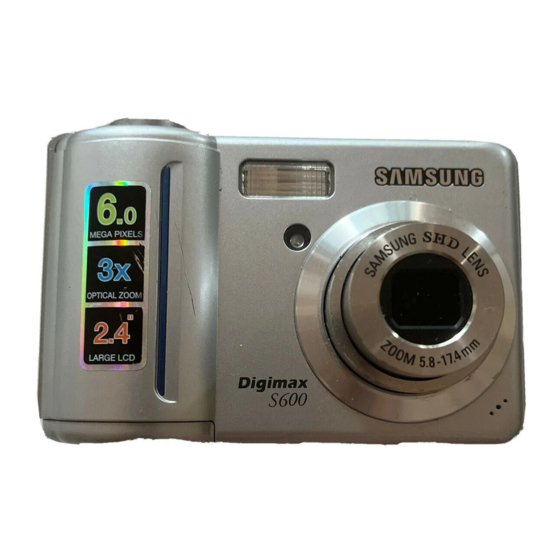
Ⅰ. SPECIFICATION 1. CAMERA SPECIFICATION ■ Image Sensor - Type : 1/2.5" CCD S500 S600 Effective Pixel Approx. 5.1 Mega-pixel Approx. 6.0 Mega-pixel Total Pixel Approx. 5.3 Mega-pixel Approx. 6.1 Mega-pixel ■ Lens - Focal Length : SHD Lens f = 5.8 ~ 17.4mm (35mm film equivalent : 35 ~ 105mm) - F No. -
Page 5: System Requirements
- Capacity (20 MB) Super Fine Fine Normal ※ These figures are measured under Samsung’ s standard conditions and may vary depending on shooting conditions and camera settings ■ Image Play - Type : Single image, Thumbnails, Slide show, Movie Clip - Editing : Trimming, Resizing, Rotate, Effect ■... -
Page 6: Tft Lcd Panel Mark
Ⅰ. SPECIFICATION 3. TFT LCD PANEL MARK ■ Recording mode ① ⑳ ② ⑲ ③ ⑱ ④ ⑰ ⑤ ⑯ ⑥ ⑮ ⑦ ⑭ ⑧ ⑬ ⑨ ⑩ ⑪ ⑫ Descripition Icons Recording mode Battery Aperture Value / Shutter Speed F2.8, 1/30 Continuous shot Flash... - Page 7 Ⅰ. SPECIFICATION Image size Number of available shots remaining Remaining time (Movie clip/ Voice recording) 00:01:30/ 01:00:00 Voice memo Optical/ Digital Zoom bar/ Digital Zoom rate ■ LCD monitor indicator ⑫ ① ② ⑪ ISO : 50 ③ ⑩ Av : F 2.8 ④...
-
Page 8: Connection Diagram
Ⅰ. SPECIFICATION 4. CONNECTION DIAGRAM... -
Page 9: Identification Of Features
Ⅰ. SPECIFICATION 5. IDENTIFICATION OF FEATURES Mode dial Shutter button Power button Strap eyelet Speaker Flash Self-timer lamp / Auto focus lamp Lens / Lens cover Microphone Camera status lamp Zoom W button (Thumbnail) Zoom T button (Digital zoom) E (Effects) button LCD monitor +/- button, Delete button... -
Page 10: Function Button
Ⅰ. SPECIFICATION Bottom Battery chamber cover Memory card slot Battery chamber 5-function button Voice memo / Voice Recording / Up button Menu / OK button Flash / Self-timer / Left button Right button Macro / Down button Play & Pause button... - Page 11 Ⅰ. SPECIFICATION Cradle ● Top Camera connection terminal ● Back USB port / AC connection AV connection terminal terminal...
-
Page 12: Ⅱ. Installation & Faq
Ⅱ. INSTALLATION & FAQ 1. The auto run frame will display. Click the [Install] menu in the Auto run frame. 2. Install the DirectX, Digimax Master by selecting a button shown on the monitor. - Page 13 Ⅱ. INSTALLATION & FAQ...
- Page 14 Ⅱ. INSTALLATION & FAQ...
- Page 15 Ⅱ. INSTALLATION & FAQ 3. After restarting the computer, connect the PC to the camera with the USB cable. 4. Turn the camera power on. The [Found New Hardware Wizard] will open and the computer will recognize the camera. ※ If your OS is Windows XP, an image viewer program will open.
- Page 16 * System Requirements - Windows 98/98SE, ME, 2000, XP (Digimax Master can be installed and run in the Windows 98FE but that is not covered by Samsung's warranty) - Pentium Ⅱ 450MHz or higher (Pentium 700MHz recommended) - Minimum 200MB hard disk space (1GB recommended) - Minimum 64MB RAM (128MB recommended) - 1024X768 pixels, 16-bit colour display compatible monitor.
- Page 17 Ⅱ. INSTALLATION & FAQ < Note > DirectX is required about 55MB hard disk space. It will take about 22MB hard disk space. It will change settings of applications and registries. You can't remove it as the OS doesn't have uninstall program.
- Page 18 Q5. Removing the USB Mass Storage driver for Windows 98/98SE A5. When you remove the USB drivr files for Windows 98/99SE manually, refer to the following steps. 1) Click [Control Panel → Program Add/Remove] and remove the Digimax S500. (2) Click [Start → Run].
- Page 19 1. Functions (1) AutoDownload : This program will download images captured with Samsung camera automatilcally. - Click [File → Basic settings → Find Option] and then check the "....." option. (2) Viewer : You can view the stored images easily.
-
Page 20: Ⅲ. Exploded View And Parts List
Ⅲ. EXPLODED VIEW AND PART LIST 1. MAIN ASSEMBLY... -
Page 21: Body Assembly
Ⅲ. EXPLODED VIEW AND PART LIST 2. BODY ASSEMBLY 2-30 2-31 2-23 2-29 2-24 2-27 2-30 2-17 2-25 2-21 2-10 2-28 2-19 2-22 2-20 2-18 2-26 2-14 2-33 2-12 2-15 2-13 2-16 2-11 2-32... -
Page 22: Barrel Assembly
Ⅲ. EXPLODED VIEW AND PART LIST 3. BARREL ASSEMBLY 3-41 3-14 3-42 3-23 3-24 3-40 3-13 3-25 3-12 3-10 3-19 3-124 3-16 3-20 3-15 3-24 3-21 3-17 3-22 3-18 3-26 3-37 3-11 3-36 3-35 3-34 3-32 3-33 3-31 3-28 3-30 3-29 3-38 3-39... -
Page 23: Barrier Assembly
Ⅲ. EXPLODED VIEW AND PART LIST 4. BARRIER ASSEMBLY... -
Page 24: Front Cover Assembly
Ⅲ. EXPLODED VIEW AND PART LIST 5. FRONT COVER ASSEMBLY 5-19 5-18 5-20 5-11 5-12 5-13 5-10 5-14 5-27 5-15 5-23 5-17 5-25 5-16 5-21 5-22 5-24 5-26... -
Page 25: Back Cover Assembly
Ⅲ. EXPLODED VIEW AND PART LIST 6. BACK COVER ASSEMBLY... -
Page 26: Cradle Assembly
Ⅲ. EXPLODED VIEW AND PART LIST 7. CRADLE ASSEMBLY... -
Page 27: Packing Item
Ⅲ. EXPLODED VIEW AND PART LIST 8. PACKING ITEM 8-22 8-19 8-20 8-12 8-17 8-15 8-18 8-21 8-16 8-10 8-12 8-14 8-13... -
Page 37: Ⅳ. Adjustment
Ⅳ. ADJUSTMENT 1. Digital camera service To take a digital camera service (Repair, Tuning and Checking), the following equipments have to be arranged. The sequences for the camera service are as shown. Receiving the camera 1. Receiving the camera When receiving a camera, check whether the accessories are Checking the camera included or not and ask the customer exact problems. - Page 38 Ⅳ. ADJUSTMENT 1) Equipments for checking and inspection To check and inspect the camera malfunction, the following equipments have to be arranged. ⑥ ④ ↓ ③ ② ⑤ → ① ⑦ ⑪ ⑧ ⑨ → ← ⑩ Device Description PC for inspection - Installing a digital camera driver or Checking the removable device - Checking the file transference(upload and download) - Playing back the still image or movie clip...
- Page 39 Ⅳ. ADJUSTMENT 2) Equipments for camera repair To repair the camera, the following equipments have to be arranged. ⑧ ⑩ → ⑬ ④ ⑫ ⑨ ③ ⑥ ⑦ ② ① ⑪ → ⑤ Device Description A set of tools Pincette/ Screwdriver/ Discharger etc. Cleaning paper For cleaning camera lens and camera parts Detergent container...
- Page 40 Ⅳ. ADJUSTMENT 3) Equipments for camera tuning To tune the camera, the following equipments have to be arranged. ⑤ ② ④ ① ⑥ ③ Device Description AE TESTER For tuning AE and STROBE AWB LIGHT For checking and tuning AWB SOURCE BOX COLOR chart For checking AWB and color of images...
- Page 41 - When the cable is inserted, check whether the images play back on the external monitor. Turn on the camera. - Check whether the green LED is blinking, SAMSUNG LOGO is on and the start-up sound sounds. - Check the “L” and “FINE” icon on the LCD monitor.
- Page 42 Ⅳ. ADJUSTMENT Checking item Check point MANUAL focus. - Check whether the icon and counter are displayed on the LCD monitor. Take a movie clip with TELE zoom - Check whether the recording time is displayed and there are a during 10 seconds.
-
Page 43: Adjustment Items By Changed Parts
Ⅳ. ADJUSTMENT 2. Adjustment items by changed parts After changing the electronic parts of Digimax S500/S600, the parts have to be adjusted in accordance withe the adjusted items. The items listed on the table are have to be adjusted after changing. -
Page 44: Adjustment
Ⅳ. ADJUSTMENT 3. Adjustment To adjust all items, all kinds of code by items have to be inserted in program file and saved them to the SD card as TXT file type. The codes are listed below. < Description of TXT file > Codes of program Codes of program <1>... - Page 45 Ⅳ. ADJUSTMENT 1) OB SETTING After changing the MAIN PCB, adjust the black color. < Codes of program > BASIC PROGRAM OB SETTING <1> PROCESS CODE ; <1>18; <2> 65535 ; <2>65535; <3> PROCESS CODE ; <3>18,1; <4> 0 OR 1 ; <4>1;...
- Page 46 Ⅳ. ADJUSTMENT 2) LENS SHADING After changing the MAIN PCB, BARREL and CCD, adjust the brightness gaps between center of the lens and around the lens. < Codes of program > BASIC PROGRAM LENS SHADING <1> PROCESS CODE ; <1>8; <2>...
- Page 47 Ⅳ. ADJUSTMENT 3) BATTERY LEVEL ADJUSTMENT After changing the MAIN PCB, adjust WARNING LEVEL and LOCK LEVEL. < Codes of program > BASIC PROGRAM BATTERY LEVEL ADJUSTMENT <1> PROCESS CODE ; <1>17; <2> 65535 ; <2>65535; <3> PROCESS CODE ; <3>17,3; <4>...
- Page 48 Ⅳ. ADJUSTMENT 4) BACK LASH ADJUSTMENT After changing the MAIN PCB, BARREL and CCD, adjust the BACK LASH. < Codes of program > BASIC PROGRAM BACK LASH <1> PROCESS CODE ; <1>9; <2> 65535 ; <2>65535; <3> PROCESS CODE ; <3>9,0;...
- Page 49 Ⅳ. ADJUSTMENT 5) SHUTTER CLOSE TIME ADJUSTMENT After changing the MAIN PCB, BARREL and CCD, adjust the SHUTTER CLOSE TIME. < Codes of program > BASIC PROGRAM SHUTTER CLOSE TIME <1> PROCESS CODE ; <1>7; <2> 65535 ; <2>65535; <3> PROCESS CODE ; <3>7,1;...
- Page 50 Ⅳ. ADJUSTMENT 6) FLASH ADJUSTMENT After changing the MAIN PCB and SUB PCB, adjust the FLASH. < Codes of program > BASIC PROGRAM FLASH ADJUSTMENT <1> PROCESS CODE ; <1>13; <2> 65535 ; <2>65535; <3> PROCESS CODE ; <3>13,1; <4> 0 OR 1 ; <4>1;...
- Page 51 Ⅳ. ADJUSTMENT 7) PUNT ADJUSTMENT After changing the MAIN PCB and BARREL, adjust the PUNT. < Codes of program > BASIC PROGRAM PUNT ADJUSTMENT <1> PROCESS CODE ; <1>2; <2> 65535 ; <2>65535; <3> PROCESS CODE ; <3>2,3; <4> 0 OR 1 ; <4>1;...
- Page 52 Ⅳ. ADJUSTMENT 8)BURNING TEST & CCD DEFECT CELL After changing the MAIN PCB and parts, check whether all of the camera functions work correctly. After changing the MAIN PCB and CCD, do the BURNING TEST and adjust the DEFECT CELL of CCD. <...
- Page 53 Ⅳ. ADJUSTMENT 9) EEPROM READ To read the data of EEPROM, refer to the below codes. < Codes of program > BASIC PROGRAM EEPROM READ <1> PROCESS CODE ; <1>16; <2> 65535 ; <2>65535; <3> PROCESS CODE ; <3>16,3; <4> 0 OR 1 ; <4>0;...
- Page 54 Ⅳ. ADJUSTMENT 10) EEPROM WRITE If you want to write the DATA of EEPROM, do as follows. < Codes of program > BASIC PROGRAM EEPROM WRITE <1> PROCESS CODE ; <1>17; <2> 65535 ; <2>65535;53248 <3> PROCESS CODE ; <3>17,3; <4>...
-
Page 55: How To Check The Firmware Version
Ⅳ. ADJUSTMENT 4. How to check the FIRMWARE VERSION 1. Remove the SD card from the camera and turn it on. 2. In any camera modes, press the UP button twice to select the Voice recording mode. 3. When the Voice recording mode is displayed on the LCD monitor, press the left, right, down and +.-/Delete button one by another to check the firmware. -
Page 56: How To Update The Firmware
Ⅳ. ADJUSTMENT 5. How to update the FIRMWARE 1. Visit our web site 'www.samsungcamera.com/service' and download the firmware (for S500 download "STS253.elf" and for S600 download "STS263.elf") in the temporary folder. 2. Insert the SD card that has the firmware to the camera and turn on the camera. Then, select the Voice recording mode by doing the same way as firmware version check. -
Page 57: Ⅴ. Pattern Diagram
Ⅴ. PATTERN DIAGRAM 1. PARTS ARRANGEMENT FOR EACH PCB ASS’Y 1) MAIN_TOP... -
Page 58: Main_Bottom
Ⅴ. PATTERN DIAGRAM 2) MAIN_BOTTOM... -
Page 59: Top
Ⅴ. PATTERN DIAGRAM 3) TOP 4) STROBO... -
Page 60: Ccd_Top
Ⅴ. PATTERN DIAGRAM 5) CCD_TOP 6) CCD_BOTTOM... -
Page 61: Ⅵ. Circuit Diagram
Ⅵ. CIRCUIT DIAGRAM 1. BLOCK DIAGRAM... -
Page 62: Circuit Diagram 1) Main_Block_S500
Ⅵ. CIRCUIT DIAGRAM 2. CIRCUIT DIAGRAM 1) MAIN_BLOCK_S500... -
Page 63: Main_Dsp_S500
Ⅵ. CIRCUIT DIAGRAM 2) MAIN_DSP_S500... -
Page 64: Main_Ddr_S500
Ⅵ. CIRCUIT DIAGRAM 3) MAIN_DDR_S500... -
Page 65: Main_Feb_S500
Ⅵ. CIRCUIT DIAGRAM 4) MAIN_FEB_S500... -
Page 66: Main_Memory_S500
Ⅵ. CIRCUIT DIAGRAM 5) MAIN_MEMORY_S500... -
Page 67: Main_Motor_S500
Ⅵ. CIRCUIT DIAGRAM 6) MAIN_MOTOR_S500... -
Page 68: Power_S500
Ⅵ. CIRCUIT DIAGRAM 7) POWER_S500... -
Page 69: Top_S500
Ⅵ. CIRCUIT DIAGRAM 8) TOP_S500... -
Page 70: Strobo_S500
Ⅵ. CIRCUIT DIAGRAM 9) STROBO_S500... -
Page 71: Strobo_S500
Ⅵ. CIRCUIT DIAGRAM 10) STROBO_S500... -
Page 72: Ccd_S500
Ⅵ. CIRCUIT DIAGRAM 11) CCD_S500... - Page 73 Ⅵ. CIRCUIT DIAGRAM _S500...
-
Page 74: Audio_S500
Ⅵ. CIRCUIT DIAGRAM 13) AUDIO_S500... -
Page 75: Lcd_S500
Ⅵ. CIRCUIT DIAGRAM 14) LCD_S500... -
Page 76: Cradle_S500
Ⅵ. CIRCUIT DIAGRAM 15) CRADLE_S500... -
Page 77: Main_Block_S600
Ⅵ. CIRCUIT DIAGRAM 16) MAIN_BLOCK_S600... -
Page 78: Main_Coach_S600
Ⅵ. CIRCUIT DIAGRAM 17) MAIN_COACH_S600... -
Page 79: Main_Ddr_S600
Ⅵ. CIRCUIT DIAGRAM 18) MAIN_DDR_S600... -
Page 80: Main_Fep_S600
Ⅵ. CIRCUIT DIAGRAM 19) MAIN_FEP_S600... -
Page 81: Main_Memory_S600
Ⅵ. CIRCUIT DIAGRAM 20) MAIN_MEMORY_S600... -
Page 82: Main_Motor_S600
Ⅵ. CIRCUIT DIAGRAM 21) MAIN_MOTOR_S600... -
Page 83: Power_S600
Ⅵ. CIRCUIT DIAGRAM 22) POWER_S600... -
Page 84: Top_S600
Ⅵ. CIRCUIT DIAGRAM 23) TOP_S600... -
Page 85: Strobo_S600
Ⅵ. CIRCUIT DIAGRAM 24) STROBO_S600... -
Page 86: Key_S600
Ⅵ. CIRCUIT DIAGRAM 25) KEY_S600... -
Page 87: Audio_S600
Ⅵ. CIRCUIT DIAGRAM 26) AUDIO_S600... - Page 88 Ⅵ. CIRCUIT DIAGRAM _S600...
-
Page 89: Cradle_S600
Ⅵ. CIRCUIT DIAGRAM 28) CRADLE_S600... -
Page 90: Ⅶ. Troubleshooting
Ⅶ. TROUBLESHOOTING 1. Check List for repairing 1) When received · Grasp customer's complaints exactely · Check the product's condition of exterior view(damage by shock) · Check the condition of battery and all kinds of cables(USB cable, AV cable, AC Adaptor) ·... -
Page 91: Main Troubleshooting
Ⅶ. TROUBLESHOOTING 2. Main troubleshooting 1) The power can't be turned on Check : Power input (Battery, Adaptor, etc.) ① Check connection : Between the Main PCB and the TOP F PCB. Check the assembly ② Check soldering : Battery contact condition of various ③... - Page 92 Ⅶ. TROUBLESHOOTING ④ How to upgrade the FULL VERSION FIRMWARE Connect the camera with power supply and turn on the power. If the electricity current consumes between 200 and 330mA and the camera doesn°Øt turn on, recover the flash memory by following instruction.
- Page 93 Ⅶ. TROUBLESHOOTING ⑤ Check the output voltage of TPs You can check the defect of parts by checking the output voltage of TPs on the Main PCB. 1. Location of TPs on the Main Board TP21 TP22...
- Page 94 Ⅶ. TROUBLESHOOTING TP18 TP19 TP10 TP13 TP11 TP20 TP23 TP12 TP14 TP15 TP16 TP17 TP NAME Normal voltage N7±5CCD -7.5 CCD±CNT 3.3V 3±3CCD 3.0V 4±5VCC 5.0V 3±3HR 3.3V CCD±CNT2 3.3V 3±3LCD 3.3V BLEDP 10.5V BLEDN 15CCD 1.5V VCC±MOT 3.3V 3±3AUD 3.3V CCD±CNT3 3.3V...
-
Page 95: Pattern Of Power Pcb
Ⅶ. TROUBLESHOOTING 3. Pattern of Power PCB 1) MAIN PCB(TOP) FUSE 3±3VCC_CCD 3±3VCC_HR... - Page 96 Ⅶ. TROUBLESHOOTING 2) MAIN PCB(BOTTOM) 4±5VCC VCC input part BACKLIGHT 2±5VCC_MAIN 15VCC_CCD U±P1 3±3VCC_MAIN VCC±MOT 1±8VCC_MAIN N7±5VCC_CCD 3±3VCC_AUD BAT±CHK RESET part...
-
Page 97: How To Check Each Parts
Ⅶ. TROUBLESHOOTING 4. How to check each parts Is the voltage of Main PCB 3V? Does the over current Changing Fuse take place? The camera doesn't turn on and the current Does the over current Is the voltage of is between hundreds take place? TP14 3.3V? or thousands of mA. - Page 98 Ⅶ. TROUBLESHOOTING The voltage of The voltage of The voltage of TP 20 is about 1.75V TP 2 is 3.3V TP 12 is 3.3V Change the The voltage of The voltage of TP 13 is 3.3V TP 3 is 3V U±F3 The voltage of Is the voltage of...
- Page 99 Ⅶ. TROUBLESHOOTING 2) Flash Defect. ① Check the XE TUBE condition (Breakage, incorrect assembly) ② Check the connection (soldering) of MAIN PCB ③ Check the IGBT(Q1) ① ④ Check the Tirg Coil(T1) ⑤ Flash F PCB defect ② ③ ④ <...
- Page 100 Ⅶ. TROUBLESHOOTING 3) Flashing Defect. ① Check the connetion (soldering) of MAIN PCB ② Check the Trans (T±S1) on the MAIN PCB ③ Check the charging status of MAIN CONDENSOR ① Check the connetion (soldering) of MAIN PCB ② T±S1 MAIN BOTTOM...
- Page 101 Ⅶ. TROUBLESHOOTING 4) Defect related to the CCD When the camera is connected to the external LCDE related defect monitor, images are displayed correctly ① Check the connection of CCD F PCB (J±F1) 1. Short ② heck the soldering condition of CCD 2.
- Page 102 Ⅶ. TROUBLESHOOTING ③ Check the circuit of CCD on the MAIN PCB J± U± 3_3CCD U±F2 4_5VCC 3_3HR U±F4 3.3V 4.5V OK → 3V NG : Change U_F3 4_5VCC TP :4.5V 4.5V OK → 3.3V NG : Change U_F4 3_3CCD :3V 3_3HR :3.3V C_F29, C_F36, C_F39 :3V C_F44 :3.3V...
- Page 103 Ⅶ. TROUBLESHOOTING 5) Defect related to the LCD When the camera is connected to the external Check the defect of CCD monitor, images are displayed correctly ① Images are not displayed on the LCD - Check the connection Check the connection of LCD F PCB ②...
- Page 104 Ⅶ. TROUBLESHOOTING 6) Defect related to AUDIO - First of all, check that the AUDIO is ON in the MENU. - When the MIC & SPEAKER are soldered, be careful of breakage by a high temperature. Check the soldering condition of speaker Check the connection of Top F PCB and whether the pattern of #12, 13are shorted or not Check the soldering condtion of MIC L/W...
- Page 105 Ⅶ. TROUBLESHOOTING 7) Defect related to the card, cradle or key recognition Defect related to the card recognition → Check the soldering condition of Card socket Defect related to the Cradle → Check the connection to the camera...
-
Page 106: Ⅷ. Service Information
Ⅷ. SERVICE INFORMATION 1. The order of disassembly and assembly ■ Caution 1. Do the disassembling and assembling camera where the blocking static electricity mat is on the table. 2. When handling the major PCBs of camera, please wearing the band which cuts off the electric current on the wrist. - Page 107 Ⅷ. SERVICE INFORMATION ■ The order of disassembly 1. Remove SCREWS. a X 6 b X 2 2. Take apart the BACK COVER. When disassemble the Back cover, take care not to break the connection part.
- Page 108 Ⅷ. SERVICE INFORMATION 3. Remove the screws to disassemble the LCD FRAME. 4. To disassemble the LCD FRAME, remove the Main PCB connector. 5. Disassemble the LCD FRAME and discharge the Main condensor. CAUTION After disassembling the LCD FRAME, you must discharge the Main condensor before doing the next step.
- Page 109 Ⅷ. SERVICE INFORMATION 6. To disassemble the FRONT COVER, remove the MODE F PCB and a screw. a x 1 CAUTION When you disassemble the FRONT COVER, remove the MODE F PCB CONNECTOR first. 7. Disassemble the FRONT COVER. 8. To disassemble the MAIN PCB ASS'Y, remove the MODE F PCB soldering and screws.
- Page 110 Ⅷ. SERVICE INFORMATION 9. To disassemble the MAIN PCB ASS'Y, remove the CCD F PCB and BARREL F PCB. 10. To disassemble the LENS ASS'Y, remove the screws. a x 2 b X 2...
- Page 111 Ⅷ. SERVICE INFORMATION 11. To disassemble the STROBE ASS'Y, remove the screws. a X 1 b X 1...
- Page 112 Ⅷ. SERVICE INFORMATION ■ Disassemble the Barrel 1. Remove the soldering and screws. a X 3 b X 1 2. Disassemble the Lens base. Take care of the F PCB.
- Page 113 Ⅷ. SERVICE INFORMATION After disassembling the barrel 3. To disassemble the barrel, remove the screws that hold the F PCB. d X 1 4. Disassemble the Outer Cam Barrel and Outer Guide Barrel.
- Page 114 Ⅷ. SERVICE INFORMATION 5. Disassemble the Outer Guide Barrel from the Outer Cam Barrel. Rotate the Outer Guide Barrel to the Outer Cam Barrel guide part and Disassemble disassemble it. the Outer Guide Guide part Barrel from the Outer Cam Barrel.
- Page 115 Ⅷ. SERVICE INFORMATION 7. To disassemble the Guide Plate from the Cam Barrel, push inside the three point of the Guide Plate and pull the Guide Plate out of the Cam Barrel. 8. Disassemble the 2nd Lens Ass'y and Shutter Ass'y.
- Page 116 Ⅷ. SERVICE INFORMATION 9. To disassemble the Shutter Ass'y and 2nd Lens Ass'y, remove the F PCB Guide and screw. F PCB Guide When disassemble the F PCB Guide, take care of F PCB the double-stick tape. Guide...
- Page 117 Ⅷ. SERVICE INFORMATION 10. Disassemble the Shutter Ass'y. When disassembling, take care of a tape stuck on the 2nd Lens Ass'y After disassembling 11. To disassemble the Gear and Motor of Lens Base, remove the screws. b X 3 f X 1...
- Page 118 Ⅷ. SERVICE INFORMATION 12. Remove the Photo Interrupter and disassemble the Zoom Cover. Remove the Photo Interrupter Disassemble the Zoom Cover 13. Disassemble the Gear part Zoom Gear D Zoom Gear A Zoom Gear C Zoom Gear B...
- Page 119 Ⅷ. SERVICE INFORMATION 14. Remove two screws and disassemble the Zoom Motor. e X 2 15. To disassemble the AF Guide Holder, remove a screw.
- Page 120 Ⅷ. SERVICE INFORMATION AF Guide Holder 16. To disassemble the 3rd Lens Ass'y, remove the spring and disassemble the 3rd Lens Ass'y. Disassemble the 3rd Lens Ass'y...
- Page 121 Ⅷ. SERVICE INFORMATION 17. To disassemble the AF motor Ass'y, remove the AF Clip Holder, screw and AF Clip. h X 1 Removing the AF clip (Rotate it counter-clockwise)
- Page 122 Ⅷ. SERVICE INFORMATION 18. Remove the F PCB from the Lens Base. Disassemble is complete...
- Page 123 Ⅷ. SERVICE INFORMATION ■ Assembling the barrel 1. Assemble the Shutter Ass'y. Take care of the F PCB. When assembling the parts, F PCB must be attached on the 2nd Lens Ass'y firmly. Attached firmly...
- Page 124 Ⅷ. SERVICE INFORMATION 2. Screw them and attach the Shield Tape. 3. Assemble the F PCB Giude. Take care of the direction. F PCB must be attached to the F PCB Guide firmly. F PCB is attached to the F PCB Guide firmly...
- Page 125 Ⅷ. SERVICE INFORMATION 4. Assemble the 2nd Lens Ass'y and Zoom Ring Ass'y. When assembling, arrange the grooves to view the Barrier Lever. After assembling Arrange the holes of 2nd Lens Ass'y and Zoom Ring Ass'y at the same position 5.
- Page 126 Ⅷ. SERVICE INFORMATION 6. Arrange the boss part of the Outer Guide Barrel and guide part of the Outer Guide at the position shown as alongside and assemble them. Arrange the guide part 7. Assemble the Zoom Ring and the 2nd Lens at the postion as shown Ass'y.
- Page 127 Ⅷ. SERVICE INFORMATION The boss must be upper left side of the ass'y before assembling. After assembling...
- Page 128 Ⅷ. SERVICE INFORMATION 8. Assemble the Outor Cam Barrel and Outer The hole of Outer Guide Guide Barrel. Take care of the positions of screw Barrel must be shown hole of the Outer Cam Barrel and reflector of Outer Guide Barrel. Upper side of the Reflecter Sheet After assembling...
- Page 129 Ⅷ. SERVICE INFORMATION 9. Rotate the Outer Cam Barrel to extract the Outer Guide barrier and screw it. Rotate the Outer Cam Barrel is shown Barrel to the opposite direction to put it in. 10. Assmble it with the Lens Base Ass'y. Take care F PCB must be inner of the F PCB.
- Page 130 Ⅷ. SERVICE INFORMATION assemble it to the Barrier Lever Insert the F PCB in the outer side of the hole 11. After assembling, screw them and solder the F PCB.