Table of Contents
Advertisement
APPLICATION
The T8611G Chronotherm® IV Deluxe Programmable
Heat Pump Thermostats provides electronic control of 24
Vac single-zone heat pump systems.
T8611 Changeover
G
Automatic
Em Heat-Heat-Off-Cool-Auto On-Auto
MERCURY NOTICE
If this control is replacing a control that contains
mercury in a sealed tube, do not place your old
control in the trash. Dispose of properly.
Contact your local waste management authority
for instructions regarding recycling and the
proper disposal of the old control.
INSTALLATION
When Installing this Product...
1. Read these instructions carefully. Failure to follow
the instructions can damage the product or cause
a hazardous condition.
2. Check the ratings given in the instructions and on
the product to make sure the product is suitable for
your application.
3. Installer must be a trained, experienced service
technician.
4. After completing installation, use these instructions
to check out the product operation.
Location
Install the thermostat about 5 ft (1.5m) above the floor in
an area with good air circulation at average temperature.
See Fig. 1.
® U.S. Registered Trademark
Copyright © 2002 Honeywell •
T8611G Chronotherm
Heat Pump Thermostats
Table 1. Description of T8611 Thermostats.
System Selection
• All Rights Reserved
Deluxe Programmable
Refer to Table 1 for a general description of the
thermostat. All T8611 thermostats require a common wire
to supply power.
Fan Selection
System and fan selections are done by keyboard.
Do not install the thermostat where it can be affected by:
— drafts, or dead spots behind doors and in corners.
— hot or cold air from ducts.
— radiant heat from sun or appliances.
— concealed pipes and chimneys.
— unheated (uncooled) areas such as an outside wall
behind the thermostat.
Wallplate Installation
The thermostat can be mounted horizontally on the wall
or on a 2 in. x 4 in. (50.8 mm x 101.6 mm) wiring box.
Position wallplate horizontally on the wall or on a
2 in. x 4 in. (50.8 mm x 101.6 mm) wiring box.
1. Position and level the wallplate (for appearance
only). The thermostat will function correctly even
when not level.
2. Use a pencil to mark the mounting holes. See Fig.
2.
3. Remove the wallplate from the wall and drill two
3/16 inch (76 mm) holes in the wall (if drywall) as
marked. For firmer material such as plaster, drill
two 7/32 inch (5.56 mm) holes. Gently tap anchors
(provided) into the drilled holes until flush with the
wall.
4. Position the wallplate over the holes, pulling wires
through the wiring opening.
5. Loosely insert the mounting screws into the holes.
6. Tighten mounting screws.
INSTALLATION INSTRUCTIONS
Comments
®
IV
69-1406-1
Advertisement
Table of Contents

Related Manuals for Honeywell Chronotherm IV T8611G


Summary of Contents for Honeywell Chronotherm IV T8611G
-
Page 1: Wallplate Installation
4. After completing installation, use these instructions to check out the product operation. Location Install the thermostat about 5 ft (1.5m) above the floor in an area with good air circulation at average temperature. See Fig. 1. ® U.S. Registered Trademark Copyright ©... -
Page 2: Mounting Thermostat
WALL FOR WRAPAROUND INSERTION STRIP 7/16 IN. (11 MM). Mounting Thermostat MOUNTING 1. Engage tabs at the top of the thermostat and wall- HOLES MOUNTING 2. Press lower edge of case to close and latch. SCREWS M15044 NOTE: To remove the thermostat from the wall, first pull prevent drafts from affecting the thermostat. -
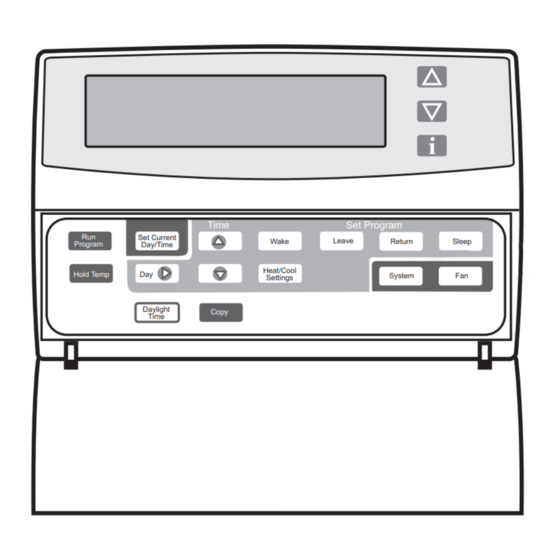
Page 3: Using Thermostat Keys
Auto: Fan operates with equipment. LED Indication Two LED indicators are located in the upper right of the thermostat. They indicate when a Check or Fail signal is sent to the thermostat from the system. See Fig. 8. SET LEAVE TIMES... -
Page 4: Installer Setup
Table 2 and if no changes are necessary, go to the Installer System Test section. The Installer Setup is used to customize the thermostat to specific systems. Some of the options include temperature display, changeover and outdoor temperature display. - Page 5 T8611G CHRONOTHERM Table 3. Thermostat Installer Setup Options. (Continued) Installer Setup Number (Press Time key to Select change) Adaptive Intelligent Recovery™ control. Degree temperature display Not Used. Clock format. Not Used. 17 thru 23 Outdoor temperature display (models with OT terminals).
- Page 6 ® T8611G CHRONOTHERM IV DELUXE PROGRAMMABLE HEAT PUMP THERMOSTATS Table 3. Thermostat Installer Setup Options. (Continued) Installer Setup Number (Press Time key to Select change) Temperature display adjustment. Furnace Air Filter Timer. Humidifier Pad Monitor. Ultraviolet (UV) Air Treatment System Lamp Monitor.
-
Page 7: Setting Current Day And Time
Daylight Copy Time ® IV DELUXE PROGRAMMABLE HEAT PUMP THERMOSTATS INSTALLER SYSTEM-TEST Use the Installer System Test to check the thermostat operation. Refer to Table 4 for a list of the available system-tests. Set Day/Time M14619 To start the sytem-test: Press and hold the increase the same time until 10 appears. - Page 8 ® T8611G CHRONOTHERM IV DELUXE PROGRAMMABLE HEAT PUMP THERMOSTATS Keys to Test Press Number Heating Equipment System-Test Time Enter heating equipment System Test. Stage-one heat comes on. The system fan is also energized. Stage-two heat comes on. Stage-one heat and system fan remain on. Stage-two heat turns off.
-
Page 9: Thermostat Information
T8611G CHRONOTHERM THERMOSTAT INFORMATION 1. Press the Time key to access the thermostat information. 2. Press the increase key to display the production date code. The first two large digits are the month and the third digit is the last digit of the year. -
Page 10: Troubleshooting Guide
— check if the system fuse is blown—replace the fuse. — check if the power switch on the HVAC equipment is in the Off position—set to the On position. — check wiring between thermostat and HVAC equipment—replace any broken wires and tighten any loose connections. - Page 11 Table 6. Troubleshooting Guide. (Continued) Verify operation of heating or cooling equipment in self-test. Enter Installer Setup number 24 and set to 1. Thermostat must have OT terminals and a C7089B1000 installed. Refer to C7089B1000 Installation Instructions and check wiring between the thermostat and sensor.
- Page 12 ® T8611G CHRONOTHERM IV DELUXE PROGRAMMABLE HEAT PUMP THERMOSTATS Automation and Control Solutions Honeywell Honeywell Limited-Honeywell Limitée 1985 Douglas Drive North 35 Dynamic Drive Golden Valley, MN 55422 Scarborough, Ontario M1V 4Z 69-1406—1 G.H. Rev. 12-02 www.honeywell.com/yourhome...