Table of Contents
Advertisement
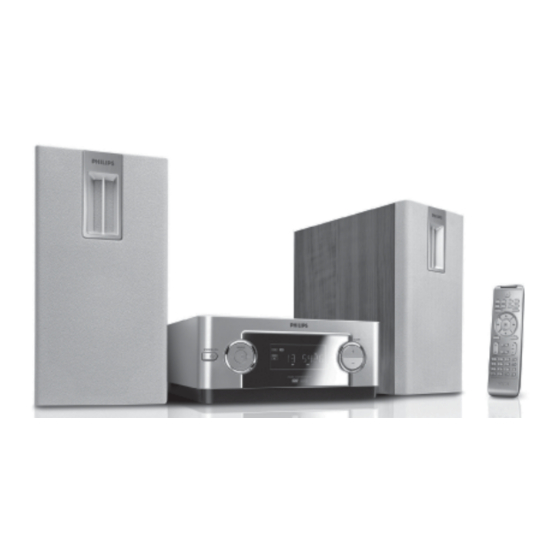
DVD Micro Theatre
©
Copyright 2006 Philips Consumer Electronics B.V. Eindhoven, The Netherlands
All rights reserved. No part of this publication may be reproduced, stored in a retrieval system or
transmitted, in any form or by any means, electronic, mechanical, photocopying, or otherwise without
the prior permission of Philips.
Published by SL 0635 Service Audio
Version 1.1
MCD109
TABLE OF CONTENTS
Location of PC Boards & Versions Variation ........................ 1-2
Specifi cations ....................................................................... 1-3
Measurement Setup ............................................................. 1-4
Service Aids, Safety Instruction, etc ...........................1-5 to 1-7
Connections & Functional Overview......................... 1-8 to 1-11
Troubleshooting ......................................................1-12 to 1-13
Repair Instructions................................................................... 2
Disassembly Instructions & Service positions ......................... 3
Set Block Diagram ................................................................ 4-1
Set Wiring Diagram .............................................................. 4-2
Key & VFD Board .................................................................... 5
Main Board .............................................................................. 6
Amplifi er Board ........................................................................ 7
Power Board ............................................................................ 8
Mechanical Exploded View & Parts List .................................. 9
Revision List .......................................................................... 10
Printed in The Netherlands
Subject to modification
MCD109
MCD129
MCD129
Page
CLASS 1
LASER PRODUCT
© 3141 785 31031
/55/98
/93/98
VIDEO CD
Advertisement
Table of Contents

Related Manuals for Philips MCD109


Summary of Contents for Philips MCD109
- Page 1 LASER PRODUCT © Copyright 2006 Philips Consumer Electronics B.V. Eindhoven, The Netherlands All rights reserved. No part of this publication may be reproduced, stored in a retrieval system or transmitted, in any form or by any means, electronic, mechanical, photocopying, or otherwise without the prior permission of Philips.
- Page 2 LOCATION OF PCBS AMP BOARD POWER BOARD MAIN BOARD LEFT SPEAKER KEY BOARD VFD BOARD VERSION VARIATIONS: Type /Versions MCD109/98 MCD129/98 Features & Board in used: Subwoofer Out Rotary Encoder (volume control) Aux In Coaxial Out Din Out Line Out...
-
Page 3: Specifications
Video output ........1 V Horizontal definition ......≥ 500 (TV) Dimensions ........218 (W) x 90 (H) x 221.5(D) mm (MCD129/ only) 222 (W) x 90 (H) x 219 (D) mm (MCD109/ only) Weight..........1.1 kg SPEAKER Front Speakers System..........2-way bass reflex system... - Page 4 1 - 4 MEASUREMENT SETUP Use Audio Signal Disc SBC429 4822 397 30184 (replaces test disc 3) L.P.F. = 13 order filter 4822 395 30204 Low pass filter 22kHz S/N and distortion meter e.g. Sound Technology ST1700B LEVEL METER e.g. Sennheiser UPM550 with FF-filter...
- Page 5 1 - 5 SERVICE AIDS ESD Equipment: Service Tools: Universal Torx driver holder .........4822 395 91019 Anti-static table mat - large 1200x650x1.25mm ...4822 466 10953 anti-static table mat - small 600x650x1.25mm ..4822 466 10958 Torx bit T10 150mm ...........4822 395 50456 Anti-static wristband ..........4822 395 10223 Torx driver set T6-T20 .........4822 395 50145 Connectorbox (1M...
- Page 6 1 - 6 WAARSCHUWING WARNING Alle IC’s en vele andere halfgeleiders zijn All ICs and many other semi-conductors are gevoelig voor electrostatische ontladingen (ESD). susceptible to electrostatic discharges (ESD). Onzorgvuldig behandelen tijdens reparatie kan Careless handling during repair can reduce life de levensduur drastisch doen verminderen.
- Page 7 To avoid wear-out of tips switch off un-used equipment, or reduce heat. • Mix of lead-free solder alloy / parts with leaded solder alloy / parts is possible but PHILIPS recommends strongly to avoid mixed solder alloy types (leaded and lead-free).
- Page 8 1 - 8 CONNECTIONS...
- Page 9 1 - 9 CONNECTIONS...
- Page 10 1 - 10 CONNECTIONS...
- Page 11 1 - 11 CONNECTIONS AND FUNCTIONAL OVERVIEW...
- Page 12 1 - 12 TROUBLESHOOTING...
- Page 13 1 - 13 TROUBLESHOOTING...
- Page 14 REPAIR INSTRUCTION...
- Page 15 DISASSEMBLY INSTRUCTIONS Dismantling of the Main Board Dismantling of the Power & Amplifier Board 1) Loosen 6 screws "A" on the bottom cover as shown in figure 1. 1) Loosen 8 screws " F " on the rear plate of speaker set as shown in figure 6. 2) Loosen 5 screws "B "...
- Page 16 SERVICE POSITIONS Service position A Service position C Service position B Service position D...
- Page 17 BLOCK DIAGRAM POWER BOARD KEY & VFD BOARD MCD129/98 only MCD129/98 only MAIN BOARD AMPLIFIER BOARD...
- Page 18 WIRING DIAGRAM MCD129/98 only...
- Page 19 FTD DISPLAY PIN ASSIGNMENT KEY & VFD BOARD TABLE OF CONTENTS FTD Display Pin Assignment ........... 5-1 Circuit Diagram ..............5-2 PCB Layout Top & Bottom View ........5-3 Electrical Parts List ............5-4 PIN CONNECTION ## Note ## 1. Fn: Filament pin 2.
- Page 20 CIRCUIT DIAGRAM - KEY & VFD BOARD C2000 D1 C2010 F2 C2020 E1 C2033 D4 C2501 A2 C2511 B3 D2002 D2 IC200 E3 LD200 D1 R2002 C2 R2014 D3 R2026 D4 R2508 B3 TA200 C3 TA208 C4 ZD202 D3 C2001 E2 C2011 C2 C2021 E1 C2034 D4...
- Page 21 PCB LAYOUT - TOP VIEW C2008 JMP20 LD200 C2017 JMP21 R2000 C2500 JMP22 R2506 C2503 JMP23 R2507 C2504 JMP24 RB200 C2505 JMP25 RB201 C2506 JMP26 T2500 C2507 JMP27 T2501 C2508 JMP28 TA200 C2511 JMP29 TA201 CN200 JMP3 TA202 DP200 JMP30 TA203 FB251 JMP31...
- Page 22 5 - 4 5 - 4 ELECTRICAL PARTS LIST - KEY & VFD BOARD D2000 9965 000 19409 DIODE BAV16W/IN4148W D2001 9965 000 19409 DIODE BAV16W/IN4148W D2002 9965 000 19409 DIODE BAV16W/IN4148W D2003 9965 000 19409 DIODE BAV16W/IN4148W D2004 9940 000 05475 ZENER 5.1V 5% 0.5W(E1) D2005 9940 000 05475...
- Page 23 Internal IC diagram - EW484M1644VTA MAIN BOARD TABLE OF CONTENTS Internal IC Diagram ........... 6-1 Voltages ..............6-2 Circuit Diagram (Top Left) ......... 6-3 Circuit Diagram (Top Right) ........6-4 Circuit Diagram (Bottom Left) ........6-5 Internal IC diagram -V5888S HSOP Circuit Diagram ( Bottom Right) ........
- Page 24 VOLTAGE IC13 -ES8380FAA IC12-TU24C02CS2BF Pin NO Pin NO Voltage 3.31 1.12 0.00 0.00 1.68 1.10 0.79 0.00 0.00 3.31 0.00 0.00 0.00 0.00 3.62 3.28 1.46 0.00 3.29 3.30 Voltage 0.00 0.00 0.00 0.00 3.30 3.30 0.00 3.30 Pin NO Voltage 3.31 3.29...
- Page 25 CIRCUIT DIAGRAM - MAIN BOARD_PART1 . . / ../ ../ ../ ..
- Page 26 CIRCUIT DIAGRAM - MAIN BOARD_PART2...
- Page 27 CIRCUIT DIAGRAM - MAIN BOARD_PART3 For MCD129 only...
- Page 28 PCB LAYOUT - TOP VIEW R187 R189 C100 C101 R190 C102 R191 C105 R192 C106 R194 C107 R195 C109 R198 C112 C119 R233 R200 C124 C128 R203 R208 C130 R235 C131 R210 C132 R211 C133 R224 C136 R100 R225 C137 R101 R226 R102...
- Page 29 PCB LAYOUT - BOTTOM VIEW C103 C224 CE332 F5 C104 C225 CE35 C108 C226 C111 C228 CE40 C113 C229 C114 C230 C115 C231 C116 C233 C117 C238 C118 C239 C120 C240 C121 C241 FB10 C125 C242 FB11 C129 C244 C134 C245 FB36 C135...
- Page 30 6 - 8 6 - 8 ELECTRICAL PARTS LIST - MAIN BOARD 9965 000 19409 DIODE BAV16W/IN4148W 9940 000 05231 RES. ARRAY 33Ω 1/16W 5% 9965 000 19409 DIODE BAV16W/IN4148W 9940 000 05231 RES. ARRAY 33Ω 1/16W 5% 9965 000 19409 DIODE BAV16W/IN4148W 9965 000 17371 X'TAL 27.0000MHz +/-20ppm...
- Page 31 Voltage IC500-MP9720DS Pin NO Voltage 11.00 2.50 -0.1 -0.1 0.30 27.00 0.30 0.00 IC501-MP9720DS AMPLIFIER BOARD Pin NO Voltage 11.00 2.50 -0.12 -0.1 1.00 27.00 0.40 0.00 IC502-MP9720DS Pin NO Voltage 16.30 16.30 -0.1 -0.1 22.80 27.00 16.00 0.00 IC503-MP9720DS Pin NO Voltage 16.30...
- Page 32 CIRCUIT DIAGRAM - AMPLIFIER BOARD C500 C541 R511 C501 C542 R512 C502 C543 R513 C503 C544 R514 C504 C545 R515 C505 C546 R516 C506 C547 R517 C507 C548 R518 C508 C549 R519 C509 C550 R520 C510 C551 R521 C511 C552 R522 C512 CN500...
- Page 33 PCB LAYOUT -AMPLIFIER BOARD C500 C542 R512 C501 C543 R513 C502 C544 R514 C503 C545 R515 C504 C546 R516 C505 C547 R517 C506 C548 R518 C507 C549 R519 C508 C550 R520 C509 C551 R521 C510 C552 R522 C511 CN500 R523 C512 D500 R524...
- Page 34 7 - 4 7 - 4 ELECTRICAL PARTS LIST - AMPLIFIER BOARD D2000 9965 000 19409 DIODE BAV16W/IN4148W D2001 9965 000 19409 DIODE BAV16W/IN4148W D2002 9965 000 19409 DIODE BAV16W/IN4148W D2003 9965 000 19409 DIODE BAV16W/IN4148W D2004 9940 000 05475 ZENER 5.1V 5% 0.5W(E1) D2005 9940 000 05475...
- Page 35 Voltage IC902-SENSOR 4P CTR:200-400 Pin NO Voltage 4.49 3.40 5.80 11.00 IC903-TL 431 TO-92 POWER BOARD Pin NO Voltage 2.48 0.00 3.40 IC901-TOP247Y Pin NO Voltage 5.80 2.60 1.30 0.00 0.00 321.00 TABLE OF CONTENTS Voltage ................8-1 Circuit Diagram ..............8-2 PCB Layout Top &...
- Page 36 CIRCUIT DIAGRAM - POWER BOARD BD901 C909 C917 C925 D902 L902 P906 R906 R914 TVR901 A1 C901 C910 C918 C926 D903 L903 P907 R907 R915 C902 C911 C919 C927 D904 NTC901 B1 P910 R908 R916 C903 C912 C920 C928 F901 P901 R901 R909...
- Page 37 PCB LAYOUT - POWER BOARD BD901 C909 C917 C925 D902 JP902 P902 R904 R912 R920 C901 C910 C918 C926 D903 JP903 P903 R905 R913 T901 C902 C911 C919 C927 D904 JP904 P904 R906 R914 TVR901 C903 C912 C920 C928 F901 L901 P905 R907...
- Page 38 8 - 4 8 - 4 ELECTRICAL PARTS LIST - POWER BOARD BD901 9940 000 05456 BRIDGE RECT. GBP206 2A C903 9965 000 18042 COND DISC 0.01µF 1KV 20% C904 9965 000 18042 COND DISC 0.01µF 1KV 20% C905 9965 000 27125 COND DISC 0.0022µF 1KV 20% C911 9940 000 05458...
- Page 39 SET MECHANICAL EXPLODED VIEW LEFT SPEAKER BOX EXPLODED VIEW...
- Page 40 SW LEAF KFC-101 AM200 9940 000 05709 9965 000 22120 DAMPER-ASSY-MODULE-0.8 9940 000 05711 DVD LOADER MAIN SPK 20Wx2 /MCD109 9965 000 40984 LINE CORD 2P 1500MM /93 9940 000 05437 RUBBER FOOT D18.5xT2mm 9940 000 05481 DOOR LOCK OP/CL FUNCTION...
- Page 41 10 - 1 REVISION LIST 1.0 Manual 3141 785 31030 Initial Service Manual released. 1.1 Manual 3141 785 31031 In this version, MCD109/55 and MCD129/93 have been added, Mechanical & Accessories Parts List updated.