Kenwood TK-2302 Service Manual
Hide thumbs
Also See for TK-2302:
- Instruction manual (21 pages) ,
- Instruction manual (21 pages) ,
- Instruction manual (132 pages)
Table of Contents
Advertisement
VHF FM TRANSCEIVER
TK-2302/2302
TK-2306
SERVICE MANUAL
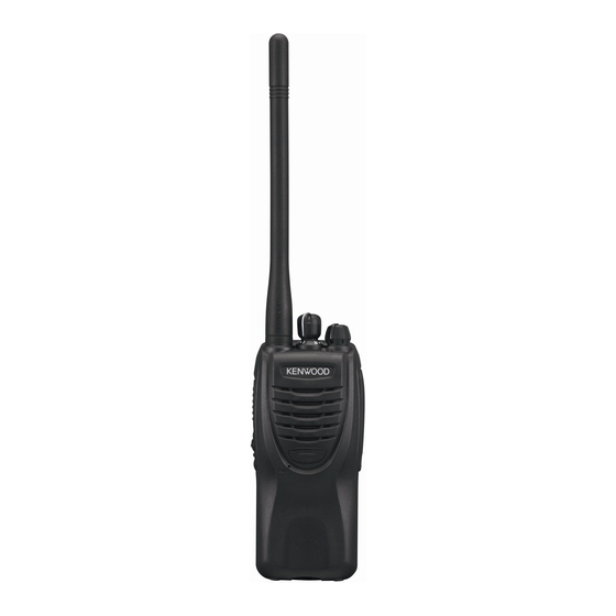
Helical antenna
(T90-1036-15)
Badge (Front)
(B43-1622-04)
Button knob (PTT)
(K29-9425-03)
Button knob
(Side1/Side2)
(K29-9426-03)
Plastic cabinet assy
(A02-4040-03)
RoHS
This product complies with the
Knob (Selector)
(K29-9427-03)
Knob (Volume)
(K29-9309-13)
directive for the European market.
V
(
)
© 2008-9 PRINTED IN JA PAN
B51-8838-00 ( N ) 672
CONTENTS
GENERAL .....................................................2
SYSTEM SET-UP .........................................3
REALIGNMENT ...........................................3
DISASSEMBLY FOR REPAIR ......................6
CIRCUIT DESCRIPTION ..............................9
SEMICONDUCTOR DATA .........................13
TERMINAL FUNCTION .............................13
COMPONENTS DESCRIPTION .................14
PARTS LIST ...............................................15
EXPLODED VIEW ......................................22
PACKING ....................................................23
ADJUSTMENT ..........................................25
TX-RX UNIT (X57-7570-20) ...................30
SCHEMATIC DIAGRAM ............................34
BLOCK DIAGRAM .....................................38
LEVEL DIAGRAM ......................................40
SPECIFICATIONS ......................................41
.
This product uses Lead Free solder.
Advertisement
Table of Contents

Related Manuals for Kenwood TK-2302


Summary of Contents for Kenwood TK-2302
-
Page 1: Table Of Contents
VHF FM TRANSCEIVER TK-2302/2302 TK-2306 SERVICE MANUAL © 2008-9 PRINTED IN JA PAN B51-8838-00 ( N ) 672 CONTENTS GENERAL .............2 SYSTEM SET-UP .........3 Helical antenna Knob (Selector) REALIGNMENT ...........3 (T90-1036-15) (K29-9427-03) DISASSEMBLY FOR REPAIR ......6 Knob (Volume) (K29-9309-13) CIRCUIT DESCRIPTION ......9 SEMICONDUCTOR DATA ......13... -
Page 2: General
Kenwood reserves the right to make changes to any wise, for any purpose without the prior written permission products herein at any time for improvement purposes. -
Page 3: System Set-Up
TK-2302/2302 /2306 SYSTEM SET-UP Frequency range (MHz) RF power Type Merchandise received TK-2302: K,P,M TX/RX 136~174 5.0W TK-2302(V): K Choose the type of transceiver TK-2306: M A personal computer, programming interface (KPG-22/22A), Transceiver programming and FPU (programming software) are required for programming. - Page 4 TK-2302/2302 /2306 REALIGNMENT KPG-22 or KPG-22A or Notes: KPG-22A+KCT-53U • You must install the KCT-53U driver in the computer to Illustration is KPG-22 use the USB adapter (KCT-53U). • When using the USB adapter (KCT-53U) for the fi rst time, plug the KCT-53U into a USB port on the computer with the computer power ON.
- Page 5 TK-2302/2302 /2306 REALIGNMENT 4-3. Operation • Clone frequency table 1. To switch the clone target/s to wireless clone mode, Operating frequency press and hold the [PTT] and [side2] keys while turning 136~174MHz the transceiver power ON. 136.150 2. Wait for 2 seconds. The LED will light orange and the 138.150...
-
Page 6: Disassembly For Repair
TK-2302/2302 /2306 DISASSEMBLY FOR REPAIR 1. Removing the Case Assembly from the Chassis 3. Removing the Battery Release Lever 1. Remove the volume knob q and channel knob w. from the Case Assembly 2. Remove the two screws e. 1. Press the upper part of the lever toward the inside of the 3. - Page 7 TK-2302/2302 /2306 DISASSEMBLY FOR REPAIR 5. Assembling the Battery Release Lever 7. Mounting the Chassis to the Case Assembly 1. Place the lever w onto the stopper q. 1. Confirm that the waterproof packing attached to the 2. Place the thick spring e onto the lever.
- Page 8 TK-2302/2302 /2306 DISASSEMBLY FOR REPAIR 8. Attaching the Antenna Receptacle to the Chassis 10. Screw sequence for mounting the TX- Screw the antenna receptacle to the chassis in the order RX unit to the chassis shown in the drawing so that the antenna receptacle Attach the TX-RX unit to the chassis using the screws in comes to the center of the case hole.
-
Page 9: Circuit Description
TK-2302/2302 /2306 CIRCUIT DESCRIPTION ■ First Mixer 1. Frequency Confi guration The signal from the front end is mixed with the fi rst local The receiver utilizes double conversion. The first IF is oscillator signal generated in the PLL circuit by Q203 to pro- 38.85MHz and the second IF is 450kHz. - Page 10 TK-2302/2302 /2306 CIRCUIT DESCRIPTION ■ Squelch 3. PLL Frequency Synthesizer Part of the AF signal from the IC enters the FM IC (IC201) The PLL circuit generates the fi rst local oscillator signal again, and the noise component is amplifi ed and rectifi ed by for reception and the RF signal for transmission.
-
Page 11: Power Supply
TK-2302/2302 /2306 CIRCUIT DESCRIPTION IC101 (2/2) compares the output voltage of IC101 (1/2) 4. Transmitter System with the reference voltage from IC306. The output of IC101 ■ Microphone Amplifi er (2/2) controls the VG of the RF power amplifier and drive The signal from the microphone passes through the amplifi... - Page 12 TK-2302/2302 /2306 CIRCUIT DESCRIPTION ■ Frequency Shift Circuit R301 IC306 The MCU (IC306) operates at a clock of 14.746 MHz. This oscillator has a circuit that shifts the frequency by BEAT SHIFT SW (Q305, Q306). A beat sound may be able to be evaded from generation if “Beat Shift”...
-
Page 13: Semiconductor Data
TK-2302/2302 /2306 SEMICONDUCTOR DATA MCU: R5F212CCKCMB (TX-RX unit IC306) Pin No. Signal Name Function Pin No. Signal Name Function 5T_C 5T control Serial data input PLL_STB PLL strobe Baseband IC data output 5C_C 5C control DI/O I/O Baseband IC data input / output... -
Page 14: Components Description
TK-2302/2302 /2306 COMPONENTS DESCRIPTION TX-RX unit (X57-7570-20) Ref. No. Part Name Description Ref. No. Part Name Description PLL system IC Q301 Transistor DC switch/ Red color LED Prescaler Q302 Transistor DC switch/ Green color LED IC101 Q303 Transistor DC switch/ 5R... -
Page 15: Parts List
TK-2302/2302 /2306 PARTS LIST CAPACITORS 2 2 0 • Capacitor value CC45 Color* 010 = 1pF 0 = 22pF 1 = Type ... ceramic, electrolytic, etc. 4 = Voltage rating 100 = 10pF 2 = Shape ... round, square, etc. - Page 16 CK73HB1C682K CHIP C 6800PF ✽ K29-9427-03 KNOB (SELECTOR) CC73HCH1H060B CHIP C 6.0PF CC73HCH1H040B CHIP C 4.0PF ✽ N14-0848-05 CIRCULAR NUT (SELECTOR) CC73HCH1H060B CHIP C 6.0PF AK: TK-2302 K AP: TK-2302 P VK: TK-2302(V) K AM: TK-2302 M BM: TK-2306 M...
- Page 17 TK-2302/2302 /2306 PARTS LIST TX-RX UNIT (X57-7570-20) Desti- Desti- Ref. No. Ad dress Parts No. Description Ref. No. Ad dress Parts No. Description parts nation parts nation C44,45 CK73GB1A105K CHIP C 1.0UF C146 CC73GCH1H070B CHIP C 7.0PF CC73HCH1H150J CHIP C...
- Page 18 TK-2302/2302 /2306 PARTS LIST TX-RX UNIT (X57-7570-20) Desti- Desti- Ref. No. Ad dress Parts No. Description Ref. No. Ad dress Parts No. Description parts nation parts nation C264 CC73HCH1H050B CHIP C 5.0PF C400 CK73FB0J106K CHIP C 10UF C265 CC73HCH1H300J CHIP C...
- Page 19 TK-2302/2302 /2306 PARTS LIST TX-RX UNIT (X57-7570-20) Desti- Desti- Ref. No. Ad dress Parts No. Description Ref. No. Ad dress Parts No. Description parts nation parts nation L213 L41-5678-14 SMALL FIXED INDUCTOR (56NH) R104 RK73HB1J220J CHIP R 1/16W L214 L41-2778-14...
- Page 20 TK-2302/2302 /2306 PARTS LIST TX-RX UNIT (X57-7570-20) Desti- Desti- Ref. No. Ad dress Parts No. Description Ref. No. Ad dress Parts No. Description parts nation parts nation R309,310 RK73GB2A000J CHIP R 1/10W S1-3 S70-0414-05 TACT SWITCH R313 RK73HB1J102J CHIP R 1.0K...
- Page 21 TK-2302/2302 /2306 PARTS LIST TX-RX UNIT (X57-7570-20) Desti- Desti- Ref. No. Ad dress Parts No. Description Ref. No. Ad dress Parts No. Description parts nation parts nation TH101 B57331V2104J THERMISTOR TH201 B57331V2104J THERMISTOR...
-
Page 22: Exploded View
TK-2302/2302 /2306 EXPLODED VIEW Ex10 MIC301 TX-RX unit CF201 : N14-0848-05 : N14-0849-05 C M2.6 x 4 : N30-2604-48 D M2.6 x 6 : N30-2606-48 E M2 x 5 : N83-2005-48 Model name plate Parts with the exploded numbers larger than 700 are not supplied. -
Page 23: Packing
42 Item carton case (H52-2300-13) 48 Holder (SP/MIC) (J29-5521-03) 705 Battery assy (Ni-Cd): BM AK: TK-2302 K VK: TK-2302(V) K AM: TK-2302 M 706 Battery assy (Li-ion): AK,VK,AM BM: TK-2306 M Parts with the exploded numbers larger than 700 are not supplied. - Page 24 TK-2302/2302 /2306 PACKING (P TYPE) 7 Instruction manual 70 AC adapter (B62-2139-00) (W08-0970-35) 40 Carton board (H13-2109-03) 704 Protection bag 50 Belt hook (J29-0734-05) 48 Holder (SP/MIC) (J29-5521-03) 68 Helical antenna (T90-1036-15) 4 Cap (B09-0725-03) 707 Battery assy (Ni-MH) 74 Charger (KSC-31)
-
Page 25: Adjustment
TK-2302/2302 /2306 ADJUSTMENT Test Equipment Required for Alignment Test Equipment Major Specifi cations Frequency Range 136 to 174MHz Standard Signal Generator (SSG) Modulation Frequency modulation and external modulation Output –127dBm/0.1µV to greater than –47dBm/1mV Input Impedance 50Ω RF Power Meter... - Page 26 TK-2302/2302 /2306 ADJUSTMENT Frequency and Signaling The transceiver has been adjusted for the frequencies shown in the following table. When required, re-adjust them following the adjustment procedure to obtain the frequen- cies you want in actual operation. ■ Frequency (MHz) Channel No.
- Page 27 TK-2302/2302 /2306 ADJUSTMENT Common Section Measurement Adjustment Item Condition Specifi cations / Remarks Test- Unit Terminal Unit Parts Method equipment 1. Setting 1) BATT terminal votage: 7.5V 2) SSG standard modulation [Wide] MOD: 1kHz, DEV: 3kHz [Narrow] MOD: 1kHz, DEV: 1.5kHz 2.
- Page 28 TK-2302/2302 /2306 ADJUSTMENT Measurement Adjustment Item Condition Specifi cations / Remarks Test- Unit Terminal Unit Parts Method equipment 6. QT Fine 1) TEST CH: Center, Low, High Power 0.75kHz ±40Hz Deviation (3 points) meter [Wide] Deviation meter fi lter Deviation...
- Page 29 TK-2302/2302 /2306 ADJUSTMENT Measurement Adjustment Item Condition Specifi cations / Remarks Test- Unit Terminal Unit Parts Method equipment 2. Sensitivity 1) TEST CH: Low, Center, High Check 12dB SINAD or more [Wide] (3 points) SSG otuput SP/MIC : –117dBm (0.3µV)
-
Page 30: Pc Board
TK-2302/2302 /2306 PC BOARD TX-RX UNIT (X57-7570-20) Component side view (J79-0186-09) F301 C303 BATT+ MIC301 AFMUTE CP301 – C321 R201 C213 AFCONT THDET R309 IC303 MDSW R310 Q304 C331 C318 CN302 C310 RESET CN303 R317 MODE R316 R319 C339 C337... - Page 31 TK-2302/2302 /2306 PC BOARD TX-RX UNIT (X57-7570-20) Component side view (J79-0186-09) J79-0186-09 Q107 L302 R132 C140 C325 Q106 R302 C315 Q108 R303 C313 C304 C311 C307 C305 C130 PCTV R116 R117 IC301 CN301 R120 – R123 Q301 C395 Q302 C396...
- Page 32 TK-2302/2302 /2306 PC BOARD TX-RX UNIT (X57-7570-20) Foil side view (J79-0186-09) J79-0186-09 SIDE1 L116 C158 CP202 R226 L113 C254 C150 C250 L112 R229 C257 R225 C249 C247 L216 C260 R230 C154 C151 C243 C255 C245 R104 C146 C148 C106 C101...
- Page 33 TK-2302/2302 /2306 PC BOARD TX-RX UNIT (X57-7570-20) Foil side view (J79-0186-09) SIDE2 R215 L204 C231 XF201 CD201 R217 R218 Q203 D301 R231 L206 C225 C221 C217 R214 C238 C236 C226 R219 L207 C223 R211 C229 C408 L201 C212 R394 C215...
-
Page 34: Schematic Diagram
TK-2302/2302 /2306 SCHEMATIC DIAGRAM TX-RX UNIT (X57-7570-20) PLL_CLK PLL_DAT 4p(B) 2.86V RK75HA1J101J PLL_STB 470p PLL SYSTEM IC 2SC5636 MB15A02PFV2E1 RF AMP RECTIFICATION KTC4075E(Y,GR) 5.0V 4.92V 0.01u 4.92V TXCO 4.48V F301 L77-3042-05 F53-0324-05 2.5A L301 BATT VCoNT 0.66V BATT oUTPUT 2ND_LO 4.7u... - Page 35 TK-2302/2302 /2306 SCHEMATIC DIAGRAM TX-RX UNIT (X57-7570-20) 4.88V PRESCALER R:3.42V D3,6 UPB1509GV FREQUENCY 270n CONTROL RF AMP VCO (RX) /RX VCO VCC1 VCC2 0.75V 2SC5636 5p(B) 1000p 180n 120p 1SV325F 0.5p VCO/RX 2SK1875-F(V) 3.82V DC SW/ RX VCO RT1P430U R:0.58V T:5.1V...
- Page 36 TK-2302/2302 /2306 SCHEMATIC DIAGRAM TX-RX UNIT (X57-7570-20) R:7.6V R102 T:0.55V TX/RX T:1.21V T:6.95V T:2.71V RF SW R:0V C108 C120 L105 R106 C110 L102 R114 T:1.76V 4.85V MC2858 RF AMP C102 1000p 1000p Q105 Q102 RD07MVS1BT122 2SC5636 Q101 RQA0004PXDQS 100p 2SC4926YD TX FINAL AMP R:1.8V...
- Page 37 TK-2302/2302 /2306 SCHEMATIC DIAGRAM TX-RX UNIT (X57-7570-20) L113 L114 L116 ANT SW C145 C150 CN13 L108 L109 L110 D103 C153 C155 C158 HSC277 1000p 7p(B) L115 L112 ANT SW ANT SW L210 Q204 R:4.82V LOW NOISE AMP L206 R:2.41V Q203 R:4.7V...
-
Page 38: Block Diagram
TK-2302/2302 /2306 BLOCK DIAGRAM Q7:RT1P430U X57-7570-20 (TX-RX UNIT) RX_SW Switch Fuse 2.5A Oscillator: 349.700~ 425.700MHz F301: 5C_C F53-0324-05 Rx VCO Battery Protector Q4:2SK1875-F(V) Voltage D3,D6:1SV325F Regulator 5T_C D301:GN1G Q8:RT1P430U IC303: XC6209B502PR Loop PLL_UL Rectifier TX_SW Switch Switch Filter Q1:KTC4075E(Y,GR) Q304:DTB723YE... - Page 39 TK-2302/2302 /2306 BLOCK DIAGRAM IC101: PCTV BA2904FVM Switch Q103:RT1N441U APC_SW Q107:2SK1824-A Tempera- Switch DC_SW Lipple TH_DET ture Filter Detector Tx/Rx: APC_SW Switch Switch 136.000~ Q6,Q10: TH101 174.000MHz KTC4075E(Y,GR) Protector D101:UDZW5.1(B) Q106:RT1N441U Q108:RT1P441U 5T 5R T1P430U Tx:136.000~ 174.000MHz Frequen- Pre-drive Final...
-
Page 40: Level Diagram
TK-2302/2302 /2306 LEVEL DIAGRAM... -
Page 41: Specifications
TK-2302/2302 /2306 SPECIFICATIONS General Frequency Range ...........136~174MHz Number of channels ..........Max. 16 Channel Spacing ............25kHz, 30kHz (Wide) / 12.5kHz, 15kHz (Narrow) PLL Channel Stepping ...........2.5kHz, 5kHz, 6.25kHz, 7.5kHz Operating Voltage ..........7.5 V DC±20% Battery Life ............More than 18 hours at 5 watts (5-5-90 duty cycle with KNB-45L battery) Operating Temperature range .......–30°C to +60°C (–22°F to +140°F) - Page 42 Unit 3712-3724, Level 37, Tower one Metroplaza, 223 Hing Fong Road, Bp 58416 Villepinte, 95944 Roissy Ch De Gaulle Cedex Kwai Fong, N.T., Hong Kong KENWOOD House, Dwight Road, Watford, Herts., 1 Ang Mo Kio Street 63, Singapore 569110 WD18 9EB United Kingdom...
- Page 43 TK-2302/2302 /2306 TK-2302/2302 /2306 PC BOARD PC BOARD TX-RX UNIT (X57-7570-20) Component side view (J79-0186-09) TX-RX UNIT (X57-7570-20) Component side view (J79-0186-09) J79-0186-09 Q107 L302 R132 C140 C325 Q106 R302 C315 F301 Q108 R303 C313 C304 C311 C303 C307 C305...
- Page 44 TK-2302/2302 /2306 TK-2302/2302 /2306 PC BOARD PC BOARD TX-RX UNIT (X57-7570-20) Foil side view (J79-0186-09) TX-RX UNIT (X57-7570-20) Foil side view (J79-0186-09) J79-0186-09 SIDE1 SIDE2 R215 L204 C231 L116 XF201 CD201 R217 R218 Q203 D301 C158 R231 CP202 L206 C221...
- Page 45 TX-RX UNIT (X57-7570-20) 4.88V L113 L114 L116 R:7.6V TX/RX T:0.55V R102 PLL_CLK T:2.71V T:1.21V T:6.95V ANT SW RF SW R:0V R:3.42V PRESCALER C108 C110 L102 R114 C120 L105 L108 L109 L110 C145 D103 C150 C153 C155 C158 CN13 PLL_DAT T:1.76V R106 D3,6 4.85V...
- Page 46 Q7:RT1P430U IC101: X57-7570-20 (TX-RX UNIT) PCTV BA2904FVM RX_SW Switch Switch Q103:RT1N441U APC_SW Fuse Q107:2SK1824-A 2.5A Tempera- Switch DC_SW Oscillator: Lipple 349.700~ TH_DET ture Filter Detector 425.700MHz F301: 5C_C Tx/Rx: F53-0324-05 Rx VCO APC_SW Switch Switch 136.000~ Q6,Q10: TH101 Battery 174.000MHz KTC4075E(Y,GR) Protector D101:UDZW5.1(B) Protector...