Honda Outboard Motor BF15A Owner's Manual
Honda power equipment outboard motor owner's manual
Hide thumbs
Also See for Outboard Motor BF15A:
- Owner's manual (94 pages) ,
- Owner's manual (112 pages) ,
- Owner's manual (85 pages)
Table of Contents
Advertisement
Advertisement
Table of Contents

Related Manuals for Honda Outboard Motor BF15A


Summary of Contents for Honda Outboard Motor BF15A
- Page 1 Includes Remote Control Supplement...
- Page 3 Thank you for purchasing This manual covers operation and, maintenance Outboard Motor. All information product information available at the time of approval for printing. Honda Motor Co., Ltd. reserves the right to make changes at any time without notice and without No part of this publication This manual should be considered a permanent part of the Outboard Motor and should remain with it if it is resold.
-
Page 4: Table Of Contents
CONTENTS 1 . SAFETY ... 2. COMPONENT IDENTIFICATION 3. INSTALLATION 4. PRE-OPERATION CHECK ... 5. STARTING THE ENGINE ... 6. OPERATION High altitude operation 7. STOPPING THE ENGINE ... 8. MAINTENANCE 9. TRANSPORTING/STORAGE 10. TROUBLESHOOTING 11. SPECIFICATIONS 12. WIRING DIAGRAM 13. -
Page 5: Safety
HONOA before using the Outboard Motor. FLAMMABLE DO NOT USE FUEL/OIL 2.9 IMP.GALLONS BELOW BOTTOM OF NECK. OR FATAL IF SWALLOWED. DO NOT INDUCE VOMITING. CALL PHYSICIAN FROM BOAT MOTOR CO.. LTD. 1. SAFETY STRTINO. OPERATE WITH ENC-~- A CAU’. - Page 6 MANUAL power is properly mounted. to operate the outboard if anyone falls overboard. while the boat is near anyone poisonous carbon monoxide Never run the outboard area. flammable and is explosive area with or sparks where the engine and securely.
-
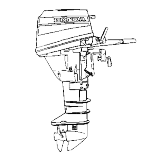
Page 7: Component Identification
2. COMPONENT IDENTIFICATION ENGINE COV;\ ,STARTER GRIP LECTRIC STARTER (Electric starter model only) SHIFT LEVER NGINE STOP BUTTON WATER CHECK HOLE AMP SCREW ENGINE OIL DRAIN SCRE TILT LEVER ANTI-CAVITATION PLATE ENGINE SERIAL NUMBER * Always list the serial number when ordering parts. - Page 8 THROTTLE GRIP THROTTLE FRICTION KNOB HANDLE STERN BRACKET. ADJUSTING GEAR OIL LEVEL BOL WATER INTAKE GEAR OIL DRAIN BOLT’ OIL PRESSURE INDICATOR CHOKE KNOB OIL FILLER CAP OIL LEVEL DIPSTICK LOCK LEVER ANODE METAL EXHAUSTAND DRAINING PORT FUEL LINE CONNECTOR (MALE)
-
Page 9: Installation
The short shaft motor requires som height of about 15 in. The long shaft motor requires about 20 in. Once the boat is in the water loaded, motor depth by looking cavitation plate: with running,... - Page 10 CAUTION: While operating the tightness of the clamp screws occasionally. Tie a rope through stern bracket and secure the other end of the rope to the boat. will prevent accidental motor. NOTE: To prevent the outboard tor from falling accidentally,...
- Page 11 There are five adjusting 1. Push in (A) the adjusting upwards remove. 2. Inserting hole, twist it down CAUTION: prevent the motor or boat, make sure the ad- justing rod is locked. with water CORRECT GIVES MAXIMUM PERFORMANCE by chang- stages.
- Page 12 Do not place the fuel tank near the battery. (for electric starter) Place the battery in a corrosion-resistant box securely to the hull. Install the battery level while the boat is cruising cord with the red terminal the black terminal (+I TERMINAL the (+) side battery cable first.
- Page 13 1. Engine Oil Level CAUTION: Engine oil is a major factor affecting Nondetergent and low quality have inadequate lubricating Running engine damage. Honda 4-stroke equivalent high detergent, quality motor oil certified exceed U.S. automobile turer’s requirements Classification Motor sified SF will show this designation on the container.
- Page 14 2. Fuel Level Check the fuel gauge and refill the tank if.the NOTE: Open the vent knob b’efore removing vent knob is firmly clbsed, Your engine is designed tane number lR + M, of 86 or higher, of 91 or higher.* Gasoline pump octane number.
- Page 15 Gasoline is extremely conditions. Refuel in a well-ventilated or allow flames or sparks where gasoline is stored. Do not overfill the tank (there should refueling, make sure the tank cap is closed Be careful not to spill fuel when ignite. If any fuel is spilled, engine.
- Page 16 3. Other Checks Check the following items. @ The propeller and cotter @The fuel hose for kinking, @The steering handle @The stern bracket @The tool kit for missing @The anode metal for damage, CAUTION: The anode mdtal must remain exposed condition.
-
Page 17: Starting The Engine
1. Preparation Before CAUTION: To prevent run the engine with the propeller 1. Connect the fuel line to the.tank the connectors are securely Be careful vapor may ignite. If any fuel is spilled, starting the engine. NOTE: Position the fuel tank so the tank fuel line connector meter (3.3 ft) below Do not place the fuel tank more than 2 meters motor. - Page 18 2. Starting Exhaust contains BMlm can cause loss of consciousness engine in an enclosed CAUTION: Damage system may occur if the motor is operated water. 1. Put the shift lever in NEUTRAL. 2. Align the throttle handle. poisonous carbon and may lead to death. area.
- Page 19 3. If the engine is “cold”, push it in gradually 4. Pull the starter rope slowly CAUTION: Do not allow the starter gently to prevent damage Do not pull the starter damage the starter. pull out the choke as the engine warm CHOKE KNOB until a resistance...
- Page 20 5. Electric starter (Electric Put the outboard motor in NEUTRAL, start the engine. CAUTION: Do not use the starter to start, release the key, and wait at least 10 seconds the starter motor again; 0 Do not press the electric damage the starting 6.
- Page 21 7. After starting, be sure water CAUTION: If water does not flow engine. Check to see if the screen in the cooling Do not operate the engine is flowing out of the water out, or if steam water until the problem has been corrected.
- Page 22 3. ,Emergency Starting If the recoil starter is not working the, spare starter rope in the tool kit. 1. Remove the engine 2. Remove recoil moving the three 6 mm bolts. 3. Disconnect the neutral ble. 4. Wind spare around pulley engine.
-
Page 23: Operation
For the first 10 hours of operation, and avoid abrupt operation 1. Gear Shifting The gearshift lever has 3 positions: An indicator at the base of the gear shift lever aligns with on the engine case to show Turn the throttle grip to SHIFT to decrease gear shift lever. - Page 24 2. Steering To turn to the right, swing the steering swing the handle to the right. ing wheel are controlled For smooth steering, felt when turning. STEERING FRICTION BOLT- handle to the left. To turn to the left, Boats equipped in the same way as a car.
- Page 25 “RUN” position (page 24). NOTE: For best performance, sengers equipment distributed to balance the boat evenly from side to side and parallel water from front to back. in the forward throttle grip speed. throttle at a ‘steady...
- Page 26 4. Tilting the Motor Tilt the motor to prevent when the boat is beached 1. Stop the engine and put the shift lever into NEUTRAL. 2. Pull the tilt lever toward the engine to either the 30”, CAUTION: Do not use the throttle 70”...
- Page 27 When the outboard Never operate in reverse board motor will rise and may To avoid damaging CAUTION: ing the boat, especially strike a pier or other boats. to the normal RUN position, it stops, tilt the engine out from the cooling...
- Page 28 5. High altitude operation At high altitude, the standard rich. performance will decrease, High altitude performance main fuel jet in the carburetor operate the outboard level, have your authorized carburetor modifications. Even with suitable carburetor proximately 3.5% for each 1,000 altitude on horsepower tion is made.
-
Page 29: Stopping The Engine
7. STOPPING THE ENGINE grip to “SLOW” position and move the shift lever to 1. Turn the throttle NEUTRAL. NEUTRAL 2. Push and hold the stop button depressed until the engine stops running. CAUTION: In the event that the engine does not stop when you hold the stop button,... -
Page 30: Maintenance
8. MAINTENANCE Periodic maintenance the best operating condition. Shut off the engine engine must be run, make sure the area is well ventilated. engine in an enclosed or confined monoxide gas; exposure death. CAUTION: If the engine must above the cavitation sufficient cooling water,... - Page 31 Tool kit and spare parts The following tools and spare parts are supplied for maintenance, adjustment, The tool kit and oil bottle 9 x 12 mm WRENCH 10 x 12 mm WRENCH 8 mm WRENCH FLAT SCREWDRIVER PHILIPS SCREWDRIVER OIL CHECK SCREWDRIVER SPARE FUSE (ELECTRIC STARTER MODEL ONLY) and emergency...
- Page 32 Engine Oil Change Drain the oil while the engine draining. 1 i Remove the engine drain the oil. Reinstall OIL FILLER CAP 2. Refill to the upper mended oil (see p. 11). OIL CAPACITY: 1.1 P (I .2 US qt) OIL LEVEL DIPSTICK 3.
- Page 33 Gear Oil Check/Change Oil Level Check Check the oil level when the engine is in the vertical level screw and see if oil flows scerw hole until the oil starts there is water in the oil, the water will flow out first when the drain screw is removed, or the oil will be a milky color.
- Page 34 Spark Plug Service Recommended spark plug: To ensure proper engine ped and free of deposits. 1. Remove the engine 2. Remove the spark plug caps. 3. Use the wrench supplied SPARK PLUG WkENCH 4. Visually inspect the spark plugs. parent wear, or if the insulators plugs with...
- Page 35 6. Thread the plugs in by hand to prevent 7. After the spark plugs are seated, compress the washers. NOTE: If installing new spark plugs, tighten seat to compress the washers. l/8- turn after the spark plugs seat to compress CAUTION: The spark plugs must be securely can become...
- Page 36 Replacing fuse (electric model) If the fuse blows, running will not charge battery. replacing the fuse, check the current ratings of the connecting ensure that there are no abnormal- ities. <How to replace the fuse> 1. Stop the engine. 2. Remove the engine 3.
- Page 37 Cleaning and Flushing After each use in salt water water, thoroughly clean and flush the outboard motor. (With Water Hose Joint-Optional Part) 1. Wash the outside of the outboard motor with clean, fresh water. 2. Remove the flush bolt. 3. Flush cooling the water hose joint (optional).
- Page 38 (Without Water Hose Joint) Wash the outside of the outboard motor with clean, fresh water. Remove the propeller. Stand the motor in a suitable tainer Of water. The water must be at least 4 inches the anti-cavitation Start the engine and run slowly at least 5 minutes.
- Page 39 Lubrication Wipe the outside of the engine ticorrosion grease to the following SHIFT SHAFT AND PIVOT ;;tO$TLE CA:,. ADJUSTING NOTE: Apply anti-corrosion penetrate. with a cloth dipped parts: GEAR SHIFT ARM oil to pivot surfaces in oil. Apply marine an- :OVER LOCK LEVER rlLT LINKAGE PROPELLER SHAFT...
- Page 40 Propeller Change If the propeller is damaged by striking a rock, or other obstacle, replace the propeller as follows. 1. Remove the cotter pin, then remove the 14 mm castle nut, plain washer, and the propeller. ‘i 2. Install the new ,propeller in the reverse sequence to removal.
- Page 41 Fuel filter replacement The fuel filter is located sediment accumulated starting. To prevent engine ((SERVICE PERIOD)) Every 200 operating Gasoline is flammable smoke or allow flames fuel. Always work in a well-ventilated Be sure that any fuel drained container. Be careful not to spill fuel when vapor may ignite.
- Page 42 4. Remove the clamps used to close the fuel tubes. Connect the fuel tank line to the motor. Turn the fuel tank vent knob to the ON position, pump the primer bulb, and check for leaks. If loss of power or hard starting is found to be caused by excessive NOTE:...
- Page 43 Servicing a Submerged A submerged motor must from the water in order to minimize If there is a Honda outboard mediately to the dealer. If you are far from a dealership, 1. Remove the engine remove salt water, 2. Loosen the carburetor buretor into a suitable 3.
-
Page 44: Transporting/Storage
9. TRANSPORTING/STORAGE 1. Disconnect the fuel line and install the cap on the engine fuel inlet. Firm- ly close the fuel cap vent knob. 2. Loosen the carburetor container. After draining, Be careful not to spill fuel. Spilled fuel is spilled, make sure the area is dry before storing motor. - Page 45 CAUTION: To avoid damaging ing or moving the boat. handle, or hold by the carrying here. Do not carry by the the motor, never use it as a handle for lift- INCORRECT...
- Page 46 4. Transport and store the motor either vertically here, with the steering Vertical transport or storage: Attach stern stand. Horizontal transport .Rest the motor on the case protec- (steering handle motor). CAUTION: Ariy other transport oil leakage. handle raised. bracket or storage: side of th...
- Page 47 5. Tilt up the outboard several times, and completely CAUTION: If the outboard draining off the cooling enter the engine from the exhaust cooling water before putting When pulling the starting 6. Pull the starting grip until closes, preventing dust from entering 7.
- Page 48 IO. TROUBLESHOOTPNG Engine’ Will Not Start: 1. Is the shift lever in neutral? 2. Is there fuel in the fuel tank? 3. Is the fuel cap knob turned 4. Is the fuel system primed 5. Is fuel reaching the carburetor? Loosen the carburetor float...
-
Page 49: Specifications
MODEL Description Code output Recommended full throttle range Engine type Displacement Valve tappet clearance Spark plug gap Starter system x height Overall length Standard Propeller (No. of 11. SPECIFICATIONS BF9.9A S Model BABS 9.9 hosepower (Maximum) 4,500-5,500 4 stroke OHC in-line twin 280 cc (17.1 cu in) - Page 50 MODEL Description Code output Recommended full throttle range Enaine tvoe Displacement Valve tappet clearance Spark plug gap Starter system Ignition system Lubrication system Specified Oil capacity D.C. output Cooling system Exhaust system Spark pluas Fuel pump Fuel Tank caoacitv Steerina eauipment Tilt angle Anole...
- Page 51 &REMOTE CONTROL H. 1 --!j @jCAM PULLY 8, ... y ... “EUOy/ PULSER COIL & ... BL”E G ... GREEN R ... RED w ... W",TE ~,,,,,,,,,//,N/////////////////////// LAMP CONSENT 8, ... BROWN 0 ... ORANGE Lb ... UGHT BLUE Lg ... UGHT GREEN p ...
- Page 52 ~~,,~,,,,,,,,,,~,~,,,,~~ /REMOTE CONTROL ~NN///N///N///////,,,,,,,,,,,,,,,,,,,,,,,,,,,,,,,,,,,,,,,,,,, 9 L- IZOW 5 ~,,,,,,,,,,,,,,,,,,,,,,,,,,,,,,,,,,,,,,,,,,,,,,,,,,,,,,,,,,,,,,,,,,,~ ENGINE CIRCULATION PRESSURE k;DJ$ATOR SWITCH CDI UNIT -FLY WHEEL PULLY ml-J yug)w B’JJE &r&g R ... RED w ... w’.“x ENGINE STOP SWITCH W(JWN ORANGE Lb ... UGHT BLUE U ... LIGHT GREEN p ...
-
Page 53: Optional Parts
13. OPTIONAL PARTS Lamp consent kit for engine without electric starter Charging coil kit for engine with electric starter Water hose joint mouth seat Water mouth nut Safety switch kit... - Page 54 14. WARRANTY Owner Satisfaction Your satisfaction and goodwill Honda warranty details are explained Normally, any problems dealer’s service department. been handled to your action: Discuss your problem complaints can be quickly already been reviewed the dealership or the General If your problem still has not been resolved Power Equipment...
- Page 55 Current customer service contact information: Your owner's manual was written to cover most of the questions you might ask about your Honda. Any questions not answered in the owner's manual can be answered by your Honda dealer. If your dealer doesn't have an immediate answer, they should be able to get it for you.
- Page 57 Owner's Manual Outboard Motor BFg.yA/15A I I I I I I I I I I I I I I I I I I I I I <SUPPLEMENT> @ 1993 American Honda Motor Co., Inc. - All Rights Reserved I I I I I I I I I...
- Page 59 Thank you for purchasing This owners manual supplement remote control equipped BF9.9A/15A owner’s manual for all other information. The owner’s manual and this supplement contain information on how to operate your new outboard motor safely. Please read them carefully. Keep the owners manual and this supplement handy, so you can refer to them at any time, and be sure they accompany the outboard motor if you sell it.
-
Page 60: Wiring Diagram
CONTENTS 2. COMPONENT IDENTIFICATION 3. INSTALLATION (see remote control installation 4. PRE-OPERATION 5. STARTING THE ENGINE 6. OPERATION 7. STOPPING THE ENGINE 12. WIRING DIAGRAM 13. OPTIONAL PARTS The- owners manual. These sections are not covered in this supplement. The NON-HIGHLIGHTED mote Control Equipped BF9.9A/15A. - Page 61 SPARE STOP S EMERGENCY SWITCH LANYARD REMOTE C HARNESS 2. COMPONENT NEUTRAL RELEASE LEVER OIL PRESSURE INDICATOR EMERGENCY SWITCH CLIP EMERGENCY ENGINE STOP SWITCH 2 IDENTIFICATION LIGHT CHOKE/FAST EMERGENCY ENGINE STOP STOP...
-
Page 62: Pre-Operation Check
3. PRE-OPERATION Steering friction bolt Operate the steering wheel right and left and check for the amount of drag felt. Adjust the steering friction bolt so that a slight amount of drag is felt. The steering should move smoothly and freely. STEERING FRICTION BOLT Remote control friction adjustment... - Page 63 F (forward): Moving the lever to the F position will engage the forward gear. Moving the lever farther from the F position will increase the throttle opening and the boat forward speed. N (neutral): The engine idles and the transmission...
- Page 64 5. STARTING THE ENGINE Neutral release lever The neutral release lever is on the re- mote control lever to prevent an acci- dental gear engagement. The remote control lever will not engage forward or reverse gear unless the neu- tral release lever is pulled up. Ignition switch The remote control box is equipped with a key type ignition switch.
- Page 65 Emergency stop switch lanyard The emergency stop switch lanyard is provided to stop the engine immediately in the event the operator should fall overboard or away from the controls. The emergency stop switch clip must be engaged with the emergency engine stop switch or the engine will not start.
- Page 66 5. STARTING THE ENGINE Choke/Fast idle lever The choke/fast idle lever provides two functions: 1. Electric choke solenoid activation for easy engine start up. 2. Engine fast idle. The choke/fast idle lever will not move unless the remote control lever is in the N (neutral) position.
- Page 67 Oil pressure indicator light The green oil pressure turns OFF when the oil level is low and/or the engine lubrication faulty. 5. STARTING THE ENGINE indicator light system is...
- Page 68 If the operator does not attach the emergency is thrown from his seat or out of the boat, the out-of-control seriously injure the operator, erly attach the lanyard before starting the motor. A spare emergency...
- Page 69 2. Move the control lever to the N (neutral) position. The engine will not start unless the control lever is in the N (neutral) position. 3. When the engine is cold and/or the ambient temperature hold the choke/fast fully. This will provide mixture and the correct fast idle.
- Page 70 5. STARTING THE ENGINE 5. After starting the engine, return the lever slowly to the position the engine does not stall. Hold the lever in position. The control lever will not move un- less the choke/fast turned to the lowest position. 6.
- Page 71 7. With the engine running, check to see if the green engine oil pressure indicator light turns ON. Stop the engine if the oil pressure indicator light does not turn ON. Check the engine oil level. If the oil level is normal and the oil pressure indicator light does not turn ON, contact your closest authorized Outboard Motor dealer.
- Page 72 5. STARTING THE ENGINE Recoil starting If the electric starting system will not start the engine. The engine can be started using the recoil starter. 1. Move the control (neutral) position. 2.Turn the ignition key to the ON position. Engage the emergency stop switch clip, located at one end of the...
- Page 73 4. If the engine is cold and/or ambient temperature and hold the manual out. The choke knob is located on the front of the outboard If the fuel system is working erly, it should only be necessary pull the recoil starter with the choke knob out.
- Page 74 5. STARTING THE ENGINE Electric starting (starter button) If the choke solenoid kit is not installed or not working, the engine can be started using the starter button on the side of the engine. 1. Perform steps 1 - 5 in this supplement 2.
- Page 75 30” toward F (forward) or 30” toward R (reverse) to engage the desired gear. Moving the control lever farther from 30” will increase throttle opening and boat speed. (neutral) The control lever will not move unless the neutral release lever is pulled up and the choke/fast idle lever is in the lowest position.
- Page 76 1. Move the control lever to the N (neutral) position. 2.Turn the ignition key to the OFF position. When the boat is not in use, remove and store the ignition stop switch EMERGENCY engine stop STOP SWITCH 1 EMERGENCY CONTRO LEVER key.
- Page 78 13. OPTIONAL PARTS Steering lube Seal (Anodized Aluminum or Stainless Steel) There are additional optional parts available. See your authorized Honda Marine or Honda Outboard Motor dealer for a complete list.
- Page 80 2509307 31 ZV46QA PRINTED IN U.S.A. 00X31-ZV4-6OOA...