Table of Contents
Advertisement
Quick Links
MITSUBISHI ELECTRIC
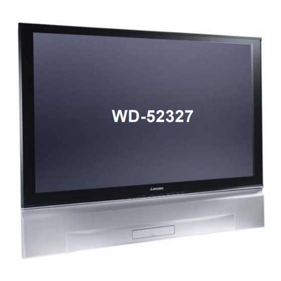
WD-52327
CAUTION:
Before servicing this chassis, it is important that the service person read the "SAFETY PRECAUTIONS" and
"PRODUCT SAFETY NOTICE" contained in this manual.
• Power Input
• Power Usage
• Light Engine
• Light Source
• Frequency Range
• Antenna Input
• Cabinet Dimensions
• Weight
• Speakers (8 Ohms 10W)
: 2-5 inch Coaxial
• Design specifications are subject to change without notice.
MITSUBISHI DIGITAL ELECTRONICS AMERICA, INC.
SPECIFICATIONS
: AC 120V, 60Hz
: 200W
: DLP (1280 x 720p pixels)
: 120W VIP
: VHF 54 ~ 470MHz
UHF 470 ~ 806MHz
: VHF/UHF 75Ω unbalanced
2 - NTSC
WD-52327
: 37.2"(H) x 49.6"(w) x 17.4"(D)
WD-62327
: 43.7"(H) x 58.3"(W) x 19.9"(D)
[WD-52327] 110 lbs
[WD-62327] 139 lbs
9351 Jeronimo Road, Irvine, CA 92618-1904
Copyright © 2004 Mitsubishi Digital Electronics America, Inc.
All Rights Reserved
Ser
Ser
vice
vice
Ser vice
vice
Ser
Ser
vice
Manual
Manual
Manual
Manual
Manual
DIGITAL LIGHT PROCESSING™ PROJECTION TV
VK26 CHASSIS
MODELS
WD-52327
WD-62327
• Input Level
: VIDEO IN JACK (RCA Type)
1.0Vp-p 75Ω unbalanced
: AUDIO IN JACK (RCA Type)
-4.7dBm 43kΩ unbalanced
: S-VIDEO IN JACK
(Y/C separate type)
Y:1.0 Vp-p C:0.286Vp-p(BURST)
75Ω unbalanced
: COMP / Y, Cr, Cb (RCA Type)
Y: 1.0 Vp-p Cr, Cb: 700mVp-p
: DTV / Y(G), Pr(R), Pb(B), H, V
Y: 1.0Vp-p with sync 75Ω (BNC)
Pr, Pb: 700mV 75Ω
H, V: 3.0Vp-p 75Ω
• Output Level
: VIDEO OUT JACK (RCA Type)
1.0Vp-p 75Ω unbalanced
: AUDIO OUT JACK (RCA Type)
-4.7dBm 4.7kΩ unbalanced
• Digital
: MonitorLink
.
2004
2004
2004
2004
2004
TM
/DVI
Advertisement
Table of Contents

Related Manuals for Mitsubishi Electric WD-52327


Summary of Contents for Mitsubishi Electric WD-52327
- Page 1 : AUDIO OUT JACK (RCA Type) -4.7dBm 4.7kΩ unbalanced • Digital : MonitorLink /DVI • Design specifications are subject to change without notice. MITSUBISHI DIGITAL ELECTRONICS AMERICA, INC. 9351 Jeronimo Road, Irvine, CA 92618-1904 Copyright © 2004 Mitsubishi Digital Electronics America, Inc. All Rights Reserved...
-
Page 3: Table Of Contents
MODEL: WD-52327 / WD-62327 CONTENTS INTRODUCTION ..........................5 PRODUCT SAFETY NOTICE ......................5 SAFETY PRECAUTIONS ......................... 6 DISASSEMBLY WD-52327 & WD-62327 Front Cabinet Components ....................7 Rear Cabinet Components ..................... 8 CHASSIS REMOVAL Chassis removal procedure ....................9 Shield Removal ........................10 Chassis PWB locations ....................... - Page 4 MODEL: WD-52327 / WD-62327 Switched DC to DC Supplies ....................43 Video/Color Signal Path ....................... 44 Sound Signal Path ....................... 45 Sync Signal Path ......................... 46 Control Circuit (Commands, Serial Data & Reset) ..............47 Control Circuit (Status Inputs, OSD Insert & CCD Insert) ............48 PWB-FORMAT Block Diagram ....................
-
Page 5: Model: Wd-52327 / Wd
MODEL: WD-52327 / WD-62327 INTRODUCTION This service manual provides service instructions for PTV models WD-52327 and WD-62327, using the VK26 chassis. This service manual includes: 1. Assembly and disassembly instructions for the front and rear cabinet components. 2. Servicing of the Lenticular Screen and Fresnel Lens. -
Page 6: Safety Precautions
MODEL: WD-52327 / WD-62327 SAFETY PRECAUTIONS NOTICE: Observe all cautions and safety related notes located inside the receiver cabinet and on the receiver chassis. WARNING: Operation of this receiver outside the cabinet or with the cover removed presents a shock hazard from the receiver's power supplies. -
Page 7: Disassembly Wd-52327 & Wd-62327 Front Cabinet Components
MODEL: WD-52327 / WD-62327 CABINET DISASSEMBLY (FRONT VIEW) WD-52327 / WD-62327 *Refer to the Parts List for Part Numbers Front Cabinet Disassembly 1. Remove the SPEAKER-GRILLE by pulling forward. 2. Remove screws (a) to remove the COVER-FRONT. 3. Remove screws (b) on the rear of the upper back cover (4 across the top and 3 on each side). -
Page 8: Rear Cabinet Components
MODEL: WD-52327 / WD-62327 REAR DISASSEMBLY FILTER-COVER Removal Remove 2 screws (d) to remove the Filter Cover. COVER-BACK Removal 1) Remove 9 screws (a) NOTE: To operate the TV with the COVER-BACK removed, 2) Remove 6 screws (b) the FILTER-COVER must be reinstalled. -
Page 9: Chassis Removal
MODEL: WD-52327 / WD-62327 CHASSIS REMOVAL Chassis Removal Procedure 1) Disconnect all relay connectors shown below (JE, CC, JJ, PP, LL & EE) 2) Disconnect the J9 and DVI connectors at the Optical Engine. 2) Remove three screws (a) securing the chassis. -
Page 10: Shield Removal
MODEL: WD-52327 / WD-62327 Shield Removal 1) To remove SHIELD-COVER, remove 11 screws (a). 2) To remove PWB-TERMINAL COVER, remove 9 screws (b). Page 10... -
Page 11: Chassis Pwb Locations
MODEL: WD-52327 / WD-62327 VK26 Chassis PWB Locations (Shield-Cover removed) Page 11... -
Page 12: Accessing The Lamp Ballast
MODEL: WD-52327 / WD-62327 Accessing The Lamp Ballast Removing the Right Support (Rear View) 1) Remove the Air Filter. 2) Remove the 3 screws (a). 3) Lift the upper cabinet slightly to remove the support bracket. Lift upper cabinet slightly to remove support. -
Page 13: Optical Engine Replacement
MODEL: WD-52327 / WD-62327 OPTICAL ENGINE REPLACEMENT Optical Engine is mounted on the Adjuster assembly as shown below. 1) The Optical Engine is secured to the bottom plate with 4 screws (b). 2) The Black Bracket is secured to the bottom plate and the Lamp Cartridge Housing with 4 screws (c). -
Page 14: Removing The Optical Engine
MODEL: WD-52327 / WD-62327 Removing the Optical Engine 1) Remove the Cabinet BACK-BOARD and REAR-PLATE (refer to disassembly instructions). 2) Disconnect all connectors connected to the Engine and the PWB-FORMAT. 3) From the rear of the TV, remove the 4 screws (c), to remove the COVER-DUCT and DMD Fan cover. -
Page 15: Removing Dmd Heat Sensor
MODEL: WD-52327 / WD-62327 Remove the follolwing parts from the Optical Engine • DMD Thermal Sensor • The Optical Engine bottom plate and black bracket DMD Termal Sensor Removal (Figure 1) 1) Remove screw (a) on the top of the DMD Fan. -
Page 16: Installing The Optical Engine
MODEL: WD-52327 / WD-62327 Black Bracket Front View Figure 3: Black Support Bracket Installing the Optical Engine 1) Install the Bottom Plate, Black Support Bracket and the Thermal Sensor from the original Optical Engine, on the replacement Engine 2) Reverse the removal procedure to install the replacement Optical Engine in the cabinet. -
Page 17: Servicing The Lenticular Screen And Fresnel Lens
MODEL: WD-52327 / WD-62327 SERVICING THE LENTICULAR SCREEN AND FRESNEL LENS CAUTION: Wear gloves when handling the Lenticular Screen and Fresnel Lens. This prevents cuts and finger prints. Do not place Fresnel Lens in the sun. This may cause fire and heat related injuries. - Page 18 MODEL: WD-52327 / WD-62327 Figure 2: BEZEL Removal (Front View) Figure 3: Lenticular Screen & Fresnel Lens Removal (Rear View) Page 18...
-
Page 19: Installation Of The Lenticular Screen And Fresnel Lens
MODEL: WD-52327 / WD-62327 SERVICING THE LENTICULAR SCREEN AND FRESNEL LENS Lenticular Screen and Fresnel Lens Installation Note: Store the Lenticular Screen and Fresnel Lens in a cool dry place. High humidity may deform the Lenticular Screen and Fresnel Lens. -
Page 20: Electrical Adjustments
MODEL: WD-52327 / WD-62327 ELECTRICAL ADJUSTMENTS Note: Perform only the adjustments required. Do not attempt an alignment if proper equipment is not available. Test Equipment • Oscilloscope (Unless otherwise specified, use 10:1 probes) • Signal Generator (NTSC Color Bar) Test Signals A. -
Page 21: Initial Setup (Option Menu)
MODEL: WD-52327 / WD-62327 Initial Setup A. Option Menu Setup Follow the steps below for the initial set-up: 1. Select the "MENU" display by pressing the "MENU" button once. 2. Press the number buttons "5", "7", "7", "0" in sequence to select the "OPTION MENU" display. -
Page 22: A/V Memory Defaults
MODEL: WD-52327 / WD-62327 A/V Memory Defaults Function Ant -A/B Comp-1/2 Input 1/2/3 MonoLink Contrast Maximum Maximum Maximum Maximum Maximum Brightness Center Center Center Center Center Sharpness Center Center Center Center Center Color Center Center Center Center Center Tint Center... -
Page 23: Led Dignostic Check
MODEL: WD-52327 / WD-62327 LED Diagnostic Check 1. Initial Control Circuitry Check Immediately after the TV is connected to an AC power source: 2. Error Code Operational Check Pressing the front panel “INPUT” and “MENU” buttons at the same time, and holding for 5 seconds, activates the Error Code Mode. - Page 24 MODEL: WD-52327 / WD-62327 B. Selection of adjustment Functions and Adjustment Items To select an adjustment item in the circuit adjustment mode, first select the adjustment function that includes the specific item to be adjusted. Then select that adjustment item.
-
Page 25: Adjustment Items List
MODEL: WD-52327 / WD-62327 List of Service Adjustment Items MAIN MATRIX (Main Decoder) Stored in IC2K02 on PWB-TERMINAL Item No. Abbrev, Description Data Range Initial Data SCNT Main Y-Gain 0~31 SCLR Main CB/CR Gain 0~31 SUB MATRIX (Sub Decoder) Stored in IC2K02 on PWB-TERMINAL Item No. -
Page 26: Activating Internal Test Patterns
MODEL: WD-52327 / WD-62327 Activating & Selecting an Internal Test Signal CAUTION 1. Select an External Input with no signal. DO NOT press “MENU” (or HOME) without 2. Press the buttons “MENU”-“5”-“7”-“5”-“7” in pressing “9” first. (The Video Mute function will sequence. -
Page 27: Adjustment Procedures
MODEL: WD-52327 / WD-62327 [Video Circuit] Purpose: To set picture luminance 1. Main/Sub Y Level Symptom: Excess or insufficient brightness. Measuring Oscilloscope 1. Supply a color bar signal to a Video Input (not an RF input). Instrument 2. Select the color bar signal for both the main and sub pictures. -
Page 28: White Balance Adjustments
MODEL: WD-52327 / WD-62327 Purpose: [Video Circuit] To set high, mid and low temperature white levels. Symptom: 3. White Balance White areas have a color tint. Measuring Instrument 1. Supply a 100% white raster to an External Video Input. 3. Activate the Service Mode. (MENU-5-7-5-7) Test Point 4. -
Page 29: Mechanical Adjustments
MODEL: WD-52327 / WD-62327 Mechanical Adjustments • To perform the mechanical adjustments, the TV must be on a flat level surface and a certain amount of disassembly is required. • Use internal Test Pattern B for all mechanical adjustments. Front Disassembly Refer to the diagram below for the Front Panel removal procedures. -
Page 30: Picture Rotation Adjustment
MODEL: WD-52327 / WD-62327 Picture Rotation Adjustment NOTE: The TV must be on a flat level surface. 1. From the front of the TV, lift the foam to access and loosen slightly, the brass Rotation Locking Screws on the Adjuster Assembly, Figure 4A. -
Page 31: Horizontal & Vertical Keystone Distortion Adjustments
MODEL: WD-52327 / WD-62327 Keystone Adjustment Horizontal Keystone Distortion Vertical Keystone Distortion NOTE: The TV must be on a flat level surface 1. From the front of the TV, loosen the two Keystone Locking Screws in the small mirror assembly. (10mm wrench) 2. -
Page 32: Quick Reference Part List
MODEL: WD-52327 / WD-62327 QUICK REFERENCE FOR COMMON REPLACEMENT PARTS • Critical Electrical Components are indicated by Bold Type in the Parts List Customer Replaceable Parts P a rt Na m e De scription W D-52327 W D-62327 La m p Ca rtridge... -
Page 33: Service Parts List
MODEL: WD-52327 / WD-62327 Model Legend: [a] WD-52327, [b] WD-623275 Ref # Part # Part Name & Description Ref # Part # Part Name & Description INTEGRATED CIRCUITS IC9C01 270P928010 IC - BA17809FP IC9C11 270P928010 IC - BA17809FP IC2D00 270P974010... - Page 34 MODEL: WD-52327 / WD-62327 [#] Model Legend: [a] WD-52327, [b] WD-62327 Ref # Part # Part Name & Description Ref # Part # Part Name & Description D9A33 264P458050 DIODE - RD3.9EB1 L2P32 325C461050 COIL-PEAKING - 15MH-K D9A34 262P090010 DIODE - M1FP3...
- Page 35 MODEL: WD-52327 / WD-62327 Model Legend: [a] WD-52327, [b] WD-623275 Ref # Part # Part Name & Description Ref # Part # Part Name & Description L7K01 409P777080 EMI-F-CHIP - BLM21P221S LC1A13 409P876020 EMI-F-CHIP - CNF20C470S/CKD510JB1H470S L7M90 409P777080 EMI-F-CHIP - BLM21P221S...
- Page 36 MODEL: WD-52327 / WD-62327 [#] Model Legend: [a] WD-52327, [b] WD-62327 Ref # Part # Part Name & Description Ref # Part # Part Name & Description LC8E07 409P876020 EMI-F-CHIP - CNF20C470S/CKD510JB1H470S 103P491000 1/16W 240-F 103P503070 1/16W 10K-J 103P501080 1/16W 270-J...
- Page 37 MODEL: WD-52327 / WD-62327 Model Legend: [a] WD-52327, [b] WD-623275 Ref # Part # Part Name & Description Ref # Part # Part Name & Description R9A89 103P141090 R-CARBON 1/2W 330-J C2AJB 142P024060 C-CER - BF50V 0.1M-Z R9A90 103C394020 R-METAL-P - 3W 27K...
- Page 38 MODEL: WD-52327 / WD-62327 [#] Model Legend: [a] WD-52327, [b] WD-62327 Ref # Part # Part Name & Description Ref # Part # Part Name & Description C2P26 181P350060 C-ELEC - 3V 1000M-M C9A08 189P185090 C-CER - AC250V E2200P-M C2P32...
- Page 39 MODEL: WD-52327 / WD-62327 Model Legend: [a] WD-52327, [b] WD-623275 Ref # Part # Part Name & Description Ref # Part # Part Name & Description C9C34 181P354060 C-ELEC - 35V 100M-M 635B114020 MIRROR - BRACKET - TOP C9C35 181P355050...
- Page 40 MODEL: WD-52327 / WD-62327 [#] Model Legend: [a] WD-52327, [b] WD-62327 Ref # Part # Part Name & Description Ref # Part # Part Name & Description PRINTED CIRCUIT BOARDS COSMETIC PARTS 930B929001 ASSY-PWB-POWER 760A016010 INLAY TERMINAL 930B930001 ASSY-PWB-SIGNAL 761A233010...
-
Page 41: Screen Parts List
MODEL: WD-52327 / WD-62327 Model Legend: [a] WD-52327, [b] WD-623275 Ref # Part # Part Name & Description Ref # Part # Part Name & Description SCREEN ASSEMBLY PARTS WD-52327 WD-62327 491P175010 LENS-FRESNEL 491P175020 LENS-FRESNEL 491P176030 SCREEN-LENTICULAR 491P176040 SCREEN-LENTICULAR 623D174010... -
Page 42: Standby Power Supplies
MODEL: WD-52327 / WD-62327 Page 42... - Page 43 MODEL: WD-52327 / WD-62327 Page 43...
- Page 44 MODEL: WD-52327 / WD-62327 Page 44...
- Page 45 MODEL: WD-52327 / WD-62327 Page 45...
- Page 46 MODEL: WD-52327 / WD-62327 Page 46...
- Page 47 MODEL: WD-52327 / WD-62327 Page 47...
- Page 48 MODEL: WD-52327 / WD-62327 Page 48...
- Page 49 MODEL: WD-52327 / WD-62327 Page 49...
- Page 50 MODEL: WD-52327 / WD-62327 Page 50...