Epson TM-U220 Series Service Manual
Tm-u220 series
Hide thumbs
Also See for TM-U220 Series:
- User manual (197 pages) ,
- Reference manual (152 pages) ,
- Service manual (90 pages)

Related Manuals for Epson TM-U220 Series


Summary of Contents for Epson TM-U220 Series
-
Page 1: Service Manual
Confidential Service manual TM-U220 Series (Type A) Issued date Issued by English 404619501 Rev. B EPSON... - Page 2 On the earlier of (a) termination of your relationship with Seiko Epson, or (b) Seiko Epson’s request, you must stop using the confidential information. You must then return or destroy the information, as directed by Seiko Epson.
-
Page 3: Table Of Contents
Differences between the TM-U300, TM-U200, and TM-U220 ........1-8... - Page 4 Confidential TM-U220 Type A Service Manual DIsassembly Procedures ............4-7 Disassembling the Carriage Unit .
-
Page 5: Revision Table
Confidential Revision Table Revision Pages Description Rev. A All pages Newly authorized. Rev. B Part names added. Control panel (LEDs and buttons) added. Inserting roll paper added. Installing and replacing the ribbon cassette added. 4-3, 4-4 Illustration was changed. 4-5, 4-16, 4-17 An explanation of the roll paper cover assembly was added. -
Page 6: For Safe Repair And Maintenance Work
Confidential TM-U220 Type A Service Manual For Safe Repair and Maintenance Work Key to Symbols The symbols in this manual are identified by their level of importance, as defined below. Read the following carefully before handling the product. WARNING: You must follow warnings carefully to avoid serious bodily injury. -
Page 7: Safety Precautions On Maintenance/Repair/Inspection
Confidential Safety Precautions on Maintenance/Repair/Inspection WARNING: Be sure to use the EPSON-supplied fuse on the circuit board. Use of another fuse may result in fire. Remove the power cord and all other cables from this product before disassembly or reassembly to prevent electrical shock. -
Page 8: About This Manual
Confidential TM-U220 Type A Service Manual About this Manual Aim of the Manual This manual was created to provide the information on printer maintenance and repair required by technicians who handle this work. Manual Content The manual is made up of the following sections Provides an overview of the product. -
Page 9: Chapter 1 Product Overview
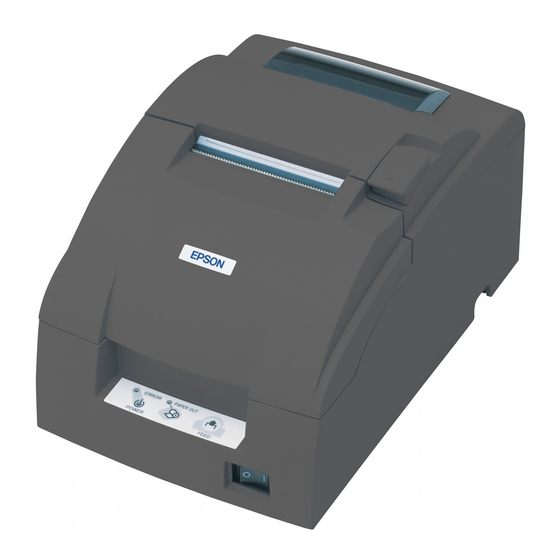
Chapter 1 Product Overview The TM-U220 is a serial impact dot-matrix printer for POS systems that can print on roll paper of various widths. This manual describes the TM-U220 Type A, which has a take-up shaft for journal paper. The following model types are available for the TM-U220. -
Page 10: Configurations
Confidential Configurations This TM-U220 is configured by combining features from the list below. Table 1-1 Configurations Features Selection Description UB-S01 (RS-232) UB-P02II (IEEE 1284 (bidirectional parallel)) Interface types Use an EPSON-approved interface board EPSON UB universal interface board options Be sure to change the paper guide spacer if paper of a different width is used. -
Page 11: Control Panel (Leds And Button)
Confidential TM-U220 Type A Service Manual Control Panel (LEDs and Button) LEDs POWER On when power is on. ERROR On when printer is offline. Off when printer is online. Flashes during an error. PAPER OUT On when paper is out or nearly out. Flashes during self-test... -
Page 12: Inserting Roll Paper
Confidential Inserting Roll Paper CAUTION: Be sure to use only roll paper that meets the specifications. Be sure not to touch the manual cutter. Otherwise, you may cut your fingers. 1. Using scissors, cut the leading edge of the roll paper. 2. - Page 13 Confidential TM-U220 Type A Service Manual 4. Insert the roll paper. Note: Note the direction that the paper comes off the roll, as shown above. When using two-ply paper, be sure that the top and bottom sheets are aligned at the paper exit. Do not allow paper to be loaded as shown below.
- Page 14 Confidential 7. Close the unit, as shown below. 8. Insert the end of the bottom layer of paper (journal paper) into the paper take-up flange, as shown below. Take-up flange 9. Insert the paper take-up flange into the printer. Be sure that the paper is aligned with the flange, as shown.
-
Page 15: Installing Or Replacing The Ribbon Cassette
CAUTION: EPSON recommends the use of only genuine EPSON ribbon cassettes. Ribbon cassettes not manufactured by EPSON may cause damage to your printer that is not covered by EPSON’s warranties. To install the ribbon cassette for the first time or to replace a used ribbon, follow the steps below. -
Page 16: Differences Between The Tm-U300, Tm-U200, And Tm-U220
Confidential Differences between the TM-U300, TM-U200, and TM-U220 Specification TM-U300 (Type A, B, C, D) TM-U200 (Type A, B, D) TM-U220 (Type A, B, D) Print speed 3.5 lines/second (at 40 columns, 16 cpi) 3.5 lines/second (at 40 columns, 16 cpi) 4.7 lines/second (at 40 columns, 16 cpi) -
Page 17: Chapter 2 Repair Guide
Confidential TM-U220 Type A Service Manual Chapter 2 Repair Guide This chapter gives instructions to complete repair of the product. Follow the process in this section for repair. Repair Process Outline of Repair Check each item before and after repair, as shown in the following flowchart. This chapter explains the operations to confirm a “normal state”... -
Page 18: Self-Test
Confidential Printer Status Checks Operation Normal printer operation When a problem occurs POWER LED does not light. (See page 3-3.) Power LED light comes on. ERROR LED light. (See page 3-3.) Power on. Mechanical initializing operation occurs. ERROR LED flashes. (See page 3-4.) ERROR LED light is off. - Page 19 Confidential TM-U220 Type A Service Manual Printer Status Print Normal printout result Explanation Version information Main program version Boot program version Interface classification Interface information Receive buffer capacity *1) Busy release conditions for receive buffer full *2) Busy condition *3)
- Page 20 Confidential Roll Pattern Normal print result Explanation Black (6 lines) Red (6 lines) Red (6 lines) Paper feeds 2 lines. Paper is fed to a position where the user can see the ending message at left 2-4 Repair Guide Rev. B...
-
Page 21: Service Utility
4. Test the communication. 1. Model selection: Select the TM-U220 (Type A model printer). 2. Communication condition selection: Select the I/F used with the printer. You can confirm the communication conditions set for the printer by running the self-test. Refer to the self-test section for details. - Page 22 Confidential Real-time status: Lets you confirm sensor operations, such as cover open/close, in real time. Printer status: Lets you read and set the printer values collectively. Also, you can save the settings to a file, read the set values in the file, and the display the default state. Refer to the chapter on adjustment settings.
- Page 23 Communication function: You can confirm that communication with the printer is enabled/disabled. Setting function: Reads and prints on the status sheet the status settings for EPSON NV memory, memory switches, communication conditions, and customized value. Receipt print function: Prints patterns to confirm print operations and print quality.
- Page 24 Confidential 1. Indicate the sensor to test. 2. Follow the message to operate the printer. 3. Click If you want to skip the test. When the sensor detects the printer operation correctly, OK is displayed. When the sensor is not installed (depending on the printer model), you can skip with the Skip button.
- Page 25 Confidential TM-U220 Type A Service Manual Output result When the printer operates normally, the following sheet is printed. Refer to the chapters on “Troubleshooting” and “Adjustment and Setting” when print results differ. Receipt Print Normal print result Explanation Prints execution date.
-
Page 26: Status Print
Status Print Normal print result Explanation Prints execution date. Prints execution time. Prints “EPSON.” Prints “TM-U220.” Prints product serial number. *1) Prints setting status of memory switches. *2) Prints setting status of customize value. *3) Performs partial cut. *4) Note: *1) When the serial number is not registered on the product itself, “NG”... - Page 27 Displays size of extended ROM. (Differs depending on specifications.) Prints defined bit image data in NV memory. *1) Prints defined data in NV user memory. *2) Prints information on EPSON NV memory. It is changeable with the printer status. *3) Manufacturer name Model name Product serial no.
- Page 28 Normal print result Explanation Prints execution date. Prints execution time. Prints “EPSON.” Prints “TM-U220.” Prints the serial number for the product. Prints the execution status of all function test. Prints test results of sensor operation. *1) Note: *1) When an operation such as cover open sensor check is skipped using the button on the screen, the report shows a problem for that item.
-
Page 29: Chapter 3 Troubleshooting
Confidential TM-U220 Type A Service Manual Chapter 3 Troubleshooting Preparations for Troubleshooting Before troubleshooting, check and, if necessary, correct the following points. Paper is jammed inside the printer CAUTION: Be sure not to touch the manual cutter. Otherwise, you may cut your fingers. -
Page 30: Before Servicing
Confidential 3. Return the cutter blade to the normal position by rotating the autocutter knob in the direction of the arrow. When the blade is returned to the normal position, the lever moves to the center of the hole in the autocutter frame. Hole Lever Autocutter unit... -
Page 31: Symptoms And Solutions
Confidential TM-U220 Type A Service Manual Symptoms and Solutions Symptoms when Power is On POWER LED does not light Table 3-1 POWER LED not Lit Probable part/probable cause Checkpoints Action to correct the problem Check the connections. Make sure the Plug in the connector. -
Page 32: Error Led Flashes
Confidential ERROR LED flashes Table 3-3 ERROR LED Flashes Probable part/probable cause Checkpoints Action to correct the problem Home position detection error Check for jammed paper Remove any jammed paper. around the carriage. Make sure Completed if operation is normal. there is no paper jam. -
Page 33: Troubleshooting
Confidential TM-U220 Type A Service Manual Table 3-3 ERROR LED Flashes Probable part/probable cause Checkpoints Action to correct the problem CPU execution error Check the connection of the I/F circuit board unit (122). Make Connect the I/F circuit board unit sure the connector is plugged (122). - Page 34 Confidential PAPER OUT LED lights Table 3-4 PAPER OUT LED is Lit Probable part/probable cause Checkpoints Action to correct the problem Check the roll paper. Make sure it is Replace the roll paper. Completed if Roll paper loaded correctly. Make sure enough the PAPER OUT LED turns off.
- Page 35 Confidential TM-U220 Type A Service Manual When only the initializing operation is executed Table 3-5 Only the Initializing Operation Occurs Probable part/probable cause Checkpoints Action to correct the problem For the serial I/F, check the reset function setting for pins # 6 and # 25. If the I/F...
- Page 36 Confidential Table 3-6 The Printer Does not Print Probable part/probable cause Checkpoints Action to correct the problem Check the connectors. Make sure they are plugged in securely: Plug in the connectors. Completed if Paper feed motor sub assembly (1046) operation is normal. Connector (CN8) on the main circuit PF (paper feed) lead wire set board unit (201)
- Page 37 Confidential TM-U220 Type A Service Manual Paper is fed, but characters are not printed Table 3-7 Paper is Fed, but Characters do not Print Probable part/probable cause Checkpoints Action to correct the problem Check the ribbon mounting. Make sure Load the ribbon cassette correctly.
- Page 38 Confidential Table 3-8 ERROR during Printing Probable part/probable cause Checkpoints Action to correct the problem Check the parts on the main circuit board unit (201) for Replace the main circuit board unit damage. Make sure the (201). Completed if operation is following parts look normal.
- Page 39 Confidential TM-U220 Type A Service Manual Paper is not cut correctly Table 3-9 Cutter not Working Correctly Probable part/probable cause Checkpoints Action to correct the problem Check the setting of DSW 2-2. Switch DSW 2-2 to ON. Completed if DIP switch setting OFF: Autocutter is disabled.
- Page 40 Confidential Print result is not normal Print is light or irregular Table 3-11 Light or Irregular Print Probable part/probable cause Checkpoints Action to correct the problem Check the ribbon mounting. Make Install the ribbon cassette correctly. sure it is installed correctly. Completed if printing is normal.
- Page 41 Confidential TM-U220 Type A Service Manual Line spacing is irregular Table 3-14 Irregular Line Spacing Probable part/probable cause Checkpoints Action to correct the problem Load roll paper that meets Roll paper is inserted Check the roll paper. Make sure it meets specifications correctly.
-
Page 42: Paper Jam Occurs
Confidential Printed contents are not normal Table 3-16 Abnormal Printing Content Probable part/probable cause Checkpoints Action for the problem Check the version number. (See page 2-1.) Update the firmware. Completed Firmware version Make sure it is the same as the version used if printing is normal. -
Page 43: Symptoms When The All Function Test Is Executed
Confidential TM-U220 Type A Service Manual Table 3-17 Paper Jams Probable part/probable cause Checkpoints Action to correct the problem Clean, so that both paper guide Check operation. Make sure the 2 rollers rollers (1045) rotate correctly. rotate smoothly. Completed if operation is normal. - Page 44 Confidential Communication test fails Table 3-19 Communication Test Failure Probable part/probable cause Checkpoints Action to correct the problem Check the communication settings. Make Set the correct communication sure the settings printed by the self-test are Communication condition settings. Completed if operation is the same as the communication settings normal.
- Page 45 Confidential TM-U220 Type A Service Manual Printed output is not normal Table 3-20 Abnormal Output is Printed Probable part/probable cause Checkpoints Action to correct the problem When a question mark (?) is printed, check communication settings. Make Select DTR/DSR control. Completed...
- Page 46 Confidential Cannot pass one of the tests for a sensor Cannot pass the NE (near-end) sensor test Table 3-22 Test for the NE Sensor Fails Probable part/probable cause Checkpoints Action to correct the problem Check connection. Ensure cable is plugged in. Be sure the NE lead wire set (1096) is connected to the connectors Plug in the connector.
- Page 47 Confidential TM-U220 Type A Service Manual Cannot pass the test for the roil cover Table 3-24 Paper Roll Cover Test Fails Probable part/probable cause Checkpoints Action to correct the problem Check the setting of MSW 8-5. If the setting is OFF, status is not sent from the roll...
-
Page 48: Symptoms For Other Operations
Confidential Symptoms for other operations Parts do not move smoothly Cannot take up the roll paper smoothly Table 3-27 Opening and Closing the Roll Paper Cover Assembly is not Smooth Probable part/probable cause Checkpoints Action to correct the problem Confirm that the paper take-up shaft Confirm that the paper take-up assembly assembly (134) is attached correctly. -
Page 49: Test Points On The Main Circuit Board Unit
Confidential TM-U220 Type A Service Manual Test Points on the Main Circuit Board Unit Table 3-30 Test Points on the Main CIrcuit Board Unit Test Component Correct Power supply Pin name Status connector connector value Semiconductor switch on — —... -
Page 50: Resistance Values Of Printer Mechanism Components
Confidential The locations of the main elements on the main circuit board unit are identified below. Resistance Values of Printer Mechanism Components Part Name Internal Element Function Where to Check Normal Status Carriage motor 4-phase stepping motor Head carriage Remove the cable connector Approx. -
Page 51: Chapter 4 Disassembly And Assembly
The EPSON selection of lubricants prescribed for use with the printer is based on the results of such research. The prescribed EPSON lubricants are available in 40 cc (40 gr) metal cans or plastic containers (the smallest unit of supply). -
Page 52: Notes For Assembly And Disassembly
Confidential Use the grease or oil types indicated below for lubrication. Items Parts code Note 1041442 O-13 Grease 1080605 G-15 1080619 G-36 Use items in the list below when operating the printer. Items Parts code Note AC adapter 2081786 — Ribbon cassettes S0152440000 ERC-38 (B) -
Page 53: Shortest Route For Disassembly Of Major Parts
Confidential TM-U220 Type A Service Manual Shortest Route for Disassembly of Major Parts The diagram below shows the shortest route for disassembly of major parts. Perform disassembly by following this diagram as well as the explanations for the target item. -
Page 54: Disassembling The Tm-U220
Confidential Disassembling the TM-U220 Exploded diagram 1084 1092 1099 1111 1110 1085 1004 1095 4-4 Disassembly and Assembly Rev. B... -
Page 55: Disassembly Procedures
Confidential TM-U220 Type A Service Manual Disassembly Procedures Disassembly steps Part names Disassembly procedures Roll paper cover Open the roll paper cover assembly (119). assembly (119) Push and take out the open lever shaft (1001), and then remove 1 screw (S02). -
Page 56: Disassembling The Mechanism Assembly
Confidential Disassembling the Mechanism Assembly Exploded diagram 1114 1125 1104 1129 1108 1005 1047 1010 1038 1013 1046 515 S11 1018 1009 1093 1110 1106 S05 1119 1105 1006 1050 1011 1112 1049 4-6 Disassembly and Assembly Rev. B... -
Page 57: Disassembly Procedures
Confidential TM-U220 Type A Service Manual DIsassembly Procedures Disassembly Part names Assembly procedures steps Take-up belt (523) Remove the back case (130). Remove the take-up gear shaft (139). After that, remove the paper take-up gear assembly (131). Remove the take-up belt (523). -
Page 58: Disassembling The Carriage Unit
Confidential Disassembling the Carriage Unit Exploded diagram 1022 1089 1025 1081 1029 1086 1011 1128 1026 1097 1030 1128 1027 1034 4-8 Disassembly and Assembly Rev. B... -
Page 59: Disassembly Procedures
Confidential TM-U220 Type A Service Manual DIsassembly Procedures Reassembly Part names Assembly procedures steps Ribbon frame Remove the ribbon frame spring (1022). assembly (519) Remove 1 E-ring 4 (E03), and remove the ribbon frame assembly (519). After this, you can remove the print head unit (503). -
Page 60: Disassembling The Rotation Frame Unit
Confidential Disassembling the Rotation Frame Unit Exploded diagram 1125 1054 1058 1053 1061 1057 1055 1056 4-10 Disassembly and Assembly Rev. B... -
Page 61: Disassembly Procedures
Confidential TM-U220 Type A Service Manual DIsassembly Procedures Reassembly steps Part names Assembly procedures Platen release lever Remove 2 E-rings 3 (E01), and remove the platen release lever (504) (504) and platen shaft (1054). Lubricate the platen shaft (1054) with G-15. -
Page 62: Disassembling The Roll Paper Guide / Roll Paper Holder
Confidential Disassembling the Roll Paper Guide / Roll Paper Holder Exploded diagram 1101 1039 1096 1041 1126 1042 1040 1043 1045 1038 1010 4-12 Disassembly and Assembly Rev. B... -
Page 63: Disassembly Procedures
Confidential TM-U220 Type A Service Manual DIsassembly Procedures Use the steps below for disassembling the roll paper holder. Reassembly steps Part names Assembly procedures Paper end assembly Remove the paper end assembly (514). (514) When replacing the paper end assembly (514), you need to pull out the wire attached on the HP circuit board. -
Page 64: Disassembling The Autocutter Unit / Fixed Blade Holder Assembly
Confidential Disassembling the Autocutter Unit / Fixed Blade Holder Assembly Exploded diagram 1090 1071 1016 1017 1127 1102 1015 1014 4-14 Disassembly and Assembly Rev. B... -
Page 65: Disassembly Procedures
Confidential TM-U220 Type A Service Manual DIsassembly Procedures Use the steps below for disassembling the autocutter unit. Reassembly steps Part names Assembly procedures Cutter cover Remove the cutter cover assembly (115). assembly (115) Lubricate the cutter frame assembly (114) with G-36. -
Page 66: Disassembly And Assembly Reference
Confidential Disassembly and Assembly Reference Removing the Roll Paper Cover Assembly 1. Push the shaft and take it out from the inside of the frame. 2. Remove 1 screw. 3. Release the hooks in 3 positions, as shown. 4. Remove 2 screws. Open lever shaft (1001) Removing and Attaching the Top Case When removing the top case, release both hooks,... - Page 67 Confidential TM-U220 Type A Service Manual Removing and Attaching the Top Case (Continued) Lift the case to remove as shown at right. Removing and Attaching Rotation Spring R When removing the springs, push the springs to the inside to release each hook, as shown.
- Page 68 Confidential Attaching the Paper Hold Spring Place the paper hold spring on the fixed blade holder, as shown. Attaching the Fixed Blade Holder Assembly and Manual Cutter Holder Spring Hole Fixed blade holder assembly Hook Attaching the Cover Open Assembly When attaching the cover open assembly to the frame, be sure that the wires are threaded through the hole.
- Page 69 Confidential TM-U220 Type A Service Manual Leading the Autocutter Unit Wires Guard tube and lead wires Guard tube and lead wires Be sure there is slack in the cable, as shown. Autocutter unit cable This is the point for attaching the top case hook. When attaching the top case, be sure not to catch the autocutter unit cable at this point.
- Page 70 Confidential Attaching Platen Rotation Plate 2 Confirm that the edge of platen rotation Platen rotation plate 2 plate 2 does not touch the edge of platen rotation frame 2. The point not to touch is marked with red in the illustration. Platen rotation frame 2 Attaching the Platen Release Spring When attaching the...
- Page 71 Confidential TM-U220 Type A Service Manual Attaching Platen Assembly 3 (522) 1. Attach platen assembly 3 (522) to the platen frame (1053) with 2 screws (S09) from upper of the platen rotation frame 2 (1125). 2. Attach platen assembly 3 (522) to the platen frame (1053) with 2 screws (S10) from left side of the platen rotation frame 2 (1125).
- Page 72 Confidential Attaching the Take-up Belt Install the back case (130) onto the mechanism assembly. After that, install the take-up belt (523) and paper take-up gear assembly (131) onto the back case. Put the back case sheet over the hole in the back case. Paper take-up gear assembly (1110) Take-up gear shaft (139) Paper take-up gear assembly (131)
- Page 73 Confidential TM-U220 Type A Service Manual Attaching the Carriage Belt Carriage belt Carriage sub assembly Attaching the Head FFC When attaching the FFC to the frame, be sure that the FFC is threaded as shown. Rev. B Disassembly and Assembly 4-23...
- Page 74 Confidential Attaching the Carriage Sub Assembly When assembling the carriage unit, be sure the carriage sub assembly is attached to the carriage guide plate as shown. When removing the adjustment roller shaft holder, rotate it as shown. Carriage guide plate Adjustment roller shaft holder Carriage sub assembly Attaching the HP Board Assembly...
- Page 75 Confidential TM-U220 Type A Service Manual Attaching the Roll Paper Guide Unit Roll paper guide unit Wires Rev. B Disassembly and Assembly 4-25...
- Page 76 Confidential Wiring Placement for Each Cable The illustration below indicates paths for the cable wiring. Cover open assembly wires (515) Paper feed motor sub assembly wires (1046) HP board assembly wires (518) Wires in the NE lead wire set (1096) Wires in the PF lead wire set (1047) 4-26 Disassembly and Assembly...
- Page 77 Confidential TM-U220 Type A Service Manual Attaching Each Cable to the Main Circuit Board CN2: Connecting the cable for the autocutter unit (113) CN4: Connecting the cable for the HP board assembly (518) CN6: Connecting the cable for the NE lead wire set (1096)
-
Page 78: Lubrication Reference
Confidential Lubrication Reference Lubrication Some lubrication points are indicated in the illustrations below. See the first few pages of this chapter for additional information about lubrication, and also see the oil drop icons beside text passages in the disassembly procedure tables for various printer components. 4-28 Disassembly and Assembly Rev. - Page 79 Confidential TM-U220 Type A Service Manual Lubricate the contact points between the carriage shaft and carriage sub assembly (2 points) with O-13. Carriage sub assembly Carriage shaft Lubricate 1 point on the carriage sub assembly with G-36. Lubricate one point on the carriage guide plate with G-36.
- Page 80 Confidential Oil the joint of the paper feed reduction gear 1 (1093) and the NE detector lever (1043). Paper feed reduction Oil (G-36) gear 1 (1093) E-ring 3 (E01) NE detector lever Oil the joint of the paper feed reduction gear 2 and the paper feed reduction shaft 2. Paper feed reduction gear 2 Oil (G-36) E-ring 3 (E01)
-
Page 81: Chapter 5 Adjustment And Setting
Confidential TM-U220 Type A Service Manual Chapter 5 Adjustment and Setting Setting the Installation Position for the Roll Paper Near-End Detector This printer allows you to change the installation position for the roll paper near-end detector using the following steps. -
Page 82: Adjusting The Detection Point For The Roll Paper Near-End Detector
Confidential Adjusting the Detection Point for the Roll Paper Near-End Detector Below are 2 reasons the roll paper NE detector might require an adjustment: To adjust the detection for the diameter of the roll paper core. To adjust the amount of remaining paper before the sensor detects a near end. 1. -
Page 83: Setting The Paper Roll Width
TM-U220 Type A Service Manual Setting the Paper Roll Width The TM-U220 accommodates 76 mm {3"}, 69.5 mm {2.74"}, and 57.5 mm {2.26"} width paper rolls with no adjustments. For the each roll width, use the roll paper spacer included with the printer. -
Page 84: Setting The Autocutter
Confidential Setting the Autocutter The TM-U220 autocutter can be set to either “partial cut“ or “full cut“ using the steps below. Note: Do not change the cutting type from partial cut to full cut after the printer has been used. Otherwise, the printer may not be reliable, because the wear-out level of the cutter blade differs. -
Page 85: Platen Gap Adjustment
TM-U220 Type A Service Manual Platen Gap Adjustment Adjust the platen gap on the reassembled TM-U220 printer unit. Use the following steps to adjust the platen gap for the printer. Adjust the printer’s platen gap when you have performed any one of the following: Disassembly Items Requiring Platen Gap Adjustment of the Printer When you have replaced or removed the platen assembly. -
Page 86: Carriage Belt Tension Adjustment
Confidential Carriage Belt Tension Adjustment 1. Loosen the screw for the belt tension plate assembly. Hook the end of the tension gauge to the hole in the belt tension plate assembly, adjust the tension properly, and tighten with the screw. 2. -
Page 87: Adjust Various Settings
Confidential TM-U220 Type A Service Manual Adjust Various Settings The items below can be adjusted for this printer: DIP switches (communication condition, busy condition, print column, receive buffer capacity, etc.) Memory switches (serial communication conditions, roll paper width, cover open status handling, etc.) - Page 88 Confidential Look at the numbers and letters in the area indicated in the illustration. If the last letters are “US,” use the “US” tables on the next page. If the last letters are “STD,” use the “STD” tables below. Note: The switch functions are shown in the following sections.
- Page 89 Confidential TM-U220 Type A Service Manual US Tables Serial Model (DIP Switch 1) (DIP Switch 2) SW Function SW Function Data receive error Ignored Prints “?” Print column 42/35 40/33 Receive buffer 40 bytes Reserved Fixed to On — capacity...
-
Page 90: Memory Switches
Confidential Memory Switches This printer has memory switches, which are software switches that can be set to On or Off with the memory switch setting utility. Available memory switch settings include MSW 2, MSW 8, the customized value setting, and serial communication condition. Settings are shown in the table below. - Page 91 Confidential TM-U220 Type A Service Manual Note: MSW 8-5: When Off is selected, the status bit for "roll paper end sensor" is transmitted from the printer every time the roll paper cover is opened or closed. When On is selected, the status bit for "roll paper cover open / close"...
-
Page 92: Memory Switch Setup Mode
Confidential Memory Switch Setup Mode The following settings are available in the memory switch setup mode: Basic serial communication conditions (serial interface only) Receive buffer full release condition (MSW 8-7) Roll paper width (customized value) Cover open status (MSW 8-5) Note: All new settings are lost if the power is turned off during the memory switch setup mode. - Page 93 Confidential TM-U220 Type A Service Manual Press the FEED button the number of times required to select the desired “Serial interface settings” transmission conditions. Press FEED button Setting selected 0 ~ 3 times: No change 4 times: 19200 bps 5 times:...
-
Page 94: Chapter 6 Preparation For Shipment
Confidential TM-U220 Type A Service Manual Chapter 6 Preparation for Shipment Follow the instructions below before sending the printer back to the customer. Inspection and Maintenance Perform inspection and maintenance procedures described below properly to allow this unit to operate for the years of trouble-free operation for which it is designed. -
Page 95: Removing Dirt, Paper Chips, And Dust From Inside The Printer
Confidential Removing Dirt, Paper Chips, and Dust from Inside the Printer Wipe off stains with a clean, dry cloth. If the stains do not wipe off, use a neutral detergent. CAUTION: Check the amount of lubrication on each cleaned area and lubricate as needed. See “Lubricants”... -
Page 96: Appendix Parts List
Confidential TM-U220 Type A Service Manual Appendix Parts List Reference Number List Table A-1 Parts List by Reference Number Ref. # Service Manual Name Parts Price List Name Qty. Supplied as a part? Power switch cover Cover,power switch M-T88 shield tube... - Page 97 Confidential Table A-1 Parts List by Reference Number Ref. # Service Manual Name Parts Price List Name Qty. Supplied as a part? Platen rotation plate 2 Plate,platen rotation,2 Cover open lever A Lever ,cover open,A Take-up gear shaft Shaft,take-up gear Operation label D Label,operation,D Rubber foot B...
- Page 98 Confidential TM-U220 Type A Service Manual Table A-1 Parts List by Reference Number Ref. # Service Manual Name Parts Price List Name Qty. Supplied as a part? 1014 Paper hold spring Spring,paper hold 1015 Paper hold roller Roller,paper hold 1016...
- Page 99 Confidential Table A-1 Parts List by Reference Number Ref. # Service Manual Name Parts Price List Name Qty. Supplied as a part? 1056 Platen release spring Spring,platen release 1057 Gear plate D sub assembly Plate,gear,D sub assembly 1058 Paper feed reduction gear 2 Gear,paper feed reduction,2 1059 Paper feed reduction shaft 2...
- Page 100 Confidential TM-U220 Type A Service Manual Table A-1 Parts List by Reference Number Ref. # Service Manual Name Parts Price List Name Qty. Supplied as a part? 1105 Take-up transmission gear Gear,take-up transmission 1106 Middle take-up gear Gear,take-up middle 1107...
- Page 101 Confidential Table A-1 Parts List by Reference Number Ref. # Service Manual Name Parts Price List Name Qty. Supplied as a part? CBS screw, 3X6, F/ZN C.B.S. Screw,3X6,F/ZN CBS- TITE, 3X5, F/ZN C.B.S- TITE,3X5,F/ZN CPSPS screw C.P.S.P.S. Screw CBS-TITE, 3X4, F/ZN C.B.S-TITE,3X4,F/ZN CPS(O) screw C.P.S.(O) Screw...
- Page 102 EPSON Printed in Japan SEIKO EPSON CORPORATION...