
Related Manuals for Sony TRINITRON KV-G14L2J


Summary of Contents for Sony TRINITRON KV-G14L2J
-
Page 1: Service Manual
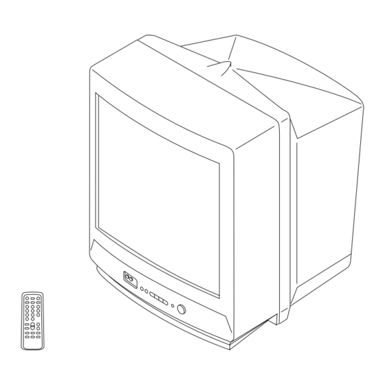
SERVICE MANUAL BG-2S CHASSIS MODEL COMMANDER DEST. CHASSIS NO. MODEL COMMANDER DEST. CHASSIS NO. KV-G14L2J RM-869 ME SCC-U07G-A KV-G21M2J RM-869 ME SCC-U07F-A TRINITRON COLOR TV ®... -
Page 2: Specifications
CARBON PAINTED ON THE CRT, AFTER REMOVING THE PARTS LIST ARE CRITICAL TO SAFE OPERATION. REPLACE ANODE. THESE COMPONENTS WITH SONY PARTS WHOSE PART NUMBERS APPEAR AS SHOWN IN THIS MANUAL OR IN SUPPLEMENTS PUBLISHED BY SONY. – 2 –... -
Page 3: Table Of Contents
KV-G14L2J/G21M2J RM-869 TABLE OF CONTENTS Section Title Page Section Title Page 1. GENERAL 6. DIAGRAMS ..............6-1. Block Diagram ............2. DISASSEMBLY 6-2. Circuit Boards Location ........2-1. Rear Cover Removal ........... 6-3. Schematic Diagrams and Printed Wiring Boards 2-2. -
Page 4: General
SECTION 1 The operating instructions mentioned here are partial abstracts from the Operating Instr uctions Manual. The page numbers of the Operating GENERAL Instruction Manual remain as in this manual. TV/VIDEO – VOLUME + SELECT – PROGR + SELECT – PROGR + ˘... - Page 5 Getting Started Connections Connecting optional equipment You can connect optional audio/video equipment to your TV such as a VCR, multi disc player, camcorder, or video game. … Connecting video equipment using the (video input) jack Front of TV Camcorder … ≥...
- Page 6 Presetting channels Presetting channels automatically Presetting channels manually Disabling program positions Press SELECT on the remote commander or Press SELECT on the remote commander or Press PROGR +/– or number buttons on the the TV until “AUTO PROGRAM” appears on the TV until “MANUAL PROGRAM”...
- Page 7 Operations If no buttons or controls are pressed for more than two hours Watching the TV Turning off the TV Displaying on-screen information after the TV is turned on using the Wake Up Timer, the TV automatically turns into standby mode. If you want to To turn off the TV temporarily continue watching the TV, press any button or control on the Press...
-
Page 8: Adjusting The Picture
Additional Information No picture Adjusting the Troubleshooting Adjusting the picture setting No sound picture Press SELECT until the item you want to adjust appears. SELECT / Press / Check the antenna connection. / Check the VCR connections. Each time you press SELECT, the screen changes as / Check the power cord connection. -
Page 9: Disassembly
SECTION 2 DISASSEMBLY 2-3. SERVICE POSITION 2-1. REAR COVER REMOVAL Four screws (BVTP 4 16) A board 2 Two screws (BVTP 4 16) 2-2. A BOARD REMOVAL Lever Lever A board... -
Page 10: Replacement Of Parts
2-4. REPLACEMENT OF PARTS 2-5. TERMINAL BOARD BRACKET REMOVAL For replacement of the Multi Button and Light Guide, cut the welded portions Terminal board bracket from them, exchange with the new parts, and fix them with screws (+BVTP) respectively. Terminal board bracket 2-4-1. -
Page 11: Picture Tube Removal
2-7. PICTURE TUBE REMOVAL 3 C board 4 Deflection yoke 2 A board 5 Four screws 2 Using a thumb press down, then pull up the rubber cap firmly in the direction indicated (Tapping screws) by the arrow b. 1 Anode cap Anode button 3 When one side of the rubber cap is separated from the anode button, the anode-cap can be removed by turning up the rubber cap and pulling it up in the direction of the... -
Page 12: Set-Up Adjustments
KV-G14L2J/G21M2J RM-869 SECTION 3 SET-UP ADJUSTMENTS The following adjustments should be made when a complete Perform the adjustments in the following order: realignment is required or a new picture tube is installed. 1. Beam Landing These adjustments should be performed with rated power 2. -
Page 13: Convergence
KV-G14L2J/G21M2J RM-869 3-2. CONVERGENCE Operation of V.STAT magnet. If the V.STAT magnet is moved in the direction of the a and Preparation : b arrows, the red, green and blue dots move as shown below. Before starting this adjustment, adjust the focus, horizontal size, and vertical size. -
Page 14: Focus Adjustment
KV-G14L2J/G21M2J RM-869 (2) Dynamic Convergence Adjustment Preparation : Before starting this adjustment, adjust the horizontal static convergence and the vertical static convergence. 1. Slightly loosen the deflection yoke screws. 2. Remove the deflection yoke spacer. 3. Move the deflection yoke as shown in the figure below and optimize the convergence. -
Page 15: G2 (Screen) And White Balance Adjustments
KV-G14L2J/G21M2J RM-869 a. AN ITEM OF ADJUSTMENT 3-4. G2 (SCREEN) AND WHITE BALANCE Item Adjustment Initial DATA Note number Item ADJUSTMENTS WHITE POINT R 1. G2 (SCREEN) ADJUSTMENT (RV701) WHITE POINT G 1) Set the PICTURE and BRIGHTNESS to normal. -
Page 16: Self Diagnosis Function
KV-G14L2J/G21M2J RM-869 SECTION 4 SELF DIAGNOSIS FUNCTION If no acknowledgement is returned from a device which is turned "ON", the device has a problem. In this case, one of the LED's responding to the problem device will flicker a defined number of times. -
Page 17: Circuit Adjustments
KV-G14L2J/G21M2J RM-869 SECTION 5 CIRCUIT ADJUSTMENTS 5-1. ADJUSTMENTS WITH COMMANDER Service adjustments are made with the RM-869 that comes with 1, 4 this unit. Raise/lower the service item number 3, 6 Raise/lower the data [MUTING] Writes Entering service mode Executes the writing... -
Page 18: Adjustment Method
KV-G14L2J/G21M2J RM-869 5-2. ADJUSTMENT METHOD Item Number 08 Use the same method for Items Number 00-40. Use 1 and 4 to This explanation uses V-SHIFT as an example. select the adjustment item, use 3 and 6 to adjust, write with 1. - Page 19 KV-G14L2J/G21M2J RM-869 Adjustment Item Table Item Initial Standard Data Standard Data Note for Different Data Function Device Item Data (KV-G14L2J) (KV-G21M2J) 50/60Hz/RGB 50/RGB 60 1F/28/1F/28 2C/33/31/38 H Shift 50/60Hz/RGB 50/RGB 60 20/20/20/20 35/35/35/35 H Size 50/60Hz 20/20 25/25 Pin Amplitude...
- Page 20 KV-G14L2J/G21M2J RM-869 Item Initial Standard Data Standard Data Note for Different Data Function Device Item Data (KV-G14L2J) (KV-G21M2J) OSD H Position D/K Stereo enable/disable Muting on/off at No Sync Bright ABL Switch SECAM Trap active/inactive FBT L/S C/M strict/plain Optional Flags 0 (see below)
- Page 21 KV-G14L2J/G21M2J RM-869 Option Note 13. VPX bit 7 bit 6 bit 5 bit 4 bit 3 bit 2 bit 1 bit 0 Item – – – Initial data EHT Tracking Mode 1 = on V and E–W, 0 = only on V...
-
Page 22: A Board Adjustment After Ic003 (Memory) Replacement
KV-G14L2J/G21M2J RM-869 5-3. A BOARD ADJUSTMENT AFTER IC003 5-4. PICTURE DISTORTION ADJUSTMENT (MEMORY) REPLACEMENT Item Number 00 – 08 HSF (H SHIFT) 1. Enter to Service Mode. 2. Press commander buttons 5 and - (Data Initialize), and 2 and - (Data Copy) to initialize the data. -
Page 23: Diagrams 6-1. Block Diagram
KV-G14L2J/G21M2J SECTION 6 RM-869 DIAGRAMS 6-1. BLOCK DIAGRAM 6-2. CIRCUIT BOARDS LOCATION 6-3. SCHEMATIC DIAGRAMS AND PRINTED WIRING BOARDS Note: Reference information All capacitors are in F unless otherwise noted. RESISTOR : RN METAL FILM All electrolytic capacitors are rated at 50V unless otherwise noted. - Page 24 KV-G14L2J/G21M2J RM-869 TUNER, IF, Y/C, JUNGLE, SECAM DECODER, H/V OUT, MEMORY, PRINTED WIRNING BOARD SYSTEM CONTROLER, AUDIO/VIDEO IN/OUT, POWER SUPPLY A BOARD A BOARD WAVEFORMS A BOARD IC300 TDA8375A DIODE IC001 D-11 D001 IC002 E-10 D002 C-12 IC003 E-10 D003...
-
Page 25: Schematic Diagram Of A Board
KV-G14L2J/G21M2J (1) Schematic Diagram of A Board RM-869 J1201 J1202 A BOARD MARK LIST CN103 CN101 KV-G14L2J KV-G21M2J KV-G14L2J KV-G21M2J :S-MICRO J251 CN251 :S-MICRO C003 100p 50V : CHIP Q412 2SD601A TO C BOARD CN703 C012 100p 50V : CHIP... -
Page 26: Schematic Diagram Of C Board
KV-G14L2J/G21M2J RM-869 KV-G20M2J [RGB OUT] KV-G14L2J (2) Schematic Diagram of C Board 6-4. SEMICONDUCTORS CAT24C04P PC123F2 TA8248K CXP85220A-060S TDA4665DT-T TDA8374A TDA8395 C BOARD MARK LIST KV-G20M2J KV-G14L2J CN704 KV-G21M2 KV-G21Q2 A34JBU70X C702 RV701 R702 L701 1000V R701 2.2M 680k 22µH... - Page 27 KV-G14L2J/G21M2J RM-869 UN2211 2SD1877-CA DA204K LN021616PH UN2213 UN2216 2SA1162-G 2SD601A-Q D1NL20 EL1Z 2SA1091-O 2SD2012 GP08D RGP02-17EL-6433 MA113-(TX) 2SA1175-HFE D4SB60L 2SC2410SN 2SC2785-HFE MA77 ERC06-15S S3L20UF4 2SC2611 RD.2.2ES-B2 RD.4.7ESB2 RD.5.1ES-B1 RD5.6ESB2 RD8.2ES-B2 RD9.1ES-L 1SS119-25 ERD29-08J RU4DS 2SC3209LK ZSML-9.1B-T1 – 41 –...
- Page 28 KV-G14L2J/G21M2J RM-869 SECTION 7 EXPLODED VIEWS The components identified by ¡ shading and mark are criti- NOTE: • The construction parts of an assembled cal for safety. Replace only with part number part are indicated with a collation number • Items with no part number and no specified.
- Page 29 DESCRIPTION REMARK ------------ ------------- ------------------- ------------- ------------ ------------- ------------------- ------------- * A-1298-342-A A BOARD, COMPLETE (KV-G14L2J) C056 1-163-009-11 CERAMIC CHIP 0.001MF 10% ********************* C057 1-163-243-11 CERAMIC CHIP 47PF C058 1-163-117-00 CERAMIC CHIP 100PF * 1-580-798-11 CONNECTOR PIN (DY) 6P C059...
- Page 30 KV-G14L2J/G21M2J Les composants identifies par RM-869 The components identified by ¡ ¡ une trame et une marque shading and mark are criti- sont critiques pour la securite. cal for safety. Ne les remplacer que par une Replace only with part number piece portant le numero specifie.
- Page 31 KV-G14L2J/G21M2J Les composants identifies par The components identified by RM-869 ¡ ¡ une trame et une marque shading and mark are criti- cal for safety. sont critiques pour la securite. Ne les remplacer que par une Replace only with part number piece portant le numero specifie.
- Page 32 Q561 8-729-200-17 TRANSISTOR 2SA1091-O R117 1-216-081-00 RES, CHIP 22K Q801 8-729-140-50 TRANSISTOR 2SC3209LK R118 1-216-081-00 RES, CHIP 22K Q802 8-729-810-49 TRANSISTOR 2SD1877S-SONY-CA R119 1-216-055-00 RES, CHIP 1.8K Q902 8-729-421-19 TRANSISTOR UN2213 Q903 8-729-421-19 TRANSISTOR UN2213 R120 1-216-109-00 RES, CHIP 330K...
- Page 33 KV-G14L2J/G21M2J Les composants identifies par The components identified by RM-869 ¡ ¡ une trame et une marque shading and mark are criti- sont critiques pour la securite. cal for safety. Ne les remplacer que par une Replace only with part number piece portant le numero specifie.
- Page 34 KV-G14L2J/G21M2J Les composants identifies par RM-869 The components identified by ¡ ¡ une trame et une marque shading and mark are criti- sont critiques pour la securite. cal for safety. Ne les remplacer que par une Replace only with part number piece portant le numero specifie.
- Page 35 KV-G14L2J/G21M2J Les composants identifies par The components identified by RM-869 ¡ ¡ une trame et une marque shading and mark are criti- cal for safety. sont critiques pour la securite. Ne les remplacer que par une Replace only with part number piece portant le numero specifie.
- Page 36 KV-G14L2J/G21M2J Les composants identifies par RM-869 The components identified by ¡ ¡ une trame et une marque shading and mark are criti- sont critiques pour la securite. cal for safety. Ne les remplacer que par une Replace only with part number piece portant le numero specifie.
- Page 37 KV-G14L2J/G21M2J Les composants identifies par The components identified by RM-869 ¡ ¡ une trame et une marque shading and mark are criti- cal for safety. sont critiques pour la securite. Ne les remplacer que par une Replace only with part number piece portant le numero specifie.
- Page 38 KV-G14L2J/G21M2J Les composants identifies par RM-869 The components identified by ¡ ¡ une trame et une marque shading and mark are criti- sont critiques pour la securite. cal for safety. Ne les remplacer que par une Replace only with part number piece portant le numero specifie.
- Page 39 KV-G14L2J/G21M2J Les composants identifies par The components identified by RM-869 ¡ ¡ une trame et une marque shading and mark are criti- cal for safety. sont critiques pour la securite. Ne les remplacer que par une Replace only with part number piece portant le numero specifie.
- Page 40 1-215-479-00 METAL 270K 1/4W R730 1-247-807-31 CARBON 1/4W ************************************************************* R731 1-249-409-11 CARBON 1/4W R732 1-215-411-00 METAL 1/4W * A-1331-749-A C BOARD, COMPLETE (KV-G14L2J) R733 1-247-791-91 CARBON 1/4W ********************* R734 1-247-791-91 CARBON 1/4W R735 1-247-791-91 CARBON 1/4W <CAPACITOR> R749 1-249-424-11 CARBON 3.9K...
- Page 41 KV-G14L2J/G21M2J Les composants identifies par The components identified by RM-869 ¡ ¡ une trame et une marque shading and mark are criti- cal for safety. sont critiques pour la securite. Ne les remplacer que par une Replace only with part number piece portant le numero specifie.
- Page 42 REF. NO. PART NO. DESCRIPTION REMARK REF. NO. PART NO. DESCRIPTION REMARK ------------ ------------- ------------------- ------------- ------------ ------------- ------------------- ------------- English 97LM08161-1 Sony Ichinomiya Corporation Printed in Japan 9-965-192-01 Quality Assurance Division © 1997. 12 – 56 –...