Table of Contents
Advertisement
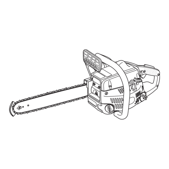
OPERATOR'S MANUAL
14 in. (356 mm) 33cc Chain Saw
Model No. UT10510, UT10510A, UT10901A, UT10901B
Your new chain saw has been engineered and manufactured to Homelite's high standard for dependability, ease of operation,
and operator safety. Properly cared for, it will give you years of rugged, trouble-free performance.
WARNING:
using this product.
Thank you for buying a Homelite chain saw.
SAVE THIS MANUAL FOR FUTURE REFERENCE
To reduce the risk of injury, the user must read and understand the operator's manual before
Advertisement
Table of Contents
Troubleshooting

Related Manuals for Homelite UT10510A


Summary of Contents for Homelite UT10510A
- Page 1 14 in. (356 mm) 33cc Chain Saw Model No. UT10510, UT10510A, UT10901A, UT10901B Your new chain saw has been engineered and manufactured to Homelite’s high standard for dependability, ease of operation, and operator safety. Properly cared for, it will give you years of rugged, trouble-free performance.
-
Page 2: Table Of Contents
IMPORTANT Servicing requires extreme care and knowledge and should be performed only by a qualified service technician. When servicing use only identical Homelite replacement parts. For safe operation, read and understand all instructions before using the chain saw. Follow all safety instructions. -
Page 3: General Safety Rules
WARNING: The warnings, labels, and instructions found in this section of the operator's manual are for your safety. Failure to follow all instructions may result in serious personal injury. Safe operation of this tool requires that you read and understand this operator's manual and all labels affixed to the tool. -
Page 4: Specific Safety Rules
ALL CHAIN SAW SERVICE, other than the items listed in the instruction manual and all maintenance, should be performed by competent chain saw service personnel. (For example, if improper tools are used to remove the flywheel or if an improper tool is used to hold the flywheel in order to remove the clutch, structural damage to the flywheel could occur and subsequently could cause the flywheel to burst.) -
Page 5: Specific Safety Rules
Refer to “Operation” later in this manual. If the saw chain still moves at idle speed after adjustment has been made, contact a Homelite Service Center for adjustment and discontinue use until the repair is made. WARNING:... -
Page 6: Symbols
Important: Some of the following symbols may be used on your tool. Please study them and learn their meaning. Proper interpretation of these symbols will allow you to operate the tool better and safer. SYMBOL NAME Safety Alert Symbol Read Your Operator’s Manual Eye, Hearing, and Head Protection SAFE-T-TIP Nose Guard No Smoking... -
Page 7: Specifications
The purpose of safety symbols is to attract your attention to possible dangers. The safety symbols, and the explanations with them, deserve your careful attention and understanding. The safety warnings do not by themselves eliminate any danger. The instructions or warnings they give are not substitutes for proper accident prevention measures. Symbol Meaning DANGER:... -
Page 8: Features
FEATURES TRIGGER RELEASE THROTTLE LOCK BUTTON CHAIN OIL FRONT HAND GUARD SAFE-T-TIP BAR MOUNTING NUTS FRONT HANDLE CHOKE LEVER CLUTCH COVER PRIMER BULB CYLINDER COVER STARTER GRIP REAR HANDLE STARTER/FAN HOUSING IGNITION SWITCH THROTTLE FUEL CAP TRIGGER Fig. 2 Page 8... -
Page 9: Operation
When making a replacement, be sure to order one of the Homelite bars listed for your saw in this operator's manual. The proper size SAFE-T-TIP nose guard comes installed on the bar. Use only guide bars that have a provision for mounting the SAFE-T-TIP. - Page 10 KICKBACK PRECAUTIONS See Figures 4 and 5. Rotational kickback occurs when the moving chain con- tacts an object at the Kickback Danger Zone of the guide bar. The result is a lightning fast, reverse reaction which kicks the guide bar up and back towards the operator. This reaction can cause loss of control which can result in serious injury.
- Page 11 ADDING OIL See Figure 7. Use HOMELITE Bar and Chain Oil. It is designed for chains and chain oilers, and is formulated to perform over a wide temperature range with no dilution required. Chain saw should use approximately one tank of oil per tank of fuel.
- Page 12 STARTING THE ENGINE: 3. Set the ignition switch to the RUN (I) position. 4. Fully press and release the PRIMER BULB 7 times. 5. Pull CHOKE lever all the way OUT to full position. 6. While squeezing both the trigger release and throttle trigger, push in the throttle lock button.
- Page 13 7. When the temperature is above 50° F, pull the STARTER GRIP until the engine attempts to start, but no more than 3 times. When the temperature is below 50° F, pull the STARTER GRIP until the engine attempts to start, but no more than 5 times. 8.
- Page 14 PREPARING FOR CUTTING PROPER GRIP ON HANDLES See Figures 16 and 17. Refer to “Specific Safety Rules – Safety Apparel” earlier in this manual for appropriate safety equipment. Wear non-slip gloves for maximum grip and protection. Hold the saw firmly with both hands. Always keep your LEFT HAND on the front handle and your RIGHT HAND on the rear handle so that your body is to the left of the chain line.
- Page 15 The carburetor will permit only limited adjust- ment of the “L” (Low Jet) and “H” (High Jet) needles. Any adjustment should be done by a Homelite Service Center. Under no circumstances should the “L” (Low Jet) and “H” (High Jet) needles be forced outside the range of adjust- ment.
- Page 16 If the chain turns at idle, turn the idle speed screw “ T ” counterclockwise to reduce the idle RPM and stop the chain movement. If the saw chain still moves at idle speed, contact a Homelite Service Center for adjust- ment and discontinue use until the repair is made. WARNING: THE SAW CHAIN SHOULD NEVER TURN AT IDLE.
- Page 17 PROPER PROCEDURE FOR TREE FELLING See Figures 23 through 27. 1. Pick your escape route (or routes in case the in- tended route is blocked). Clear the immediate area around the tree and make sure there are no obstruc- tions in your planned path of retreat. Clear the path of safe retreat approximately 135°...
- Page 18 4. Make the backcut level and horizontal, and at a mini- mum of 2 inches (5 cm) above the horizontal cut of the notch. Note: Never cut through to the notch. Always leave a band of wood between the notch and back cut (approxi- mately 2 inches (5 cm) or 1/10 the diameter of the tree).
- Page 19 REMOVING BUTTRESS ROOTS See Figure 28. A buttress root is a large root extending from the trunk of the tree above the ground. Remove large buttress roots prior to felling. Make the horizontal cut into the buttress first, followed by the vertical cut. Remove the resulting loose section from the work area.
- Page 20 OPERATION BUCKING LOGS UNDER STRESS LOG SUPPORTED AT ONE END Make the first bucking cut 1/3 of the way through the log and finish with a 2/3 cut on the opposite side. As you cut the log, it will tend to bend. The saw can become pinched LOAD FINISHING CUT or hung in the log if you make the first cut deeper than 1/3...
- Page 21 LIMBING AND PRUNING See Figure 33. Work slowly, keeping both hands on the saw with a firm grip. Maintain secure footing and balance. Keep the tree between you and the chain while limbing. Do not cut from a ladder, this is extremely dangerous. Leave this operation for professionals.
-
Page 22: Maintenance
ASSEMBLING THE BAR AND CHAIN See Figures 36 through 44. DANGER: Never start the engine before installing the guide bar, chain, drivecase cover, and clutch drum. Without all these parts in place, the clutch can fly off or explode exposing the user to possible serious injury. WARNING: To avoid serious personal injury, read and under- stand all the safety instructions in this section. - Page 23 6. Lay out the saw chain in a loop and straighten any kinks. The cutters should face in the direction of chain rotation. If they face backwards, turn the loop over. 7. Place the chain drive links into the bar groove as shown.
- Page 24 11. Replace the outer guide bar plate ensuring that the bar pin groove is at the bottom with the upper and lower edges angled away from the guide bar. 12. Replace the clutch cover and bar mounting nuts. 13. Tighten the bar mounting nuts finger tight only. The bar must be free to move for tension adjustment.
- Page 25 ADJUSTING THE CHAIN TENSION See Figures 45, 46, and 47. WARNING: Never touch or adjust the chain while the motor is running. The saw chain is very sharp. Always wear protective gloves when performing maintenance on the chain. 1. Stop the engine before setting the chain tension. 2.
- Page 26 If the cutter teeth hit hard objects such as nails and stones, or are abraded by mud or sand on the wood, have the Homelite Service Center sharpen the chain. Note: Inspect the drive sprocket for wear or damage when replacing the chain. If signs of wear or damage are present in the areas indicated, have the drive sprocket replaced by a Homelite Service Center.
- Page 27 MAINTENANCE RIGHT HAND Fig. 52 CUTTERS CAUTION: A dull or improperly sharpened chain can cause excessive engine speed during cutting which may result in severe engine damage. WARNING: Fig. 53 Improper chain sharpening increases the potential of kickback. WARNING: Failure to replace or repair a damaged chain can cause serious injury.
- Page 28 TOP PLATE FILING ANGLE See Figure 55. CORRECT 30° - file holders are marked with guide marks to align file properly to produce correct top plate angle. LESS THAN 30° – for cross cutting. MORE THAN 30° – feathered edge dulls quickly. SIDE PLATE ANGLE See Figure 56.
- Page 29 MAINTAINING THE GUIDE BAR See Figure 60. CAUTION: Make sure the chain has stopped before you do any work on the saw. Every week of use, reverse the guide bar on the saw to distribute the wear for maximum bar life. The bar should be cleaned every day of use and checked for wear and damage.
- Page 30 TIGHTEN 3/4 OF A TURN MOUNTING THE SAFE-T-TIP® NOSE GUARD See Figures 61 and 62. 1. Mount the SAFE-T-TIP on the bar nose. 2. Fit the locking rivet or tab in the recessed hole in the guide bar. 3. Tighten the screw with your finger. 4.
- Page 31 Because parts can fracture and pose a danger of thrown objects, leave repairs of the flywheel and clutch to trained Homelite Service Center personnel. CLEAN CYLINDER FINS Note: Depending on the type of fuel used, the type and...
-
Page 32: Maintenance
CLEANING THE SPARK ARRESTING MUFFLER See Figure 71. The muffler is equipped with a spark arrestor screen. A faulty spark arrestor screen can create a fire hazard. Through normal use the screen can become dirty and should be inspected weekly and cleaned as required. Always keep the muffler and spark arrestor on your saw in good condition. -
Page 33: Bar And Chain Combination
2. Clean air filter. Refer to “Maintenance – Cleaning the Air Filter” earlier in this manual. 3. Clean spark arrestor screen. Refer to “Maintenance – Cleaning the Spark Arresting Muffler” earlier in this manual. 4. Contact a Homelite Service Center for carburetor adjustment. Page 33 Chain Part Number 984296005... -
Page 34: Troubleshooting
If oil is present the chain may be dull or bar may be damaged. If no oil is on the SAFE-T- TIP, contact a Homelite Service Center. ing Chain Brake” earlier in this manual. Adjusting the Chain Tension” earlier in this manual. -
Page 35: Warranty
The equipment engine must be free from defects in material and workmanship which cause it to fail to conform with U.S. EPA standards for the first two years of engine use from the date of sale to the ultimate purchaser. Homelite Consumer Products, Inc., must warranty the emission control system on your utility/lawn/garden equipment engine for the period of time listed above provided there has been no abuse, neglect, or improper maintenance of your utility/lawn/garden equipment engine. -
Page 36: Parts Ordering/Service
OPERATOR'S MANUAL 14 in. (356 mm) 33cc Chain Saw Model No. UT10510, UT10510A, UT10901A, UT10901B WARNING: The engine exhaust from this product contains chemicals known to the State of California to cause cancer, birth defects or other reproductive harm. CALIFORNIA PROPOSITION 65 For product information, technical help, dealer locations or parts ordering information visit our website at: www.homelite.com.