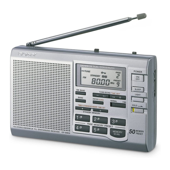
Sony ICF-SW35 Service Manual
Fm stereo/sw/mw/lw pll synthesized receiver
Hide thumbs
Also See for ICF-SW35:
- Manual (3 pages) ,
- Specifications (2 pages) ,
- Operating instructions (2 pages)
Table of Contents
Advertisement
SERVICE MANUAL
Ver 1.0 2000. 03
Circuit system
FM: Super heterodyne
LW/MW/SW: Dual conversion super heterodyne
Frequency range
FM: 76.00 - 108.00 MHz
87.50 - 108.00 MHz*
1
SW: 2250 - 26100 kHz*
2
3850 - 26100 kHz*
3
MW: 530 - 1710 kHz
530 - 1620 kHz
LW: 150 - 285 kHz
Speaker
Approx. 66 mm (2
in.) diameter, 8 Ohms
1/8
Maximum output
240 mW (at 10 % harmonic distortion)
Output
i (headphones) jack (ø3.5 mm stereo mini jack)
16 Ohms
Power requirements
DC 4.5 V, three R6 (size AA) batteries
External power source
DC IN 4.5 V
Battery Life (approximate hours)
Sony R6
(size AA)
FM reception
17
SW reception
12
LW/MW reception
12
SPECIFICATIONS
Sony LR6
alkaline
(size AA)
46
33
33
ICF-SW35
Dimensions
Approx. 168
106
35 mm (W H
(6
4
1
in.) incl. projecting parts
5/8
1/4
7/16
Mass
Approx. 405 g (14.3 oz) incl. batteries
Supplied Accessories
Carrying case (1)
Short wave guide (1)
Design and specifications are subject to change without
notice.
The AC power adaptor's operating voltage varies
depending upon the country in which it is sold.
Buy the AC power adaptor in the country you intend
to use it.
Your Sony dealer may not handle all of the above listed
optional accessories. Please ask your dealer for detailed
information on the optional accessories available in your
country.
*
1
Italy, Saudi Arabia and Malaysia
*
Countries except for Italy
2
3
*
Italy only
FM STEREO/SW/MW/LW
PLL SYNTHESIZED RECEIVER
– 1 –
US Model
Canadian Model
AEP Model
E Model
D)
Advertisement
Table of Contents

Related Manuals for Sony ICF-SW35


Summary of Contents for Sony ICF-SW35
- Page 1 (headphones) jack (ø3.5 mm stereo mini jack) 16 Ohms Your Sony dealer may not handle all of the above listed Power requirements optional accessories. Please ask your dealer for detailed DC 4.5 V, three R6 (size AA) batteries...
-
Page 2: Table Of Contents
Notes on Chip Component Replacement TABLE OF CONTENTS Never reuse a disconnected chip component. Notice that the minus side of a tantalum capacitor may be 1. GENERAL damaged by heat. Operating the Radio ..............3 Setting the Standby Time ............5 Setting the Sleep Timer ............ - Page 3 SECTION 1 This section is extracted from instruction manual. GENERAL – 3 –...
- Page 4 – 4 –...
- Page 5 – 5 –...
-
Page 6: Disassembly
SECTION 2 DISASSEMBLY Note : Follow the disassembly procedure in the numerical order given. 2-1. CABINET (REAR) 1 P 3x14 4 claw 5 cabinet (rear) 2 P 3x14 3 claws 2-2. MAIN BOARD 2 P 3x14 1 Removal the solder. 6 MAIN board 5 CN1 3 claw... -
Page 7: Micon Board
2-3. MICON BOARD 1 BTP 2x8 2 BTP 2x8 3 MICON board – 7 –... -
Page 8: Electrical Adjustments
SECTION 3 ELECTRICAL ADJUSTMENTS FM SECTION 0 dB = 1 µV • Connecting Digital Voltmeter (FM, SW, MW and LW) Setting: digital BAND switch: FM voltmeter VOLUME: MAX ATT: OFF TONE: MUSIC (VT) FM RF signal telescopic generator antenna terminal •... -
Page 9: Fm Vco Adjustment
FM VCO ADJUSTMENT • Connecting Frequency counter frequency FM RF signal telescopic counter generator antenna terminal 33 k 1 F/50V 0.01 F 98MHz, non-modulation FM VCO ADJUSTMENT Output level: 0.1v(100dB) Reading on Frequency counter 76 kHz ± 200 Hz Adjustment Part Adjustment Location: FM TRACKING ADJUSTMENT AM IF ADJUSTMENT... -
Page 10: Diagrams
SECTION 4 DIAGRAMS 4-1. IC PIN DESCRIPTION • IC201 uPD17072GB-017-1A7 (SYSTEM CONTROL, LCD DRIVER) Pin No. Pin Name Pin Description EEPROM CS control output POWER Power supply (for signal ) start output H: Radio ON L: Radio OFF BAR/ROD Antenna switch output H: BAR ANTENNA L: ROD ANTENNA MUTE... -
Page 11: Block Diagram
ICF-SW35 4-2. BLOCK DIAGRAM – 11 – – 12 –... -
Page 12: Printed Wiring Board - Main Section
ICF-SW35 4-3. PRINTED WIRING BOARD — MAIN SECTION — (Page 18) ANT1 (US) MICON FM/SW BOARD MAIN BOARD TELESCOPIC C238 ANTENNA w VOL (FM ANT) BPF1 (AM/FM) (GND) JC13 JC12 (TUNE) C101 C102 JC21 (GND) MUSIC JC10 TONE (LCH) NEWS..MUSIC... -
Page 13: Schematic Diagram - Main Section
ICF-SW35 4-4. SCHEMATIC DIAGRAM — MAIN SECTION — • Refer to page 21 for IC Block Diagrams. (Page 19) (Page 20) • Waveform 0.1V/div 0.2 sec/div 4.4Vp-p 1.78MHz – 15 – – 16 –... -
Page 14: Printed Wiring Board - Micon Section
ICF-SW35 4-5. PRINTED WIRING BOARD — MICON SECTION — MICON BOARD (US) MAIN BOARD • Semiconductor LCD201 Location (Page 13) LIQUID CRYSTAL DISPLAY PANEL Ref. No. Location D201 D202 D203 R268 D204 C235 R270 D205 C-10 JC217 D206 Q206 Q207... -
Page 15: Schematic Diagram - Micon Section
ICF-SW35 4-6. SCHEMATIC DIAGRAM — MICON SECTION — • Refer to page 21 for IC Block Diagrams. (Page 15) (Page 15) Note on Schematic Diagram: • All capacitors are in µF unless otherwise noted. pF: µµF 50 WV or less are not indicated except for electrolytics and tantalums. -
Page 16: Exploded View
SECTION 5 EXPLODED VIEW • IC Block Diagrams NOTE: • The mechanical parts with no reference • Accessories and packing materials are given in • Color Indication of Appearance Parts number in the exploded views are not supplied. the last of this parts list. Example : IC1 CXA1238S •... -
Page 17: Electrical Parts List
SECTION 6 MAIN ELECTRICAL PARTS LIST NOTE: • Due to standardization, replacements in • Items marked “*” are not stocked since When indicating parts by reference the parts list may be different from the they are seldom required for routine service. number, please include the board. - Page 18 MAIN Ref. No. Part No. Description Remark Ref. No. Part No. Description Remark 1-110-563-11 CERAMIC CHIP 0.068uF 8-719-988-61 DIODE 1SS355TE-17 1-115-156-11 CERAMIC CHIP 8-719-988-61 DIODE 1SS355TE-17 1-126-157-11 ELECT 10uF 8-719-977-40 DIODE UDZ-TE-17-13B 1-115-156-11 CERAMIC CHIP 8-719-988-61 DIODE 1SS355TE-17 1-115-156-11 CERAMIC CHIP 8-719-988-61 DIODE 1SS355TE-17 1-164-505-11 CERAMIC CHIP 2.2uF...
- Page 19 MAIN Ref. No. Part No. Description Remark Ref. No. Part No. Description Remark 1-402-815-11 COIL (WITH CORE) (FM RF) 1-216-837-11 METAL CHIP 1/16W 1-412-925-11 INDUCTOR 68nH 1-216-857-11 METAL CHIP 1/16W 1-406-786-11 COIL, FM (OSC) 1-216-827-11 METAL CHIP 3.3K 1/16W 1-412-963-11 INDUCTOR 100uH 1-216-845-11 METAL CHIP 100K...
- Page 20 MAIN MICON Ref. No. Part No. Description Remark Ref. No. Part No. Description Remark 1-216-833-11 RES-CHIP 1/16W A-3663-471-A MICON BOARD, COMPLETE 1-216-849-11 METAL CHIP 220K 1/16W *********************** 1-216-829-11 METAL CHIP 4.7K 1/16W 1-216-057-00 METAL CHIP 2.2K 1/10W 1-792-459-11 CABLE, FLAT (FFC) 18P 1-216-797-11 METAL CHIP 1/16W 3-042-894-01 CASE (LCD)
- Page 21 MICON Ref. No. Part No. Description Remark Ref. No. Part No. Description Remark < CONNECTOR > < TRANSISTOR > * CN201 1-691-077-21 HOUSING, CONNECTOR 18P Q201 8-729-220-93 FET 2SK209-G Q202 8-729-402-32 TRANSISTOR 2SD1819A-R < DIODE > Q203 8-729-220-93 FET 2SK209-G Q204 8-729-423-52 TRANSISTOR 2SC3931-C D201...
- Page 22 ICF-SW35 MICON Ref. No. Part No. Description Remark Ref. No. Part No. Description Remark R243 1-216-845-11 METAL CHIP 100K 1/16W S215 1-692-444-11 SWITCH, KEY BOARD (SW BAND) R244 1-216-845-11 METAL CHIP 100K 1/16W S216 1-553-977-00 SWITCH, SLIDE (HOLD .) R245...