Advertisement
Table of Contents
IMPORTANT: READ SAFETY RULES AND INSTRUCTIONS CAREFULLY
This Service Manual is not a substitute for the Operator's Manual. You must read, understand
and follow all of the directions in this manual as well as the Operator's Manual before working
on this power equipment.
CUB CADET LLC, P.O. BOX 361131, CLEVELAND, OH 44136-0019
PRINTED IN USA
Service Manual
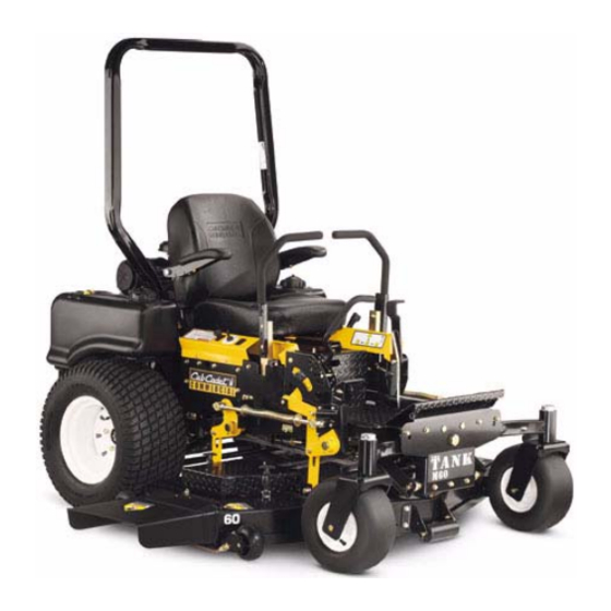
Cub Cadet M48 Tank
FORM NO.769-00966
(11/2003)
Advertisement
Table of Contents

Related Manuals for Cub Cadet M48 Tank


Summary of Contents for Cub Cadet M48 Tank
-
Page 1: Service Manual
This Service Manual is not a substitute for the Operator’s Manual. You must read, understand and follow all of the directions in this manual as well as the Operator’s Manual before working on this power equipment. CUB CADET LLC, P.O. BOX 361131, CLEVELAND, OH 44136-0019 PRINTED IN USA Cub Cadet M48 Tank FORM NO.769-00966... -
Page 3: Table Of Contents
TABLE OF CONTENTS M48 Tank ... 1 About this Section ... 1 Changes for ‘03 and ‘04 ... 1 Drive System Adjustment ... 1 Hydro Pump Testing... 4 Hydro Pump Replacement ... 6 Hydro Pump Motor Replacement ... 10 Brake Linkage Adjustment ... 13 M72 Tank ... -
Page 5: M48 Tank
ABOUT THIS SECTION: The M48 is part of the Cub Cadet Commercial Tank Series. The 2004 model year M48 is very similar to The 2001 model year Tank. Earlier versions of this machine have been covered in the “2001 Cub Cadet Commercial Technical Handbook”: Form #770-... - Page 6 M48 Tank 3.5. For complete brake adjustment procedures, refer to the “Brake Adjustment” section of this manual. For the purpose of tracking, insure that the brake linkage bellcranks and rods are well lubricated, not damaged, and work as intended. See Figure 3.5.
- Page 7 STOP BOLT Figure 3.17 NOTE: The clamp bolts for the lap bar mounting handle can be used to adjust the amount of force required to move the lap bars into or out of the neutral slot. M48 Tank CLAMP BOLTS...
-
Page 8: Hydro Pump Testing
TESTING HYDRO PUMP OUTPUT NOTE: The log splitter hydraulic test kit is used for this set of flow and pressure tests. 4.1. Safely lift and support the rear of the M48. 4.2. If the cutting deck is currently on the unit, remove it. - Page 9 Top it up if necessary. 4.22. Continue to operate the drive system to warm-up the hydraulic fluid. NOTE: Performing the test with cold fluid will make a significant difference in the flow readings obtained. The test will not be valid. M48 Tank...
-
Page 10: Hydro Pump Replacement
4.26. Subtract the 1,100 PSI flow reading from the 300 PSI flow reading. The resulting figure is called “flow droop”. 4.27. Interpretation: flow droop greater than 1.5 GPM 4.28. Within the two year Cub Cadet Commercial war- CONTROL CONSOLE INSET: 3600 RPM SPINNING 4.29. - Page 11 WARNING: Hot hydraulic fluid can cause seri- ous burns. WARNING: Release of pressurized hydraulic fluid can cause serious of fatal injury. M48 Tank ROD END BOLT...
- Page 12 M48 Tank 5.14. Open the relief valve on the hydro pump that is to be tested. This will relieve any residual hydraulic pressure. See Figure 5.14. RETURN LINE FEED LINE OPEN ELBOW RELIEF VALVE Figure 5.14 5.15. Confirm that the hydraulic pressure has been relieved by rotating the brake drum / hub assem- bly.
- Page 13 AND PLUGGED Figure 5.25 5.26. Carefully lower and remove the hydro pump. If it is to be returned to Cub Cadet, remove the yel- low plugs and allow it to drain completely before packing and shipping it. 5.27. Inspect all of the fittings and O rings prior to installation in the replacement pump.
-
Page 14: Hydro Pump Motor Replacement
M48 Tank 5.39. Install the wheels, lower the TANK to the ground, and test run it in a safe area. Make any neces- sary adjustments before installing the cutting deck. REPLACING THE HYDRO MOTOR 6.1. If the cutting deck is currently on the unit, remove it. - Page 15 6.15. Lift the motor slightly and carefully pull it out far enough to remove the motor plate from the end of the four bolts. See Figure 6.15. MOTOR SPACERS NOTE: The hydro motor weighs nearly 50 lbs. M48 Tank MOUNTING BOLTS Figure 6.13 MOTOR PLATE Figure 6.15...
- Page 16 M48 Tank 6.16. Withdraw the hydro motor, along with the three motor spacers, and place them gently on a work bench. See Figure 6.16. Figure 6.16 6.17. If the brake is to be removed, remove the clip that holds the brake arm on the splined shaft, and mark the location of the brake arm on the splined shaft.
-
Page 17: Brake Linkage Adjustment
7.5. Rotate each wheel to confirm that the brakes are not dragging or binding. 7.6. Remove the rear wheels using a 3/4” socket. NOTE: It may be necklaces to set the parking brake while loosening the lug nuts. M48 Tank... - Page 18 M48 Tank 7.7. Loosen the jam nut that locks the shoulder nut in position on the brake connector rod using a 9/16” wrench and a 3/4” wrench. See Figure 7.7. SHOULDER NUTS JAM NUTS BRAKE CONNECTOR RODS Figure 7.7 7.8.
- Page 19 7.20. Apply the parking brake. The gap between the bottom edges of the brake bracket and the cross member that it rests against in the released posi- COLLAR tion should be roughly 1 3/4”. See Figure 7.20. BRAKE BEARING M48 Tank ADJUST HEAVY LIGHT SPRING CONTACT HERE Figure 7.19...
-
Page 20: M72 Tank
M48 Tank 7.21. Release the parking brake. 7.22. The brake bracket should draw up against the frame cross member. If this reaction is not con- sistent, tighten the shoulder nut slightly. There should be roughly 1 1/2” between the head of the shoulder nut and the brake bracket when the brakes are applied. - Page 21 See Figure 8.4. Figure 8.4 8.5. Heavier hardware connects the deck to the hangers. See Figure 8.5. Figure 8.5 8.6. Heavier front pivot bar and wider front track. See Figure 8.6. Figure 8.6 M48 Tank...
- Page 22 M48 Tank 8.7. The track at the rear has also increased. Extra brackets have been added to the frame to step the hydro motors out. See Figure 8.7. Figure 8.7 8.8. To enable the brake linkage to reach the reposi- tioned hydro motor, the rear brake arm assem- blies have been doubled-up on each side.
-
Page 23: Other Tank Features
OTHER TANK FEATURES 9.1. Honda Power is offered on the M48-HN and M54-HN. The M48-HN has a 20 H.P. Honda V- twin engine. The M54-HN has a 24 H.P. Honda V-twin. See Figure 9.1. Figure 9.1 9.2. ROPS is offered on the M60-KW (Kawasaki) and M60-KH (Kohler). - Page 24 M48 Tank 9.6. 1/4” increments on the height adjuster, with foot assist deck lift. See Figure 9.6. Figure 9.6 9.7. The deck belt release operates in a vertical plane. It can be tensioned with foot pressure, and the rear wheel does not interfere with its travel.
- Page 25 9.14. The trailing edge of the discharge opening has been swept back, and the bar that prevents foot penetration has been modified. Both changes improve strength and airflow. See Figure 9.14. Figure 9.14 M48 Tank...
- Page 26 M48 Tank 9.15. A guiding baffle near the rear of the opening helps direct the clippings out from under the deck. See Figure 9.15. Figure 9.15 9.16. The addition of a “California Gap” at the leading edge also improves airflow, and products the...
-
Page 27: Kohler Efi
Fuel return line Figure 10.3 10.4. The fuel lines from each tank Tee into a single line that feeds the fuel pump. See Figure 10.4. From left tank To pump Figure 10.4 M48 Tank From right tank From pump to filter... - Page 28 M48 Tank 10.5. The return lines each lead back to the tank from a tee fitting just beneath the tee fitting for the fuel feed lines. The return fuel comes from the fuel pressure regulator. NOTE: If one branch of the return line becomes crushed, kinked, or blocked, a disproportionate amount of fuel will return the the opposite tank.
- Page 29 10.10. After the filter, the fuel reaches the fuel rail. The fuel rail feeds the injectors. See Figure 10.10. M48 Tank From pump Fuel filter...
-
Page 30: Efi Controls
M48 Tank Cap for shrader valve electrical connection injector Fuel injector Figure 10.10 10.11. The shrader valve can be used for checking fuel pressure. Fuel pressure readings obtained at the shrader valve can help pin-down problems with the fuel pump or the fuel pressure regulator. - Page 31 It is very durable, but there are some rules to follow in order to avoid damage to the ECU: • If you diagnose a faulty ECU, do not replace it without calling Cub cadet Technical Support for specific handling instructions. • Previously mentioned: do not use a conventional test light to look for power in the engine control circuit.
- Page 32 M48 Tank • Do not connect a battery charger to the TANK with the key switch turned on. • The ECU requires at least 7.0 volts to function. • If the battery goes dead, or is disconnected, the adaptive memory in the ECU will be cleared. It...
- Page 33 A steadily declining voltage that recovers from a throttle blip without fluctuating may indicate an improperly positioned TPS. tem used on the Kohler engine found on the TANK. Complete diagnostic and service instruc- tions can be found in the Kohler CH26 manual, section 5B. M48 Tank...