Table of Contents
Advertisement
Quick Links
Advertisement
Table of Contents

Related Manuals for Robin RGD500


Summary of Contents for Robin RGD500
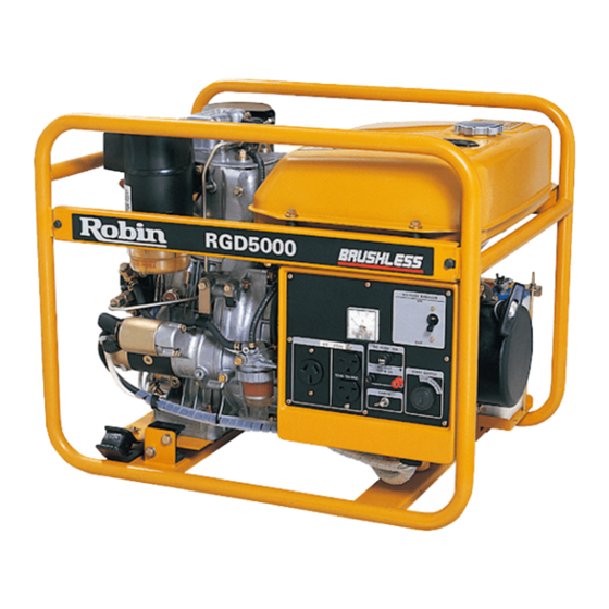
- Page 1 MAN,UAL Model RGD5000 Generator PUB-GS1187 Rev. 8198...
-
Page 2: Table Of Contents
CONTENTS nt/e section Page ....................... SPECIFICATIONS ................... PERFOMANCE CURVES ....................2-1 MODEL RGD5000 ......................2-2 DC OUTPUT ........................FEATURES ..................GENERAL DESCRIPTION ....................4-1 EXTERNAL VIEW ....................4-2 CONTROL PANEL ...... 4-3 LOCATION of SERIAL NUMBER SPECIFICATION NUMBER ................CONSTRUCTION AND FUNCTION 5-1 CONSTRUCTION .................... - Page 3 Section Tile ............... 10-3 DISASSEMBLY PROCEDURES ................10-4 ASSEMBLY PROCEDURES ..10-5 CHECKING. DISASSEMBLY REASSEMBLY CONTROL .................... TROUBLESHOOTING ....................OUTPUT 11 -1 NO AC ........... 11-2 AC VOLTAGE THIGH OR TOO LOW ..BUTTHE 11-3 VOLTAGE NORMALAT NO-LOAD. LOAD CANNOT APPLIED ....................
-
Page 4: Specifications
Model RGD5000 Exciting, Brushless, Self 2-Pole, Single Phase JYPe 60 Hz Frequency 5000 W Maximum O u t p u t Rated Output 4500 W 12OV/24OV Current 37.5 A 37.5N18.814 Power Factor DC Output 12 V-8.3 A (100 W) Regulator Voltage Type Condenser... -
Page 5: Perfomance Curves
2. PERFOMANCE CURVES 2-1 MODEL RGD5000 ....Output Max. 5000 ....Output Rated 4500 W ....Frequency = 6 0 ......Voltage 120 V CURRENTO ....Output Max. 5000 W .... Output Rated 4500 W ....Frequency 60 Hz ...... Voltage 120 Vl24OV 2-2 DC... -
Page 6: Features
3.FEATURES 3-1 BRUSHLESS ALTERNATOR Newly developed brushless alternator eliminates troublesome brush maintenance. 3-2 EASY STARTING Light pull recoil starter accompanied with automatic decompression system makes the new series generators even easier in starting than gasoline engine generators. 3-3 QUIET OPERATION The new RGD series generator provides quiet operation by means The superb design of intake-exhaust system. -
Page 7: General Description
4.GENERAL DESCRIPTION 4-1 EXTERNAL VIEW Rocket cover Air cleaner ACreceptack gauge Tank cap Fuel Muffler... -
Page 8: Control Panel
4-2 CONTROL PANEL RGD5000 : 60HZ-l20V, 60Hz-l2OV/240V TYPE Voltmeter Full power switch Earth terminal output terminal... -
Page 9: Location Of Serial Number And Specification Number
4-3 LOCATION of SERIAL NUMBER and SPECIFICATION NUMBER Serial number and specification number are stamped on the LABEL (MODEL NAME) stuck the side wall control box. NOTE : Always specify these numbers when inquiring about the generator or ordering spare parts in order to get correct parts and accurate service. -
Page 10: Construction And Function
5CONSTRUCTION AND FUNCTION " !j-lCONSTRUCTlON Mount rubber Driving shaft Starter pu"ey Stator Generator base bolt Ball bearing Adapter Fig. 5-1 5-2 FUNCTION 5-2-1 STATOR The stator consists of a laminated silicon steel sheet core, a main c o i l and a condenser coil which are wound in the core slots. - Page 11 5-2-2 CONDENSER One or two condensers are installed in the con- trol box and are connected to the condenser coil of the stator. These condensers and condenser coil regulate the output voltage. 5-2-3 ROTOR The rotor consists of a laminated silicon s t e e l sheet core and a field coil which is wound over the core.
- Page 12 5-24 DC FUSE DC fuse mounted on the con- (1) The 10 ampere trol panel protects whole circuit from get- ting damage by overload or short circuit. (2) The 15 ampere fuse in the control box pro- tects the diode rectifier from getting damage by reverse connection to the battery.
- Page 13 5-2-6 RECEPTACLE and AC PLUG (STD.SPEC.) used for taking AC output power from the generator. A total of six kinds These are receptacles, each varying in rated voltage and current from another, are used. Each model has at least one receptacle to deliver the rated generator output.
-
Page 14: Generator Operation
PERMANENT MAGNET STATOR INITIAL EXCITATION COIL FIELD APPLIANCE " " " " " " " fig, 5-3-1GENERATlON NO-LOAD VOLTAGE (1) When the generator starts running, the permanent magnet built-in to the rotor generates 3 to of AC voltage inthe main coil and condenser coil wound on the stator. (2) As one or two condensers are connected to the condenser coil, the small voltage at the condenser coil generates a minute current which flows through the condenser coil. - Page 15 (Dual FULL POWER SWITCH Voltage Type) 5-34 The full power switch is provided for the dual voltage type to take out the full rated power from one receptacle in each voltage. Fig. 5-10 Fig. 5-11 LOWER VOLTAGE Switch VOLTAGE HIGHER RECEPTACLE RECEPTACLE No output can Rated...
- Page 16 Two main coils are wound over stator core. Each main coil outputs half the rated power at the lower voltage (11OV or 120V). These main coils are wound to be in the same phase. The full power switch reconnects these main coils in parallel or in series. Fig.
-
Page 17: Safety Precautions
6. SAFETY PRECAUTIONS 1. Use extreme caution near fuel. A constant danger of explosion or fire exists. Do not fill the fuel tank while the engine is running. Do not smoke or use opern flame near the fuel tank. Be careful not to spill fuel when refueling. spilt, wipe it and let dry before starting the engine. - Page 18 be done by it. Generally, the power rating of electrical appliance indicates the amount of work that can The electric power required for operating an electrical appliance is not always equal to the output watt- age of the appliance. The electrical appliances generally have a label showing their rated voltage, fre- quency, and power consumption (input wattage).
- Page 19 (5) Appliances without any indication as to power consumption Some appliances have no indication as to power consumption; but instead the work load (output) indicated. In such a case, power consumption is to be worked out according to the numerical formula mentioned below.
- Page 20 NOTES : Wring between generator and electrical appliances I . Allowable current of cable Use a cable W h an allowable current that is higher than the rated input current of the load (electrica appliance). If the input current is higher than the allowable current the cable used, the cable will it out.
-
Page 21: Measuring Procedures
8. MEASURING PROCEDURES MEASURING INSTRUMENTS 8-1-1 “Dr. ROBIN” GENERATOR TESTER The “Dr. Robin” generator tester is exclusively designed for fast, easy diagnosis and repair of Robin generators. The “Dr. Robin” has the follow- ing features : (1) Functions of voltmeter, frequency meter, meggertester, capacitance meter and circuit tester are combined in one unit. - Page 22 8-1-2 INSTRUMENTS (1 ) VOLTMETER AC voltmeter is necessary. The approximate AC voltage ranges of the voltmeters to be used various types generators are as follows: to 150V : Type with an output voltage of 11 or 120V to 300V : Type with an output voltage 220, 230 or 240V to 15OV, 0 to 330V : Dual voltage type...
- Page 23 CIRCUITTESTER Used for measuring resistance, etc. TESTER (5) MEGGER Used for measuring generator insulation re- sistance. Select one with testing voltage range of 500V. Fig. TACHOMETER Use the contactless type tacho meter. Fig. 8-7 2 0 -...
-
Page 24: Ac Output Measuring
8-2 AC OUTPUT MEASURING TO AC RECEPTACLE Fig. 8-8 Use a circuit like the shown in Fig.8-8 for measuring AC output. A hot plate or lamp with a power factor of be used as a load. Adjust the load and rpm. and check that the voltage range as specified in Table 8-2 at the rated amperage and rated rpm. -
Page 25: Measuring Insulation Resistance
8 4 MEASURING INSULATION RESISTANCE "Dr. Robinngenerator tester in megger tester mode or use a megger tester to check the insula- tion resistance. Connect a megger tester to one of receptacle output terminals and the ground ter- minal, then measure the insulation resistance. An insulation resistance of 1 megohm or more is nor- mal. - Page 26 CONTROL PANEL Measure the insulation resistances between the live parts and the grounded parts. fig. 8-13 Any part where the insulation resistance is less than 1 MQ faulty insulation, and may cause electric leakage and electric shock. Replace the faulty part.
-
Page 27: Checking Functional Members
9.CHECKING FUNCTIONAL MEMBERS 9-1 VOLTMETER Check the the voltmeter if is turned by apply- ing specific voltage. Voltmeter cannot be checked with circuit tester because its resistance is too large. 9-2 AC RECEPTACLES Using "Dr. Robinnor a circuit tester, check conti- nuity between the terminals at the rear of the AC receptacles while the receptacle is mounted... -
Page 28: Stator
9-4 STATOR Disengage connectors the wires from stator and check the resistance between wires with a fol- "Dr. Robin" or a circuit tester refering to the table. lowing Fig. Winding Condenser Winding Specification MODEL Black Blue White Yellow / Yellow Voltage 120v RGD5000... -
Page 29: Rotor Assembly
9-5 ROTOR ASSEMBLY coil at the terminals. Using "Dr. Robin" tester, measure resistance of the (1 ) field Circuit ( Q ) MODEL RGD5000 RESISTANCE 1.6 Q Tble. NOTE Because a diode is soldered to the coil ends at the terminals, resistance may be measured only when tester probes touche the terminals in one combination of polarity merefore, if no resisfance reading appears, try cbecking in reverse polarity. -
Page 30: Condenser
9dCONDENSER Use a "Dr. Robin" in capacitance meter mode to check the capacity of condensers. Be sure t o discharge condensers short- NOTE : condenser leads each other before checking their capacitance, or the accurate reading cannot be obtained. NORMAL CAPACITY CONDENSER Fig. - Page 31 Checkina table for analoaue circuit tester. Apply black (minus) needle the circuit tester Analogue circuit tester Brown Brown Orange B r o w m i t e Brown No continuity No continuity Continuity Apply needle red (plus) the circuit tester Orange Continuity Continuity Continuity...
-
Page 32: Disassembly And Assembly
10. DISASSEMBLY AND ASSEMBLY 10-1 PREPARATION and PRECAUTIONS to memorize the location of individual parts when disassembling the generator so that the 1) Be sure generator can be reassembled correctly. Tag the disassembled part with the necessary information to facilitate easier and smoother reassembly. 2) For more convenience,divide the parts into several groups and store them in boxes. - Page 33 10-3 DISASSEMBLY PROCEDURES Step Part remove Remarks Description Necessary tool Fuel Tank (1) Discharge fuel from the tank. Turn the fuel cock to ( S ) . close 2. Disconnect the rubber pipe from the mm spanner not lose t h e gasket.
- Page 34 Part to remove Battery (1) Remove battery cable from battery. B e careful not to short. (Only electric Remove the negative side cable f i r s t , starter then the positive side. type) (2) Remove battery from battery base. spanner or Remove the nuts that fasten the...
- Page 35 Part to remove Description Remarks Control Box Take off the bushing from the bottom Press the upper end of the control box. pull out the bushing. Fig. 10-6 (2) Take out the grommet from the bottom face of the control box. Fig.
- Page 36 P a n to remove Description Remarks Nexesarytwl Remove the control box from the frame. Control Box 10 mm spanner or ..64Washer.. 3pcs. box spanner ..6 4 b o l t . . 3pcs. Fig. 10-9 Remove side plate A. Pipe Frame .
- Page 37 Part remove Remarks Necesrarytod Description Be caref'd to Pipe Frame (3) Lift the generator with a chain block keep and dismount from the frame. the belt i n place. Fig. (See 10-1 Fig. 10-1 7 Remove engine base, generator base, and mount rubbers from frame.
- Page 38 Description Remarks Part remove Necessary t o o l spanner or Recoil Starter (1) Remove recoil starter from rear cover. bolt 4 pes. spanner Fig. 10-13 (1) Take off the through bolt and remove careful not to lose Rear Cover spanner or pulley and spacer from rotor the key at removing socket wrench...
- Page 39 Step Part remove Description Remarks Necessary tool (2) Take off the rear cover. Remove the four bolts which fasten spanner or the rear cover to the adapter of the box spanner engine..6 4 b o l t .
- Page 40 Neasssrytoal Description Remarks Stator (1) Remove support ring. Remove the four bolts which fasten mm socket the stator to the rear cover. 2. Insert a small hook into the hole inside of the support ring and pull it out..@BOLT 4 p a .
- Page 41 part to Remarks remove Description Necetrarytool mm spanner ROTOR Insert the rotor-puller shaft into rotor, and tighten the rotor-puller bolt until the rotor comes loose. If the special tool is unavailable, take the following instructions to remove the rotor. mtic Lightly strike the rotor core with plastic Never strike on the c o i l .
-
Page 42: Assembly Procedures
1 0 4 ASSEMBLY PROCEDURES 10-4-1 FRONT PROTECTOR amd FRONT COVER (1) Aligh the driving shaft with the faucet joint of the flywheel and install lO@x30mrnbolt 4pcs. p c s . # spring washer. 68.6 N-m 700 kg-cm 39.8 5 0 . 6 ft-lb (2) Install the adapter in the blower housing, making sure that its flat side is down and its fuel filter mounting boss on the air cleaner side. - Page 43 10-4-3 STATOR and REAR COVER jig so that grooves on the (1) Set the stator on the stator side match with the grooves of the jig. At the same time, be sure to set the stator on the jig so that the lead wires direct to the win- dow of rear cover.
- Page 44 The dimensions of the stator bolts are shown in Table 10-1. Tale. 10-4-4 REAR COVER (1) Attach the bush over the lead wires drawn out from the rear cover. Press the bush and into the window of the rear cover. (See Fig. 10-30.) Fig.
- Page 45 Fix the rear cover to the adapter with four ( 3 ) bolts, spring washer, and washer. 6 @ x 2 5 m m b o l t 4pcs. washer. pcs. spring washer. pcs. Tightening torque 5.9 N-m 60 k - 4 .
- Page 46 (4) Tighten the through bolt with a box wrench or a spanner. If an impact wrench is avail- able, use it. 300 kgcm 17.4 21.7 ft-lb Attach the RECOIL STARTER to REAR COVER. x 8 mm flange bolt. . 4 pcs Tightening torque kg-cm...
- Page 47 (2) Attach the engine base to the bottom of the engine. (See Fig. 10-37.) x 50 mm flange bolt pcs. . 4 pcs. NOTE : Insert the bolts from h e bottom side of the engine base. 140 kgcm mount Engine mount Engine holes...
- Page 48 8 @ ~ 2 5 m m b o l t 2pcs. lightening torque 11.8 13.7 N-m kgcm 10.1 ft-lb NOTE : When tightening the nuts and bolts, slightly lift the engine and alternator assembly so that the weight is not applied to the mount rubbers the stoppers to (5) Attach the frame.
- Page 49 (6) Attach side plate A to frame. x 10 mm bolt.. pcs. toque lightening Attach fuel tank mount rubbers to side plates. The nuts for mount rubbers are welded to side 5.9 N-m 3 . 9 plates. 60 kgcm 4 . 3 ft-lb p c s .
- Page 50 (2) Connect the wires drawn out from the stator the wires from the control box. Connect the oil sensor wires at the same time. Connect the wires of the NOTE : same color. (3) Press the upper end of the bushing into the bottom window of the control box.
- Page 51 10-4-8 BAlTERY (1) Attach ttach the battery base to the frame. 6cpxlOmmbolt 2pcs. 3 . 9 5 . 9 60 kg-cm ft-lb (2) Mount the battery on the battery base, and it with battery bolts and a battery angle. Tightening torque (See Fig.
- Page 52 10-4-9 FUEL TANK (1) Connect fuel pipe 29 complete and rubber pipe (6 mm inside diameter, 12 mm outside diameter, 170 mm long) to the fuel tank. a) Connect the rubber pipe and fasten with the hose clamp (1 0.5 rnm inside diameter).
- Page 53 (2) Mount the fuel tank on the mount rubbers attached to the side plates. nut. pcs. Tightening torque spring washer. . 4 pcs. 11.8 13.7 140 kg-cm 10.1 ft-lb (3) Connect the fuel pipe. a) Install the fuel filter assembly on the boss on the side of the adaptor (generator). 65 mm bolt.
- Page 54 10-5-2 DISASSEMBLY from Remove the control panel the control box. Regulator screw pcs. (2) Disconnect the connectors on the wires to de- tach the control panel and box. (3) Remove the regulator, oil sensor unit, condens- ers and diode rectifier from the control box.
-
Page 55: Troubleshooting
11 .TROUBLESHOOTING 11-1 NO AC OUTPUT -1-1 CHECKING STATOR Remove control panel and disconnect black, blue, red, and white wires at the connectors. Measure the resistance between terminals on stator leads. (See Fig. 11-1 .) Refer to Table for normal resistance. If sta- 11 -1 tor is faulty, replace with a new one. - Page 56 11-1-3 CHECKING OF ROTOR (1) CHECKING FIELD COIL Remove rem cover and startor. Unsolder the coil from the terminal on the rotor. (See Fig. 11 -3.) Fig. 11-3 Measure the resistance of field coil with a circuit tester. (See Fig. 11 -4.) [ Remedy ] MODEL...
- Page 57 Measure the resistance o f surge absorber connected to the diode holder. Normal resistance is Measure the resistance o f surge absorber connected to the diode holder. Remedy J the magnetic force of rotor magnets i s weak, or the surge absorber is not good, replace rotor 1.
-
Page 58: Range Of Applications
11-3 AC VOLTAGE NORMAL AT NO-LOAD, BUT THE LOAD CANNOT BE APPLIED. 11-3-1 CHECK THE ENGINE SPEED. If the engine speed is low, adjust it to the rated r.p.m. 'Refer to Step 11 -2-1 for engine speed adjustment. 11-3-2 CHECK THE TOTAL WATTAGE OF APPLIANCES CONNECTED THE GENERATOR. - Page 59 OUTPUT 1 1 4 1 1 4 1 CHECK THE AC OUTPUT. Check the generator by following Step 1 1 -1 -1 through Step 11 -1 -3. 1 1 4 2 CHECK THE DC FUSE. Check the fuse in the fuse holder. If the fuse is blown check for the cause of fuse blowing, and then replace with a new one.
- Page 60 " " _ CONlRO& GENERATOR I - - - " "1 f"- " 5 7 -...
- Page 61 “ 1...