Advertisement
Advertisement
Table of Contents

Summary of Contents for Rockford Fosgate PUNCH 300X
-
Page 2: Table Of Contents
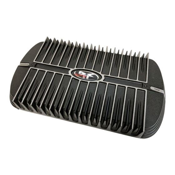
If, after reading your manual, you still have questions regarding this product, we recommend that you see your Rockford Fosgate dealer. If you need further assistance, you can call us direct at 1-800- 669-9899. Be sure to have your serial number, model number and date of purchase available when you call. - Page 3 Before installation, disconnect the battery negative (-) terminal to prevent damage to the unit, fire and/or possible injury. CONTENTS OF CARTON Either a Model 300X, 500X or 700X Punch 1 g/64” Allen Wrench 4Channel Amplifier 2 High Level Input Harness Installation &...
-
Page 4: Design Features
- The input gain control is preset to match the output of most source units. It can be adjusted to match output levels from a variety of source units. Internal Crossover (Models 300X & 500X) - Is a built-in 24dB/octave Butterworth filter... -
Page 5: Operation
DESIGN FEATURES Variable Crossover (Model 700X) - Is a built-in 24dB/octave Butterworth filter selectable for High-Pass (HP), All Pass (AP), or Low-Pass (LP) operation variable from 50Hz to 210Hz. High level Inputs - The high level inputs use a detachable connector terminated with 20 AWC... -
Page 6: Battery And Charging
THE SYSTEM If you do not feel comfortable with wiring your new unit, please see CAUTION: your local Authorized Rockford Fosgate Dealer for installation. Before installation, disconnect the battery negative (-) terminal ACAUTION: prevent damage to the unit, fire and/or possible injury. - Page 7 NOTE: Follow the diagrams for proper signal polarity. CAUTION: These amplifiers are not recommended for impedance loads below stereo and 452 bridged. Connect to Source unit’s Power Connection Models 300X al 500x *Keep Groundsas short as possible Vehicle Bsnerv...
- Page 8 Power Connection Model 700X chassis ground ofvehicle’ *Keep Grounds as short as possible 1 VehicleBattery 1 Z-Channel Wiring RCA OR High Level Inputs connect to Front Signal lmput Switch set to 2 Gain - front and rear set equally - front and rear set identically (example;...
- Page 9 INSTALLJTION Source Unit (L+)whii (G) wlllte/Bkk CChanmel ‘. . Amplifier S-Channel Wiring RCA OR High level Inputs connect to Front or Front and Rear Signal lmput Switch set to 2 or 4 NOTE: Reverse polarity on subwoofer front channel is set to HP (High Bridged Pass) and rear channel is set to LP (Low Pass)
-
Page 10: Using Passive Crossovers
USING PASSIVE CROSSOVERS A passive crossover is a circuit that uses capacitors and/or coils and is placed on speaker leads between the amplifier and speaker. The crossover delegates a specific range of frequencies to the speaker for optimum driver performance. A crossover network can perform one of three functions: High-Pass (capacitors),... -
Page 11: Crossover Frequency
NOTE: For a more in depth setting procedure, contact Rockford Technical Support. ADlUSTING CROSSOVER FREQUENCY Models 300X & 500X Placing the switch in the HP position sets the amplifier to the 120Hz High Pass mode, allowing only frequencies above the cut-off point to pass. -
Page 12: Accessories
OPERATION Model 700X Do the following individually for both front and rear if used. Placing the switch in the HP position sets the amplifier to the High Pass mode, enabling frequencies above the cut-off point to pass, adjustable between 50-21 OHz. Placing the switch in the AP position sets the amplifier to the All Pass mode, preventing crossover adjustment,... -
Page 13: Troubleshooting
TROUBLESHOOTING NOTE: If you are having problems after installation follow the Troubleshooting procedures below. Procedure 1: Check Amplifier for proper connections. Verify that POWER light is on. If POWER light is on skip to Step 2, if not continue. Check in-line fuse on battery positive cable. Replace if necessary. Verify that Ground connection is connected to clean metal of the vehicle’s chassis. -
Page 14: Specifications
Not Supplied Fuse Type Signal-to-Noise Ratio >l OOdB A-weighted Crossover Slope 24dB/octave Butterworth Crossover Frequency (Models 300X & 500X) Fixed 80Hz LP, AP, 120Hz Crossover Frequency (Model 700X) variable from 50Hz to 21 OHz Frequency Response 20Hz to 2OkHz k0.5dB... -
Page 15: Limited Warranty Information
This warranty covers only the original purchaser of Rockford product purchased from an Authorized Rockford Fosgate Dealer in the United States. In order to receive service, the purchaser must provide Rockford with a copy of the receipt stating the customer name, dealer name, product purchased and date of purchase. - Page 17 Printed in U.S.A. OS/Q2 B.M.


