Sony DSC-H7 Service Manual
Digital still camera
Hide thumbs
Also See for DSC-H7:
- Instruction manual (76 pages) ,
- Service manual (46 pages) ,
- Handbook (137 pages)
Table of Contents
Advertisement
Quick Links
SERVICE MANUAL
Ver 1.0 2007.04
Revision History
Revision History
How to use
How to use
Acrobat Reader
Acrobat Reader
Internal memory
Internal memory
ON BOARD
ON BOARD
Link
Link
SPECIFICATIONS
SERVICE NOTE
DISASSEMBLY
• Precaution on Replacing the SY-177 Board
The components identified by
mark 0 or dotted line with
mark 0 are critical for safety.
Replace only with part num-
ber specified.
DSC-H7/H9_L2
9-852-203-31
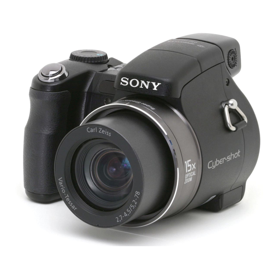
Photo: DSC-H7 Black Model
BLOCK DIAGRAMS
FRAME SCHEMATIC DIAGRAMS
SCHEMATIC DIAGRAMS
Les composants identifiés par une
marque 0 sont critiques pour la
sécurité.
Ne les remplacer que par une pièce
portant le numéro spécifié.
Sony EMCS Co.
DSC-H7/H9
PRINTED WIRING BOARDS
REPAIR PARTS LIST
DIGITAL STILL CAMERA
2
LEVEL
US Model
Canadian Model
AEP Model
UK Model
E Model
Australian Model
Hong Kong Model
Chinese Model
Korea Model
Argentine Model
Brazilian Model
Tourist Model
Japanese Model
2007D0200-1
© 2007.4
Published by Kohda TEC
Advertisement
Table of Contents

Related Manuals for Sony DSC-H7


Summary of Contents for Sony DSC-H7
- Page 1 Hong Kong Model Chinese Model Internal memory Internal memory Korea Model ON BOARD ON BOARD Argentine Model Brazilian Model Photo: DSC-H7 Black Model Tourist Model Japanese Model Link Link SPECIFICATIONS BLOCK DIAGRAMS PRINTED WIRING BOARDS SERVICE NOTE FRAME SCHEMATIC DIAGRAMS...
-
Page 2: Specifications
109.5 × 83.4 × 85.7 mm (4 3/8 × 3 3/8 × 3 3/8 inches) Aperture priority, Manual exposure, Scene Selection Dimensions: (9 modes) (W/H/D, excluding protrusions) (for both DSC-H9 and DSC-H7) White balance: Automatic, Daylight, Cloudy, Fluorescent 1,2,3, Mass: DSC-H9: Approx. - Page 3 CRITIQUES POUR LA SÉCURITÉ DE FONCTIONNEMENT. NE COMPONENTS WITH SONY PARTS WHOSE PART NUMBERS REMPLACER CES COMPOSANTS QUE PAR DES PIÈSES SONY APPEAR AS SHOWN IN THIS MANUAL OR IN SUPPLEMENTS DONT LES NUMÉROS SONT DONNÉS DANS CE MANUEL OU PUBLISHED BY SONY.
-
Page 4: Table Of Contents
PRINTED WIRING BOARDS AND SCHEMATIC DIAGRAMS 4-1. Frame Schematic Diagram ·············································· 4-1 4-2. Schematic Diagrams ························································ 4-2 4-3. Printed Wiring Boards ··················································· 4-22 REPAIR PARTS LIST 5-1. Exploded Views ······························································· 5-2 5-2. Electrical Parts List ························································· 5-7 DSC-H7/H9_L2 — 4 —... -
Page 5: Service Note
Block Detailed Code C : Corrected by customer Indicates the appropriate Refer to “1-2-3. Self-diagnosis Code Table”. E : Corrected by service step to be taken. engineer E.g. 13 ..Format the “Memory Stick Duo”. 32 ..Turn on power again. DSC-H7/H9_L2... -
Page 6: Process After Fixing Flash Error
2 Select [OK] with v, then press z. The settings are reset to the default setting. To cancel the resetting Select [Cancel] in step 2, then press z. • Make sure that the power is not disconnected during resetting. DSC-H7/H9_L2... -
Page 7: Method For Copying Or Erasing The Data In Internal
1 Select [Format] with v/V/b/B on the control button, then press z. The message “All data in internal memory will be erased” appears. 2 Select [OK] with v, then press z. The format is completed. To cancel the formatting Select [Cancel] in step 2, then press z. DSC-H7/H9_L2... -
Page 8: How To Write Data To Internal Memory
To change the setting, use the write enable tool “WriteEnableTool.exe”. Data writing method Connect the PC to the camera (USB mode: Mass Storage), and switch the driver to the “Sony Seus USB Driver”. Start the Write Enable Tool and the SeusEX. - Page 9 ENGLISH JAPANESE ENGLISH JAPANESE C : 3 2 : 00 “ ” DSC-H7/H9_L2...
- Page 10 ENGLISH JAPANESE ENGLISH JAPANESE 1-2-3. Ž © Œ È • f ’ f ƒ R • [ ƒ h • \ ÉuÉçÉbÉN è⁄ ç ◊ è«èÛ Å ^èÛ ë ‘ ã@î\ ÉRÅ[Éh eg ej e; es DSC-H7/H9_L2...
- Page 11 1-3. ƒ t ƒ ‰ ƒ b ƒ V ƒ … ƒ G ƒ ‰ • [ ” - • ¶ Ž ž ‚ Ì ‘ Î • ˆ – @ / / / 32MB ∗ ∗ ∗ ∗ ∗ DPOF “ ” / / / DSC-H7/H9_L2...
- Page 12 JAPANESE ENGLISH JAPANESE 1-5. “ à ‘ ƒ • ƒ ‚ ƒ Š ‚ Ö ƒ f • [ ƒ ^ ‚ ð • ‘ ‚ « – ß ‚ · • û – @ [Activate Write Enable Mode] DSC-H7/H9_L2...
-
Page 13: Note For Repair
To preparing the short jig, a small clip is attached to each end of a resistor of 1 k /1 W (1-215-869-11). Wrap insulating tape fully around the leads of the resistor to prevent electrical shock. R:1 k /1 W 1 k /1 W (Part code: 1-215-869-11) Wrap insulating tape. DSC-H7/H9_L2... - Page 14 2-1. DISASSEMBLY EXPLODED VIEW HARDWARE LIST EXPLODED VIEW HARDWARE LIST 2-1-1. CABINET(REAR) BLOCK ASSY AND JK-338 FLEXIBLE BOARD (DSC-H7) Note: High-voltage cautions Discharging the Capacitor Short-circuit between the two points with the short jig about 10 seconds. R:1 kΩ/1 W...
- Page 15 10 seconds. R:1 kΩ/1 W (Part code: 1-215-869-11) 1-5 (#12) 1-10 (#10) 1 Cabinet (Rear) Block ASSY 1-9 (#10) 1-14 1-13 1-12 1-6 (#10) 2-1(#10) 1-1 (#10) 2 JK-338 Flexible Board 1-11 1-8 (#10) 1-7 (#10) DSC-H7/H9_L2...
- Page 16 2-1-3. SY-177 BOARD, SY FRAME, CCD BLOCK ASSY AND LENS BLOCK ASSY 1-1 1-2 1-10 2-4 (Claw) 2 SY Frame (DSC-H9 only) 2-3 (#12) 2-2 (#12) 1 SY-177 Board 4 Lens Block Assy 1-7 (#12) 4-3(#74) 4-2(#74) 3-1(#73) 4-1(#74) 3 CCD Block Assy DSC-H7/H9_L2...
- Page 17 EXPLODED VIEW HARDWARE LIST EXPLODED VIEW HARDWARE LIST 2-1-4. LOUD SPEAKER BLOCK ASSY AND MODE DIAL BLOCK ASSY 2 Mode Dial Block Assy HELP 2-1(#75) 2-2(#75) 2-3(#75) 1 Loud Speaker Block Assy 1-3(#12) 1-1 (#12) DSC-H7/H9_L2...
- Page 18 EXPLODED VIEW HARDWARE LIST EXPLODED VIEW HARDWARE LIST 2-1-5. BATTERY BLOCK ASSY AND FLASH BLOCK ASSY 2 Flash Block Assy 2-3 (#12) HELP 1 Battery Block Assy 1-1 (#12) DSC-H7/H9_L2...
- Page 19 EXPLODED VIEW HARDWARE LIST EXPLODED VIEW HARDWARE LIST 2-1-6. LCD PANEL BLOCK (DSC-H7) 1-5 (#2) 1-3 (#10) 1-6 (#2) 1 LCD Panel Block DSC-H7/H9_L2...
- Page 20 EXPLODED VIEW HARDWARE LIST EXPLODED VIEW HARDWARE LIST 2-1-7. LCD PANEL BLOCK (DSC-H9) 1-2 (#12) 1 LCD Panel Block Assy 1-4 (#14) 1-6 (#12) DSC-H7/H9_L2...
- Page 21 EXPLODED VIEW HARDWARE LIST EXPLODED VIEW HARDWARE LIST 2-1-8. PANEL BLOCK ASSY AND LCD BLOCK ASSY (DSC-H9) 1-2 (#14) HELP 1-9 (#14) 1-10 (Claw) 1 Panel Block Assy 1-4 (#10) 1-8 (#14) 1-5 (#10) 1-12 1-11 (Claw) 1-7 (#14) 2 LCD Block Assy 2-2 (#14) DSC-H7_H9_L2 2-9E...
- Page 22 When installing theree harness, do not intersect the harness in the part between “a” and “b” as shown in figure. Arrange the strobe harness in this range. Strobe harness Strobe harness Arrange the strobe harness inside of the rib DSC-H7/H9_L2 HELP...
- Page 23 CK-182 board 25mm Note : • Ú ’ … Ž † (2-649-300-01) ‚ ð • Ø ‚ Á ‚ Ä Ž g — p • B Note : Cut SHEET, ADHESIVE (2-649-300-01) into the desired length and use it. DSC-H7/H9_L2 HELP...
- Page 24 On assembling, set the NS lever and the NIGHTSHOT switch up and adjust the notch of NS upper arm to the projection on NS lever. Upper arm, NS NS lever NIGHT SHOT Cabinet (Rear) Block Assy switch When assembling the mode dial, match the direction of the cutting lack as shown in figure Cutting lack DSC-H7/H9_L2 HELP...
- Page 25 3. BLOCK DIAGRAMS Link Link OVERALL BLOCK DIAGRAM (1/2) POWER BLOCK DIAGRAM (1/2) POWER BLOCK DIAGRAM (2/2) OVERALL BLOCK DIAGRAM (2/2) DSCH7/H9_L2...
-
Page 26: Memory
V5A, V5B, V6 - V10 BL_H, BL_L IC211 IC_211_3_SO (1/2) CN001 CN002 XIC_211_3_SCK BL_H OVERALL BL_L CAMERA (2/2) SUB_CONT Q301 DSP/ SYSTEM CONTROL CSUB DSC-H7 XDD_SYS_RST (3/7) CK-181 FLEXIBLE CK-180 BOARD (4/7) (5/7) BOARD CN001 Q302 VSUB_CONT_PRE VSUB_CONT_POST IC_211_2_SO IC401 AF25 CN401 XIC_211_2_SCK IRIS... -
Page 27: Overall Block Diagram (1/2)
BUFFER IC_211_PROUT HD_PR VOUT_2 CN001 AC12 FINDER/LCD DIRECT_PB MULTI CONNECTOR CN103 CN101 XHD_EN S001 XAV_JACK_IN XAV_JACK_IN LF001 DSC-H7 USB_DP/DM USB_DP/DM DSC-H9 SW-500 BOARD IC_211_1_UO, IC_211_1_UI UART_TX, UART_RX PL-047 BOARD CN102 RY201 CN201 CN101 IC_211_2_SO (PLUNGER) IC_211_2_SCK IC211 OVERALL S101 - S104... -
Page 28: Power Block Diagram (1/2)
XPWR_ON DIRECT_PB XPOWER_ON0 LXSU L007 DIRECT_PB DDC5PSW_EN IC_211_0_SO XPOWER_ON2 FBSU IC_211_0_SO IC_211_0_SI FR_SI L003 D006 XIC_211_SCK IC_211_0_SI FR_SO SWLED XCS_FR XIC_211_SCK FR_SCK LXLED XCS_FR XCS_EX FBHLED XACV_IN FBLLED BATT_SIG Q006 PVLED DD-273 FLEXIBLE BL_EN1 BL_EN2 ONLED 36 BOARD (2/2) DSC-H7/H9_L2... -
Page 29: Power Block Diagram (2/2)
3-3. POWER BLOCK DIAGRAM (2/2) ( ) : Number in parenthesis ( ) indicates the division number of schematic diagram where the component is located. DSC-H9 DSC-H7 SY-177 BOARD (2/2) CK-182 FLEXIBLE CK-179 BOARD CK-181 FLEXIBLE CK-180 BOARD CN001 CN001... -
Page 30: Printed Wiring Boards And Schematic Diagrams
4. PRINTED WIRING BOARDS AND SCHEMATIC DIAGRAMS 4-1. FRAME SCHEMATIC DIAGRAM DSC-H7 DSC-H9 DD-273 FLEXIBLE BOARD MS-364 BOARD ( SIDE A ) MS-366 BOARD ( SIDE A ) LEVEL3 DD-272 BOARD (SIDE A) CN302 CN302 LOCK MEMORY STICK DUO LOCK... -
Page 31: Schematic Diagrams
SW-499 BOARD:DSC-H9 CD-703 FLEXIBLE BOARD (CCD IMAGER) (SWITCH) CK-180 BOARD:DSC-H7 SW-500 BOARD:DSC-H7 (SY TO LCD RELAY) (SWITCH) CK-181 FLEXIBLE BOARD:DSC-H7 SW-504 FLEXIBLE BOARD (SY TO SW RELAY) (SY TO CK RELAY) CK-179 BOARD:DSC-H9 PL-046 BOARD:DSC-H7 (SY TO LCD RELAY) (PLUNGER) - Page 32 In addition, ensure that the receiver is not covered with Les composants identifiés par une marque 0 sont dusts nor exposed to strong light. critiques pour la sécurité. Ne les remplacer que par une pièce portant le numéro spécifie. DSC-H7/H9_L2...
-
Page 33: Cd-703 Flexible Board
LEVEL3 LND026 REG_GND LND027 REG_GND LND028 REG_GND LND029 REG_GND LND030 LND031 REG_GND LND032 LND033 REG_GND LND034 LND035 REG_GND LND036 C006 LND037 REG_GND 0.1u LND038 LND039 REG_GND LND040 CAM_12V LND041 REG_GND LND042 REG_GND LND043 REG_GND LND044 CCD_OUT LND045 REG_GND DSC-H7/H9_L2 CD-703... - Page 34 Schematic diagrams of the SY-177 board is not shown. Pages from 4-4 to 4-10 are not shown. DSC-H7/H9_L2...
- Page 35 DSC-H7 CK-180 BOARD XX MARK:NO MOUNT SY TO LCD RELAY LCD9001 BACK LIGHT CK-181 VCOM FLEXIBLE BOARD VDDREG RESET Z SY TO CK RELAY SPENA C014 SPDA SPCK LND033 LND032 C016 R004 2.2u VDDD BL_H BL_H LND028 BL_H C008 C005...
- Page 36 C001 OUT18V XDD_SYS_RST LND004 REG_GND XDD_SYS_RST VCCI D_1.8V PANEL_6.4V VCC2(6.4V) P_6.4V LND002 REG_GND L002 10uH VCC(3V) D_3V LND001 D_3.0V PANEL_6.4V L001 CN002 REG_GND 10uH C011 C012 C015 C013 D_3.0V CN001 LND030 LND029 GND2 GND2 STATIC_GND LND001 DSC-H7/H9_L2 CK-179, CK-182 4-12...
- Page 37 USB_GND LF001 LND008 USB_DM LND007 USB_DP USB_DP UART_Tx LND006 USB_GND USB_GND XPOWER_ON LND005 USB_VBUS USB_VBUS ACV_GND LND004 IC_211_PBOUT HD_Pb ACV_GND LND003 REG_GND HD_Pr ACV_GND LND002 IC_211_PROUT LND001 REG_GND CN001 28P (MULTI CONNECTOR) TO AV/USB MULTICABLE OR CRADLE DSC-H7/H9_L2 JK-338 4-13...
-
Page 38: Ms-365 Flexible Board
Q301 LND316 SCLK SCLK LND332 SCLK SSM6E01TU SWITCH FB305 LND317 REG_GND REG_GND LND333 REG_GND C304 0.001u R303 D302 CN301 2200 MA2SD32008S0 C303 0.1u R302 R305 R304 C301 3300 470k 6.3V C302 0.1u LND301 SOL001 STATIC_GND DSC-H7/H9_L2 MS-364, MS-365, MS-366 4-14... - Page 39 PY-002 SW-500 BOARD ( DSC-H7 ) FLEXIBLE BOARD SW-499 BOARD ( DSC-H9 ) SWITCH SWITCH REG_GND LND118 REG_GND XX MARK:NO MOUNT REG_GND LND119 REG_GND S001 REG_GND LND120 REG_GND S002 FINDER/LCD LND121 LND122 DIRECT_PB DIRECT_PB SW-504 LCD_SW LND123 LCD_SW CN103 FLEXIBLE BOARD...
- Page 40 • Refer to page 4-2 for mark 0. PL-046 BOARD (DSC-H7) FLEXIBLE FLAT CABLE(PL-002) PL-047 BOARD (DSC-H9) PLUNGER XX MARK:NO MOUNT CN201 D201 MA2S111-(K8).SO LND001 REG_GND REG_GND LND007 REG_GND RY201 PLUNGER LND002 REG_GND REG_GND REG_GND SY-177 LND008 D202 C201 LND003...
- Page 41 REG_GND R017 DSC-H9 (SHUTTER) 2200 R018 LND003 MODE_DIAL2 3300 LND002 XPWR_LED S003 LND001 D_3.0V R014 8200 R019 R001 4700 R020 2200 2.2k R021 2200 R022 3300 S004 D003 /BRK SML-412MWT86 (POWER) R023 4700 R015 8200 LND021 Static_GND DSC-H7/H9_L2 PW-134 4-17...
- Page 42 Schematic diagrams of the DD-272 board is not shown. Pages from 4-18 to 4-20 are not shown. DSC-H7/H9_L2...
-
Page 43: Dd-273 Flexible Board
LND128 LND064 A_3.0V A_3.0V LND129 LND065 ACV_UNREG2 ACV_UNREG2 LND130 LND066 ACV_UNREG2 ACV_UNREG2 LND131 LND067 ACV_UNREG2 ACV_UNREG2 LND132 LND003 LND068 ACV_UNREG2 ACV_UNREG2 LND133 REG_GND LND069 MS_VCC MS_VCC LND134 LND070 MS_VCC MS_VCC LND135 LND071 PANEL_6.4V PANEL_6.4V LND136 DSC-H7/H9_L2 DC-107, DD-273, ST-166 4-21... -
Page 44: Printed Wiring Boards
4-3. PRINTED WIRING BOARDS Link Link CD-703 FLEXIBLE BOARD PY-002 FLEXIBLE BOARD CK-180 BOARD: DSC-H7 SW-499 BOARD: DSC-H9 CK-181 FLEXIBLE BOARD: DSC-H7 SW-500 BOARD: DSC-H7 CK-179 BOARD: DSC-H9 PL-046 BOARD: DSC-H7 CK-182 FLEXIBLE BOARD: DSC-H9 PL-047 BOARD: DSC-H9 JK-338 BOARD... - Page 45 : pattern of the rear side (The other layers’ patterns are not indicated) • Through hole is omitted. • There are a few cases that the part printed on diagram isn’t mounted in this model. • C: panel designation DSC-H7/H9_L2 4-22...
- Page 46 Printed wiring boards of the SY-177 and DD-272 boards are not shown. Pages from 4-23 to 4-24 are not shown. DSC-H7/H9_L2...
-
Page 47: Ck-181 Flexible Board
CD-703 (2 layers), CK-180 (2 layers), Ck-181 (1 layer) : Uses unleaded solder. CD-703 FLEXIBLE BOARD DSC-H7 (Note) CK-181 FLEXIBLE BOARD C010 R009 C001 LND001 LND002 LND003 LND004 LND005 LND006 LND028 LND007 LND027 LND008 LND009 LND026 LND010 LND011 LND025 LND029... -
Page 48: Ck-182 Flexible Board
CK-182 FLEXIBLE BOARD LND028 LND027 LND026 LND025 LND024 LND023 LND032 LND031 LND022 LND021 LND020 LND019 LND018 LND017 LND016 LND015 LND014 LND013 LND012 LND011 LND029 LND030 LND010 LND009 LND008 LND007 LND006 LND005 LND004 < > 1-871-940- LND002 LND001 DSC-H7/H9_L2 CK-179, CK-182 4-26... -
Page 49: Ms-364 Board ( Side A)
JK-338 (2 layers), MS-364 (2 layers), MS-366 (2 layers) : Uses unleaded solder. DSC-H7 MS-364 BOARD ( SIDE A ) MS-364 BOARD ( SIDE B ) CN301 LND301 SOL001 R307 R313 JK-338 FLEXIBLE BOARD R308 R314 CN302 MEMORY R309 R315... -
Page 50: Py-002 Flexible Board
1-871-937- LND121 LND120 LND119 LND118 Note: S001 and S002 are not supplied, but they are included in the PY-002 flexible board. DSC-H9 DSC-H7 SW-499 BOARD ( SIDE A ) SW-500 BOARD ( SIDE A ) S101 R104 R103 S101 (ZOOM) - Page 51 PL-046 (2 layers), PL-047 (2 layers), PW-134 (2 layers), DC-107 (1 layer), ST-166 (1 layer) : Uses unleaded solder. PW-134 FLEXIBLE BOARD DSC-H7 PL-046 BOARD PL-046 BOARD C001 ( SIDE A ) ( SIDE B ) IC001 LND001 LND002 LND003...
- Page 52 Mounted parts location of the SY-177 and DD-272 boards are not shown. Page 4-30 to 4-31 is not shown. DSC-H7/H9_L2 4-31...
-
Page 53: Repair Parts List
EXPLODED VIEWS EXPLODED VIEWS Link Link OVERALL SECTION:DSC-H7 OVERALL SECTION:DSC-H9 CABINET (FRONT) SECTION-1 CABINET (FRONT) SECTION-2 CABINET (FRONT) SECTION-3 CABINET (REAR) SECTION:DSC-H7 CABINET (REAR) SECTION:DSC-H9 LCD SECTION:DSC-H9 ELECTRICAL PARTS LIST ELECTRICAL PARTS LIST Link Link ACCESSORIES ACCESSORIES CD-703 FLEXIBLE BOARD... - Page 54 , µPB... , µPC... , µPC... , uPD..., µPD... • Abbreviation : Argentine model AUS : Australian model : Brazilian model : Chinese model CND : Canadian model HK : Hong Kong model : Japanese model : Tourist model : Korea model DSC-H7/H9_L2...
-
Page 55: Exploded Views
5. REPAIR PARTS LIST 5. REPAIR PARTS LIST DISASSEMBLY HARDWARE LIST DISASSEMBLY HARDWARE LIST 5-1. EXPLODED VIEWS 5-1-1. OVERALL SECTION : DSC-H7 Cabinet (Front) Section-1 (See page 5-4.) Cabinet (Rear) Section (See page 5-7.) Ref. No. Part No. Description Ref. No. - Page 56 3-106-782-11 LID, SY BLIND (BLACK) 3-106-776-11 LID, JACK (BLACK) * 52 3-106-777-01 HOLDER, MULTI (SILVER) 2-599-475-31 SCREW (M1.7) (Silver) * 52 3-106-777-11 HOLDER, MULTI (BLACK) 3-080-204-21 SCREW, TAPPING, P2 (Black) A-1251-450-A JK-338 BOARD, COMPLETE * 54 3-106-778-01 PLATE, MULTI FIXED DSC-H7/H9_L2...
- Page 57 3-211-271-01 SHEET, SY RADIATION, (H9) * 103 3-106-773-01 PLATE, SY GROUND 3-080-204-21 SCREW, TAPPING, P2 (Black) * 104 3-106-772-01 FRAME, SY 3-086-156-61 SCREW B1.2 (Black) 2-666-551-31 SCREW, TAPPING, P2 (Silver) * 105 3-106-681-01 RETAINER, MODULE A-1251-208-A CCD BLOCK ASSY X-2177-453-1 VF ASSY DSC-H7/H9_L2...
- Page 58 1-817-331-11 DC JACK 5P (DC IN) 1-965-160-11 HARNESS (HN-044) (BLUE) 0 RY201 1-455-038-11 SOLENOID, PLUNGER 3-106-774-01 CABINET (UPPER) (SILVER) (H7) 3-106-774-11 CABINET (UPPER) (SILVER) (H9) 3-080-204-21 SCREW, TAPPING, P2 (Black) 3-106-774-21 CABINET (UPPER) (BLACK) (H9) 2-666-551-01 SCREW, TAPPING, P2 (Silver) DSC-H7/H9_L2...
- Page 59 1-825-262-71 LOUD SPEAKER (1.6CM) X-2177-465-1 CABINET (FRONT) ASSY (450) (SILVER) (H9) 2-599-475-31 SCREW (M1.7) (Silver) X-2177-466-1 CABINET (FRONT) ASSY (450B) (BLACK) (H9) 3-080-204-21 SCREW, TAPPING, P2 (Black) 3-106-768-01 RING, LENS (SILVER) 2-666-551-01 SCREW, TAPPING, P2 (Silver) 3-106-768-11 RING, LENS (BLACK) DSC-H7/H9_L2...
- Page 60 5. REPAIR PARTS LIST 5. REPAIR PARTS LIST DISASSEMBLY HARDWARE LIST DISASSEMBLY HARDWARE LIST 5-1-6. CABINET (REAR) SECTION : DSC-H7 ns: not supplied LCD902 Ref. No. Part No. Description Ref. No. Part No. Description 3-106-736-01 CUSHION (350), LCD (H7) 1-480-173-21 SWITCH BLOCK, CONTROL (SW60350) (BLACK)
- Page 61 X-2178-452-1 BLIND ASSY, CABINET (REAR) (SILVER) (H9) 1-872-388-11 SW-504 FLEXIBLE BOARD A-1251-456-A SW-499 BOARD, COMPLETE (H9) 2-599-475-31 SCREW (M1.7) (Silver) 3-106-738-01 SHEET, MUFFLE 3-080-204-21 SCREW, TAPPING, P2 (Black) 2-599-475-11 SCREW (M1.7) (Silver) 1-480-173-11 SWITCH BLOCK, CONTROL (SW60350) 2-666-551-01 SCREW, TAPPING, P2 (Silver) (SILVER) (H9) DSC-H7/H9_L2...
- Page 62 1-480-023-11 BLOCK, LIGHT GUIDE PLATE (3.0) (H9) LCD901 A-1257-852-A SERVICE, LCD BLOCK ASSY (H9) 3-106-603-11 BLIND, HINGE (BLACK) (H9) X-2177-441-1 CABINET (C) ASSY (B), P (BLACK) (H9) 2-599-475-31 SCREW (M1.7) (Silver) 3-106-602-11 COVER (M), HINGE (BLACK) (H9) 2-599-475-11 SCREW (M1.7) (Silver) DSC-H7/H9_L2...
-
Page 63: Electrical Parts List
1-218-946-11 RES-CHIP 1/16W Pages 5-11 to 5-12 is not shown. R005 1-218-946-11 RES-CHIP 1/16W Note: Be sure to read “Precautions for Replacement of • Refer to page 5-1 for mark 0. Imager” on page 4-2 when changing the imager. DSC-H7/H9_L2 5-10... - Page 64 < CAPACITOR > R315 1-469-580-11 FERRITE C201 1-165-908-11 CERAMIC 10% 10V R316 1-469-580-11 FERRITE R317 1-469-580-11 FERRITE < CONNECTOR > R318 1-218-939-11 RES-CHIP 1/16W * CN201 1-817-554-51 CONNECTOR, FFC/FPC 6P • Refer to page 5-1 for mark 0. DSC-H7/H9_L2 5-13...
- Page 65 2.2K 1/16W R104 1-218-959-11 RES-CHIP 3.3K 1/16W R018 1-216-827-11 METAL CHIP 3.3K 1/10W R105 1-218-961-11 RES-CHIP 4.7K 1/16W R019 1-216-829-11 METAL CHIP 4.7K 1/10W R020 1-216-825-11 METAL CHIP 2.2K 1/10W • Refer to page 5-1 for mark 0. DSC-H7/H9_L2 5-14...
- Page 66 1-786-819-22 TACTILE SWITCH (ZOOM T) S102 1-786-819-22 TACTILE SWITCH (ZOOM W) S103 1-786-157-11 TACTILE SWITCH (MENU) S104 1-786-157-11 TACTILE SWITCH (HOME) 1-872-388-11 SW-504 FLEXIBLE BOARD ********************* Electrical parts list of SY-177 board are not shown. Pages 5-16 to 5-19 is not shown. DSC-H7/H9_L2 5-15...
-
Page 67: Checking Supplied Accessories
"Cyber-shot Handbook"/ 3-196-622-11 (FINNISH) 0 1-569-008-12(E) "Cyber-shot Step-up Guide) 3-196-622-21 (NORWEGIAN) 3-196-618-01 (EXCEPT US, J) 3-196-622-31 (DANISH) 3-196-619-01 (US) 3-196-622-41 (THAI) 3-209-351-01 (J) 3-196-622-51 (MALAY) 3-196-622-61 (TURKISH) 3-196-622-71 (GREEK) 0 1-569-007-12(JE) • Refer to the cover for mark 0. DSC-H7/H9_L2 5-20E... - Page 68 HARDWARE LIST (1/4) #1: M1.7 X 2.5 #2: M1.7 X 4.0 #3: M1.7 X 2.5 #4: M1.4 X 2.5 (Tapping) (Black) (Black) (Red) (Dark Silver) 2-635-562-11 2-635-562-31 2-660-401-01 3-348-998-81 #5: M1.7 X 3.5 (Tapping) #6: M1.4 X 1.7 #7: M1.7 X 1.6 #8: M1.7 X 3.5 (Tapping) (Black) (Silver)
- Page 69 HARDWARE LIST (2/4) #21: M1.4 X 3.0 #22: M1.7 X 5.0 (Tapping) #23: M1.7 X 4.0 (Tapping) #24: B1.7 X 5.5 (Tapping) (Black) (Silver) (Black) (Black) 2-662-396-21 3-083-261-01 3-080-204-11 4-679-805-11 #25: M1.7 X 3.0 #26: M1.4 X 2.0 #27: M1.4 X 2.0 #28: M1.4 X 4.0 (Tapping) (Black) (Silver)
- Page 70 HARDWARE LIST (3/4) #41: M3.0 X 8.0 (Tapping) #42: M2.0 X 4.0 (Tapping) #43: M1.7 X 4.0 #44: M1.7 X 3.0 (Tapping) (Silver) (Silver) (Red) (Silver) 3-065-748-01 7-628-253-00 2-660-401-31 3-078-890-61 #45: M1.4 X 2.5 #46: M1.7 X 3.0 #47: M1.4 X 3.0 (Tapping) #48: M1.7 X 2.5 (Silver) (Red)
- Page 71 HARDWARE LIST (4/4) #64: M1.7 X 5.0 (Tapping) #61: M3.0 X 10.0 #62: M2.0 X 3.0 #63: M5.0 X 12.5 (Silver) (Black) (Silver) (Black) 2-666-551-21 7-682-549-09 3-080-202-21 3-060-811-21 12.5 10.0 #65: M1.4 X 3.5 #66: M1.4 X 1.4 #67: M1.4 X 2.0 #68: M1.7 X 4.0 (Silver) (Silver)
- Page 72 [Description of main button functions on toolbar of the Adobe Acrobat Reader Ver5.0 (for Windows)] Toolbar Printing a text Reversing the screens displayed once • To reverse the previous screens (operation) one by one, click 1. Click the Print button 2.
-
Page 73: Revision History
Reverse 985220331.pdf Revision History S.M. Rev. Ver. Date History Contents issued 2007.04 Official Release — — DSC-H7/H9_L2...