Hitachi SJ100 Instruction Manual
Sj100 series
Hide thumbs
Also See for SJ100:
- Instruction manual (160 pages) ,
- Service manual (75 pages) ,
- Quick reference manual (25 pages)
Table of Contents
Advertisement
Quick Links
Advertisement
Chapters
Table of Contents
Troubleshooting

Related Manuals for Hitachi SJ100


Summary of Contents for Hitachi SJ100
- Page 1 SJ100 Series Inverter Instruction Manual • Single-phase Input 200V Class • Three-phase Input 200V Class • Three-phase Input 400V Class Manual Number: NB585XF December 2003 After reading this manual, keep it handy for future reference. Hitachi Industrial Equipment Systems Co., Ltd.
-
Page 2: Hazardous High Voltage
Safety Messages For the best results with the SJ100 Series inverter, carefully read this manual and all of the warning labels attached to the inverter before installing and operating it, and follow the instructions exactly. Keep this manual handy for quick reference. -
Page 3: General Precautions - Read These First
Equipment Systems Co., Ltd. CAUTION: Be sure to connect a motor thermal disconnect switch or overload device to the SJ100 series controller to assure that the inverter will shut down in the event of an overload or an overheated motor. - Page 4 Cable support Cable CAUTION: A double-pole disconnection device must be fitted to the incoming main power supply close to the inverter. Additionally, a protection device meeting IEC947-1/ IEC947-3 must be fitted at this point (protection device data shown in “Determining Wire and Fuse Sizes”...
-
Page 5: Index To Warnings And Cautions In This Manual
Index to Warnings and Cautions in This Manual Installation - Cautions for Mounting Procedures CAUTION: The inverter is shipped with a plastic cover over the top vent grill. REMOVE this cover after the installation is complete. Operation with this cover in place will not allow proper cooling, and damage to the inverter may result. - Page 6 Otherwise, there is the possibility of damage to the inverter and the danger of fire. CAUTION: Be sure not to connect an AC power supply to the output terminals. Otherwise, there is the possibility of damage to the inverter and the danger of injury and/or fire.
- Page 7 CAUTION: Remarks for using ground fault interrupter breakers in the main power supply: Adjustable frequency inverters with CE-filters (RFI- filter) and shielded (screened) motor cables have a higher leakage current toward Earth GND. Especially at the moment of switching ON this can cause an inadvertent trip of ground fault interrupters.
- Page 8 (be sure to design the machine so that safety for personnel is secure even if it restarts.) Otherwise, it may cause injury to personnel. WARNING: If the power supply is cut OFF for a short period of time, the inverter may restart operation after the power supply recovers if the Run command is active.
- Page 9 viii WARNING: Be sure not to touch the inside of the energized inverter or to put any conductive object into it. Otherwise, there is a danger of electric shock and/or fire. WARNING: If power is turned ON when the Run command is already active, the motor will automatically start and injury may result.
-
Page 10: General Warnings And Cautions
Warnings and Cautions for Troubleshooting and Maintenance WARNING: Wait at least five (5) minutes after turning OFF the input power supply before performing maintenance or an inspection. Other- wise, there is the danger of electric shock. WARNING: Make sure that only qualified personnel will perform maintenance, inspection, and part replacement. - Page 11 (Mgo) on the power supply side, so that the circuit does not allow automatic restarting after the power supply recovers. If the optional remote operator is used and the retry function has been selected, this will also cause automatic restarting when a Run command is active.
- Page 12 MUST install an input-side AC reactor of 3% (at a voltage drop at rated current) with respect to the supply voltage on the power supply side. Also, where the effects of an indirect lightning strike are possible, install a lightning conductor.
-
Page 13: Ul® Cautions, Warnings, And Instructions
CAUTION: When the EEPROM error E08 occurs, be sure to confirm the setting values again. CAUTION: When using normally closed active state settings (C_11 to C_16) for exter- nally commanded Forward or Reverse terminals [FW] or [RV], the inverter may start automatically when the external system is powered OFF or disconnected from the inverter! So, do not use normally closed active state settings for Forward or Reverse terminals [FW] or [RV] unless your system design protects against unintended motor... - Page 14 The connector must be fixed using the crimping tool specified by the connector manufacturer. Wiring Size Inverter Model Range (AWG) Terminal (ring lug) xiii SJ100 Inverter Torque ft-lbs (N-m) Cable support Cable...
-
Page 15: Motor Overload Protection
200V 0.75 400V Motor Overload Protection Hitachi SJ100 inverters provide solid state motor overload protection, which depends on the proper setting of the following parameters: • B_12 “electronic overload protection” • B212 “electronic overload protection, 2nd motor” Set the rated current [Amperes] of the motor(s) with the above parameters. The setting range is 0.5 * rated current to 1.2 * rated current. -
Page 16: Table Of Contents
UL® Cautions, Warnings, and Instructions Table of Contents Revisions Contact Information Chapter 1: Getting Started Introduction SJ100 Inverter Specifications Introduction to Variable-Frequency Drives Frequently Asked Questions Chapter 2: Inverter Mounting and Installation Orientation to Inverter Features Basic System Description Step-by-Step Basic Installation... - Page 17 Warranty Appendix A: Glossary and Bibliography Glossary Bibliography Appendix B: Drive Parameter Settings Tables Introduction Parameter Settings for Keypad Entry Appendix C: CE–EMC Installation Guidelines CE–EMC Installation Guidelines Hitachi EMC Recommendations Index 4–2 4–4 4–5 4–8 4–24 4–32 4–33 4–35 4–39...
-
Page 18: Revisions
Revision D Minor corrections throughout Revision E Minor corrections throughout Revision F Minor corrections throughout Revision History Table Date of Issue August 1999 xvii SJ100 Inverter Operation Manual No. April 1999 NB585X May 1999 NB585XA NB585XB May 2002 NB585XC Nov. 2002... -
Page 19: Contact Information
NOTE: To receive technical support for the Hitachi inverter you purchased, contact the Hitachi inverter dealer from whom you purchased the unit, or the sales office or factory contact listed above. Please be prepared to provide the following inverter nameplate information: 1. - Page 20 Getting Started In This Chapter... — Introduction — SJ100 Inverter — Introduction to Variable-Frequency Drives — Frequently Asked Questions Specifications... page...
-
Page 21: Introduction
• Motor constants are programmable, or may be set via auto-tuning • PID control adjusts motor speed automatically to maintain a process variable value The design in Hitachi inverters overcomes many of the traditional trade-offs between speed, torque and efficiency. The performance characteristics are: •... - Page 22 1–3 SJ100 Inverter A full line of accessories from Hitachi is available to complete your motor application. These include: • Digital remote operator keypad • Braking resistors (shown at right) • Radio noise filters • CE compliance filters • DIN rail mounting adapter (35mm rail size)
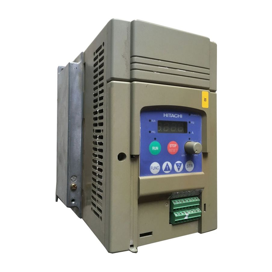
- Page 23 Introduction Inverter Specifications Label The Hitachi SJ100 inverters have product labels located on the right side of the housing, as pictured below. Be sure to verify that the specifications on the labels match your power source, motor, and application safety requirements.
-
Page 24: Sj100 Inverter Specifications
SJ100 Inverter Specifications Model-specific tables for 200V and 400V class inverters The following tables are specific to SJ100 inverters for the 200V and 400V class model groups. Note that “General Specifications” on page 1–9 groups. Footnotes for all specifications tables follow the table below. - Page 25 Note 5: When SLV is selected, please set the carrier frequency higher than 2.1 kHz. Note 6: At the rated voltage when using a Hitachi standard 3-phase, 4-pole motor (when selecting sensorless vector control—SLV). Note 7: The braking torque via capacitive feedback is the average deceleration torque at the shortest deceleration (stopping from 50/60 Hz as indicated).
- Page 26 SJ100 Inverter Specifications, continued... Item SJ100 inverters, CE version 200V models UL version Applicable motor size *2 Rated capacity 230V (kVA) *12 240V Rated input voltage Rated input 1-phase current (A) 3-phase Rated output voltage *3 Rated output current (A)
- Page 27 1–8 SJ100 Inverter Specifications Item SJ100 inverters, CE version 400V models UL version Applicable motor size *2 Rated capacity (460V) kVA Rated input voltage Rated input current (A) Rated output voltage *3 Rated output current (A) Efficiency at 100% rated output (%)
-
Page 28: General Specifications
50/60 Hz torque, short time with resistor stop *7 DC braking Weight General Specifications The following table applies to all SJ100 inverters. Item Protective housing *1 Control method Output frequency range *4 Frequency accuracy Frequency setting resolution Volt./Freq. characteristic *5... - Page 29 1–10 SJ100 Inverter Specifications Item Input Freq. Operator panel Up and Down keys / Value settings signal setting Potentiometer External signal FWD/ Operator panel Run/Stop (Forward/Reverse run change by command) External signal Forward run/stop, Reverse run/stop Intelligent input terminal Output...
- Page 30 10VDC nominal, 10 mA maximum Alarm relay contacts 250 VAC, 2.5A (R load) max., 0.2A (I load, P.F.=0.4) max. 100 VAC, 10mA min. 30 VDC, 3.0A (R load) max., 0.7A (I load, P.F.=0.4) max. 5 VDC, 100mA min. SJ100 Inverter 4–6. Ratings 1–11...
-
Page 31: Derating Curves
Use the following derating curves to help determine the optimal carrier frequency setting for your inverter, and to find the output current derating. Be sure to use the proper curve for your particular SJ100 inverter model number. Legend: SJ100–002NFE/NFU... - Page 32 Derating curves, continued... SJ100–007NFE/NFU 100% % of rated output current SJ100–0015NFE/NFU 100% % of rated output current SJ100–022NFE/NFU 100% % of rated output current SJ100 Inverter Carrier frequency Carrier frequency Carrier frequency 1–13...
- Page 33 1–14 SJ100 Inverter Specifications Derating curves, continued... SJ100–037LF/LFU % of rated output current SJ100–055LFU % of rated output current SJ100–075LFU % of rated output current 100% Carrier frequency 100% Carrier frequency 100% Carrier frequency...
- Page 34 Derating curves, continued... SJ100–004HFE/HFU 100% % of rated output current SJ100–007HFE/HFU 100% % of rated output current SJ100–015HFE/HFU 100% % of rated output current SJ100 Inverter Carrier frequency Carrier frequency Carrier frequency 1–15...
- Page 35 1–16 SJ100 Inverter Specifications Derating curves, continued... SJ100–022HFE/HFU % of rated output current SJ100–040HFE/HFU % of rated output current SJ100–055HFE/HFU % of rated output current 100% Carrier frequency 100% Carrier frequency 100% Carrier frequency...
- Page 36 1–17 SJ100 Inverter Derating curves, continued... SJ100–075HFE/HFU 100% % of rated output current Carrier frequency...
-
Page 37: Introduction To Variable-Frequency Drives
Introduction to Variable-Frequency Drives The Purpose of Motor Speed Control for Industry Hitachi inverters provide speed control for 3-phase AC induction motors. You connect AC power to the inverter, and connect the inverter to the motor. Many applications benefit from a motor with variable speed, in several ways: •... - Page 38 From this it mathematically calculates two vector currents. One vector is related to motor flux current, and the other to motor torque current. The ability to separately control these two vectors is what allows the SJ100 to deliver extraordinary low-speed performance and speed control accuracy.
- Page 39 The Hitachi inverter is a rugged and reliable device. The intention is for the inverter to assume the role of controlling power to the motor during all normal operations. There- fore, this manual instructs you not to switch off power to the inverter while the motor is running (unless it is an emergency stop).
- Page 40 (see page 5–2 “Dynamic Braking” on page 5–5 continuously overhaul the motor for extended periods of time, the SJ100 may not be suitable (contact your Hitachi distributor). The inverter parameters include acceleration and deceleration, which you can set to match the needs of the application.
- Page 41 FWD and REV commands determine the direction before the motion starts. NOTE: The SJ100 can move loads in both directions. However, it is not designed for use in servo-type applications that use a bipolar velocity signal that determines direction. Set speed...
-
Page 42: Frequently Asked Questions
Amplifier is a term almost exclusively used to describe drives for servo or stepper motors. Although the SJ100 inverter is a variable speed drive, can I use it in a fixed-speed application? Yes, sometimes an inverter can be used simply as a “soft-start”... - Page 43 The greater the number of poles, the slower the top motor speed will be, but it will have higher torque at the base speed. Will I be able to add dynamic (resistive) braking to my Hitachi SJ100 drive after the initial installation? Yes.
- Page 44 Other applications may not need noise suppression, unless you notice electrical interference with the operation of other devices. The SJ100 features a PID loop feature. PID loops are usually associated with chemical processes, heating, or process industries in general. How could the PID...
- Page 45 Inverter Mounting and Installation In This Chapter... — Orientation to Inverter Features — Basic System Description — Step-by-Step Basic — Powerup Test — Using the Front Panel Keypad Installation... page...
-
Page 46: Orientation To Inverter Features
Orientation to Inverter Features Unpacking and Inspection Please take a few moments to unpack your new SJ100 inverter and perform these steps: 1. Look for any damage that may have occurred during shipping. 2. Verify the contents of the box include: a. - Page 47 Then adhere the remaining trip code label to the area beside the connectors. Be careful not to cover the screw access on models like the one shown. 2–3 SJ100 Inverter Controls for mode and parameter changes...
- Page 48 2–4 Orientation to Inverter Features 3. Third-level access - First, ensure no power source of any kind is connected to the inverter. If power has been connected, wait five minutes after powerdown and verify the Power LED is OFF to proceed. Then locate the recessed retention screw on the left side main front panel (it is along the left hinge area on some models, or behind...
-
Page 49: Basic System Description
Input-side This is useful in suppressing harmonics induced on the AC Reactor power supply lines and for improving the power factor. WARNING: Some applications must use an input- side AC reactor to prevent inverter damage. See Warning on next page. -
Page 50: Step-By-Step Basic Installation
MUST install an input-side AC reactor of 3% (at a voltage drop at rated current) with respect to the supply voltage on the power supply side. Also, where the effects of an indirect lightning strike are possible, install a lightning conductor. - Page 51 2–7 SJ100 Inverter Choosing a Mounting Location Step 1: Study the following caution messages associated with mounting the inverter. This is the time when mistakes are most likely to occur that will result in expensive rework, equipment damage, or personal injury.
- Page 52 Remember to remove the top cover (unless the installation is to have a NEMA rating)! 2. Keep any other heat-producing equipment as far away from the inverter as possible. 10 cm (3.94”) minimum 12 cm (4.72”) SJ100 minimum 10 cm (3.94”) minimum Air flow Top cover...
- Page 53 107 (4.21) -005NFE NOTE: Some inverter housings require two mounting screws, while others require four. Be sure to use lock washers or other means to ensure screws do not loosen due to vibration. SJ100 Inverter 67(2.64) 5(0.20) 4(0.16) 80(3.15) 2–9...
- Page 54 2–10 Step-by-Step Basic Installation Dimensional drawings, continued... External Dimensions MODEL SJ 100 -004HFE -004HFU -007NFE -007NFU -011NFE MODEL SJ 100 -007HFE(No fan) -007HFU(No fan) -015HFE -015HFU -022HFE -022HFU 5(0.20) Ground Terminal 98(3.86) 5(0.20) 5(0.20) 110(4.33) 4(0.16) Ground Terminal 98(3.86) 5(0.20) 110(4.33) 4(0.16)
- Page 55 Dimensional drawings, continued... SJ100 -015NFE -015NFU SJ100 -022NFE -022NFU -030HFE -037LFU -040HFE -040HFU Ground Terminal 140(5.51) 128(5.04) 5(0.20) 5(0.20) 140(5.51) 128(5.04) 5(0.20) 5(0.20) 2–11 SJ100 Inverter Ground Terminal...
- Page 56 2–12 Step-by-Step Basic Installation Dimensional drawings, continued... SJ100 -055LFU -055HFE -055HFU -075LFU -075HFE -075HFU 182 (7.17) 160 (6.30) 7 (0.28) NOTE: Model SJ100-075LFU has (2) fans. All other models in this housing have (1) fan. 7 (0.28) Ground Terminal...
- Page 57 HIGH VOLTAGE: Wiring work shall be carried out only by qualified personnel. Oth- erwise, there is a danger of electric shock and/or fire. HIGH VOLTAGE: Implement wiring after checking that the power supply is OFF. Otherwise, you may incur electric shock and/or fire.
-
Page 58: Basic System Description
The “Signal Lines” column applies to any wire connecting to the two green 8-position connectors just inside the front panel half-door. Motor Output (kW/HP) Inverter Model SJ100-002NFE/NFU SJ100-004NFE/NFU 0.55 SJ100-005NFE 0.75 SJ100-007NFE/NFU... - Page 59 Terminal Dimensions and Torque Specs The terminal screw dimensions for all SJ100 inverters are listed in table below. This information is useful in sizing spade lug or ring lug connectors for wire terminations. CAUTION: Fasten the screws with the specified fastening torque in the table below.
- Page 60 2–16 Step-by-Step Basic Installation Please use the terminal arrangement below corresponding to your inverter model. –002NFE/NFU, –004NFE/NFU, –005NFE –007 to 022NFE/NFU, –037LFU, 004 to 040HFE/HFU –055LFU, –075LFU, 055HFE/HFU, 075HFE/HFU NOTE: An inverter powered by a portable power generator may receive a distorted power waveform, overheating the generator.
- Page 61 Ground fault interrupters in the power input wiring of an inverter are not an absolute protection against electric shock. CAUTION: Be sure to install a fuse in each phase of the main power supply to the inverter. Otherwise, there is the danger of fire.
- Page 62 2–18 Step-by-Step Basic Installation Wire the Inverter Output to Motor Step 7: The process of motor selection is beyond the scope of this manual. However, it must be an AC induction motor with three phases. It should also come with a chassis ground lug.
-
Page 63: Powerup Test
• The inverter is connected to a power source and motor. • No additional wiring of inverter connectors or terminals has been done. • The power supply is reliable, and the motor is a known working unit, and the motor nameplate ratings match the inverter ratings. - Page 64 Please study the following instructions and messages before proceeding with the powerup test. 1. The power supply must have fusing suitable for the load. Check the fuse size chart presented in Step 5, if necessary. 2. Be sure you have access to a disconnect switch for the drive input power if necessary.
-
Page 65: Using The Front Panel Keypad
• Potentiometer - Allows an operator to directly set the motor speed when the potenti- ometer is enabled for output frequency control. • Potentiometer Enable LED - ON when the potentiometer is enabled for value entry. SJ100 Inverter Power LED POWER... - Page 66 2–22 Using the Front Panel Keypad • Parameter Display - A 4-digit, 7-segment display for parameters and function codes. • Display Units, Hertz/Amperes - One of these LEDs will be ON to indicate the units associated with the parameter display. •...
-
Page 67: Powerup Test
Keypad Navigational Map The SJ100 Series inverter drives have many programmable functions and parameters. Chapter 3 will cover these in detail, but you need to access just a few items to perform the powerup test. The menu structure makes use of function codes and parameter codes to allow programming and monitoring with only a 4-digit display and a few keys and LEDs. -
Page 68: Using The Front Panel Keypad
2–24 Using the Front Panel Keypad Selecting Functions and Editing Parameters In order to run the motor for the powerup test, this section will show how to: • select the inverter’s maximum output frequency to the motor • select the keypad potentiometer as the source of motor speed command •... - Page 69 Run Enable LED above the RUN switch on the keypad will turn ON. This is normal, and does not mean the motor is trying to run. It means that the RUN key is now enabled. DO NOT press the RUN key at this time—finish out the programming exercise first. SJ100 Inverter Display Func./Parameter...
- Page 70 2–26 Using the Front Panel Keypad Configure the Inverter for the Number of Motor Poles- The number of magnetic poles of a motor is determined by the motor’s internal winding arrangement. The specifi- cations label on the motor usually indicates its number of poles. For proper operation, verify the parameter setting matches the motor poles.
-
Page 71: Running The Motor
7. Slowly increase the potentiometer setting in clockwise fashion. The motor should start turning when the indicator is in the 9:00 position and beyond. 8. Press the STOP key to stop the motor rotation. SJ100 Inverter HITACHI 5 0.0 STOP RESET 2–23. - Page 72 NOTE: Some factory automation devices such as PLCs have alternate Run/Program modes; the device is in either one mode or the other. In the Hitachi inverter, however, Run Mode alternates with Stop Mode, and Program Mode alternates with Monitor Mode.
-
Page 73: Configuring Drive Parameters
Configuring Drive Parameters In This Chapter... — Choosing a Programming Device — Using Keypad Devices — “D” Group: Monitoring — “F” Group: Main Profile Parameters — “A” Group: Standard Functions — “B” Group: Fine Tuning Functions — “C” Group: Intelligent Terminal —... -
Page 74: Choosing A Programming Device
Therefore, it is okay to begin running the motor with a loosely tuned system. By making specific, individual changes and observing their effects, you can achieve a finely tuned system. And, the SJ100 Series inverters have a built-in auto-tuning algorithm to set certain motor parameters. -
Page 75: Using Keypad Devices
Using Keypad Devices Inverter Front Panel Keypad The SJ100 Series inverter front keypad contains all the elements for both monitoring and programming parameters. The keypad layout is pictured below. All other programming devices for the inverter have a similar key arrangement and function. - Page 76 3–4 Using Keypad Devices Keypad Navigational Map You can use the inverter’s front panel keypad to navigate to any parameter or function. The diagram below shows the basic navigational map to access these items. Monitor Mode PRG LED=OFF Display Data 0 0 0.0 FUNC.
-
Page 77: Operational Modes
Please refer to “Software Lock Mode” on page 3–28 Control Algorithms The motor control program in the SJ100 inverter has three sinusoidal PWM switch- ing algorithms. The intent is that you select the best algorithm for the motor characteris- tics in your application. -
Page 78: D" Group: Monitoring Functions
3–6 “D” Group: Monitoring Functions “D” Group: Monitoring Functions Parameter Monitoring Functions You can access important system parameter values with the “D” Group monitoring functions, whether the inverter is in Run Mode or Stop Mode. After selecting the function code number for the parameter you want to monitor, press the Function key once to show the value on the display. - Page 79 EEPROM 0.0Hz 0.0A EEPROM 0.0Hz 0.0A Displays total time the inverter has been in RUN mode in hours. 000000H Displays cumulative number of trip events. 3–7 SJ100 Inverter Range Mode Edit Units — Range Mode Edit Units — — —...
-
Page 80: F" Group: Main Profile Parameters
3–8 “F” Group: Main Profile Parameters “F” Group: Main Profile Parameters The basic frequency (speed) profile is defined by parameters contained in the “F” Group as shown to the right. The set running frequency is in Hz, but accelera- tion and deceleration are specified in the time duration of the ramp (from zero to maximum frequency, or from maximum frequency to zero). -
Page 81: A" Group: Standard Functions
A 04 100% Constant torque Maximum Frequency “Configuring the Inverter for Multiple Mode Description Edit ✘ ✘ digital operator ✘ 3–9 SJ100 Inverter A 03 A 04 Base frequency = maximum frequency Defaults –FE –FU –FR Units (CE) (UL) (Jpn) —... - Page 82 3–10 “A” Group: Standard Functions “A” Function Func. Name / Code SRW Display A203 Base frequency setting, 2nd motor 2F-BASE 060Hz A_04 Maximum frequency setting F-MAX 060Hz A204 Maximum frequency setting, 2nd motor 2F-MAX 060Hz Analog Input Settings The inverter has the capability to accept an external analog input that can command the output frequency to the motor.
- Page 83 IN F-SAMP Multi-speed and Jog Frequency Setting The SJ100 inverter has the capability to store and output up to 16 preset frequencies to the motor (A_20 to A_35). As in traditional motion terminology, we call this multi-speed profile capability. These preset frequencies are selected by means of digital inputs to the inverter.
- Page 84 3–12 “A” Group: Standard Functions “A” Function Func. Name / Code SRW Display A_20 Multi-speed frequency setting SPD FS 000.0Hz A220 Multi-speed frequency setting, 2nd motor SPD 2FS 000.0Hz A_21 Multi-speed frequency settings A_35 (for both motors) SPD 1 000.0Hz SPD 2 000.0Hz SPD 3...
- Page 85 V/f ratio (shown at right). The boost is applied from zero to 1/2 the base frequency. You set the breakpoint of the boost (point A on the graph) by using SJ100 Inverter Inverter Torque Control Algorithms V/f control, constant torque...
- Page 86 3–14 “A” Group: Standard Functions parameters A_42 and A_43. The manual boost is calculated as an addition to the standard straight V/f line (constant torque curve). NOTE: Manual torque boost is not operational when sensorless vector control is in use. Be aware that running the motor at a low speed for a long time can cause motor overheating.
- Page 87 00... Constant torque 2CONTROL 01... Reduced torque 02... Sensorless vector control A_45 V/f gain setting Sets voltage gain of the inverter from 50 to 100% V-Gain 100% SJ100 Inverter Mode –FE Description Edit (CE) ✘ ✘ ✔ ✔...
- Page 88 3–16 “A” Group: Standard Functions DC Braking Settings The DC braking feature can provide additional stopping torque when compared to a normal deceleration to a stop. DC braking is particularly useful at low speeds when normal decelera- tion torque is minimal. When you enable DC braking, the inverter injects a DC voltage into the motor windings during deceleration below a frequency you can specify (A_52).
- Page 89 A_62 Frequency lower limit Sets a limit on output setting frequency greater than zero Range is 0.5 to 360.0 Hz LIMIT L 000.0Hz 0.0.. setting is disabled >0.1 setting is enabled SJ100 Inverter Output frequency Upper A 61 limit Lower A 62 limit...
- Page 90 3–18 “A” Group: Standard Functions Jump Frequencies – Some motors or machines exhibit resonances at particular speed(s), which can be destructive for prolonged running at those speeds. The inverter has up to three jump frequencies as shown in the graph. The hysteresis around the jump frequencies causes the inverter output to skip around the sensitive frequency values.
-
Page 91: Pid Control
01... [O] terminal (voltage in) NOTE: The setting A_73 for the integrator is the integrator’s time constant Ti, not the gain. The integrator gain Ki = 1/Ti. When you set A_73 = 0, the integrator is disabled. SJ100 Inverter for more information. Mode –FE... - Page 92 3–20 “A” Group: Standard Functions Automatic Voltage Regulation (AVR) Function The automatic voltage regulation (AVR) feature keeps the inverter output waveform at a relatively constant amplitude during power input fluctuations. This can be useful if the installation is subject to input voltage fluctuations. However, the inverter cannot boost its motor output to a voltage higher than the power input voltage.
- Page 93 Second Acceleration and Deceleration Functions The SJ100 inverter features two-stage acceleration and deceleration ramps. This gives flexibility in the profile shape. You can specify the frequency transition point, the point at which the standard acceleration (F_02) or deceleration (F_03) changes to the second acceleration (A_92) or deceleration (A_93).
- Page 94 3–22 “A” Group: Standard Functions “A” Function Func. Name / Code SRW Display A_95 Acc1 to Acc2 frequency transition point ACC CHFr 000.0Hz A295 Acc1 to Acc2 frequency transition point, 2nd motor 2ACCCHFr 000.0Hz A_96 Dec1 to Dec2 frequency transition point DEC CHFr 000.0Hz A296 Dec1 to Dec2 frequency transition point, 2nd...
- Page 95 00... linear ACCEL LINE 01... S-curve A_98 Deceleration curve Set the characteristic curve of selection Acc1 and Acc2, two options: 00... linear DEC LINE 01... S-curve SJ100 Inverter Output frequency Accel. curve selection Target freq. Acceleration period Mode –FE Description...
-
Page 96: B" Group: Fine Tuning Functions
3–24 “B” Group: Fine Tuning Functions “B” Group: Fine Tuning Functions The “B” Group of functions and parameters adjust some of the more subtle but useful aspects of motor control and system configuration. Automatic Restart Mode The restart mode determines how the inverter will resume operation after a fault causes a trip event. - Page 97 (if applicable) as shown in the following table. Mode Description Edit ✘ no automatic restart frequency matching ✘ ✘ Torque Constant torque 100% 3–25 SJ100 Inverter Defaults –FE –FU –FR Units (CE) (UL) (Jpn) — sec. sec. B_13 = 01 Reduced...
- Page 98 3–26 “B” Group: Fine Tuning Functions “B” Function Func. Name / Code SRW Display B_12 Level of electronic thermal setting E-THM LVL 03.00A B212 Level of electronic thermal setting, 2nd motor 2E-THMLVL 03.00A B_13 Electronic thermal characteristic E-THM CHAR B213 Electronic thermal characteristic, 2nd motor 2E-THMCHAR...
- Page 99 1% of rated current B_23 Deceleration rate at Sets the deceleration rate when overload restriction inverter detects overload, range is 0.1 to 30.0, resolution is 0.1. OLOAD CONST 01.0 SJ100 Inverter Motor Current Restriction area B 22 Output frequency...
- Page 100 3–28 “B” Group: Fine Tuning Functions Software Lock Mode The software lock function keeps personnel from accidentally changing parameters in the inverter memory. Use B_31 to select from various protection levels. The table below lists all combinations of B_31 option codes and the ON/OFF state of the [SFT] input.
- Page 101 B_31 and output frequency F_01 setting are locked NOTE: To disable parameter editing when using B_31 lock modes 00 and 01, assign the [SFT] function to one of the intelligent input terminals. “Software Lock” on page SJ100 Inverter Mode –FE Description Edit (CE) ✘...
- Page 102 3–30 “B” Group: Fine Tuning Functions Miscellaneous Settings The miscellaneous settings include scaling factors, initialization modes, and others. this section covers some of the most important settings you may need to configure. B_83: Carrier frequency adjustment – The internal switching frequency of the inverter circuitry (also called the chopper frequency).
- Page 103 0.1 to 99.9 /Hz01.0 0.00 B_87 STOP key enable Select whether the STOP key on the keypad is enabled, two STOP-SW option codes: 00... enabled 01... disabled SJ100 Inverter Mode –FE Description Edit (CE) ✔ ✘ ✘ ✘...
- Page 104 3–32 “B” Group: Fine Tuning Functions B_91/B_88: Stop Mode / Restart Mode Configuration – You can configure how the inverter performs a standard stop (each time Run FWD and REV signals turn OFF). Setting B_91 determines whether the inverter will control the deceleration, or whether it will perform a free-run stop (coast to a stop).
- Page 105 “Dynamic Braking” on page 5–5 braking accessories. Mode Description Edit ✘ ✔ terminals (D_05) terminals (D_06) (D_07) ✘ ✘ ✘ OFF during stop for more information on dynamic 3–33 SJ100 Inverter Defaults –FE –FU –FR Units (CE) (UL) (Jpn) — — — —...
-
Page 106: C" Group: Intelligent Terminal Functions
Functions and Options –The function codes in the following table let you assign one of nineteen options to any of the six logic inputs for the SJ100 inverters. The functions C_01through C_06 configure the terminals [1] through [6] respectively. The “value” of these particular parameters is not a scalar value, but it is a discrete number that selects one option from many available options. - Page 107 (such as [FW]) to show the assigned option. The option codes for C_11 to C_16 determines the active state of the logical input (active high or active low). SJ100 Inverter Mode –FE Description...
- Page 108 3–36 “C” Group: Intelligent Terminal Functions Input Function Summary Table – This table shows all nineteen intelligent input functions at a glance. Detailed descriptions of these functions, related parameters and settings, and example wiring diagrams are in page 4–8. Option Terminal Function Name Code...
- Page 109 F_01 or change the value of F_01 while the inverter is in Run Mode (motor running). If it is necessary to check the value of F_01 during Run Mode, please monitor D_01 instead of F_01. SJ100 Inverter Description On powerup, the inverter will not resume a Run...
- Page 110 3–38 “C” Group: Intelligent Terminal Functions Output Terminal Configuration The inverter provides configuration for logic (discrete) and analog outputs, shown in the table below. “C” Function Func. Name / Code SRW Display C_21 Terminal [11] function OUT-TM 1 C_22 Terminal [12] function OUT-TM 2 C_23 [FM] signal selection MONITOR...
- Page 111 PID error is less than the set threshold for the deviation signal when an alarm signal has occurred and has not been cleared when no alarm has occurred since the last clearing of alarm(s) 3–39 SJ100 Inverter “Using Intelligent...
- Page 112 3–40 “C” Group: Intelligent Terminal Functions Analog Function Summary Table – This table shows all three functions for the analog output [FM] (frequency meter) terminal. Detailed descriptions, related parameters and settings, and example wiring diagrams are in page 4–33. Option Function Name Code Analog Frequency...
- Page 113 C_42 Frequency arrival Sets the frequency arrival setting for acceleration setting threshold for the output frequency during acceleration ARV ACC 000.0Hz SJ100 Inverter Motor current C 41 Overload signal Output frequency C 42 Arrival signal PID Error (PV–SP) deviation threshold...
- Page 114 3–42 “C” Group: Intelligent Terminal Functions “C” Function Func. Name / Code SRW Display C_43 Arrival frequency setting for deceleration ARV DEC 000.0Hz C_44 PID deviation level setting OV PID 003.0% C_81 O input span calibration Scale factor between the ADJ-O C_82 OI input span calibra- tion...
-
Page 115: H" Group: Motor Constants Functions
(SLV) control “Restoring Factory Default Settings” on page 4–35. Please read these before trying to auto- Mode Description Edit ✘ ✘ ✘ ✘ ✘ ✘ 3–43 SJ100 Inverter A 44 Output 6–8. “Auto-tuning Defaults –FE –FU –FR Units (CE) (UL) (Jpn) —... - Page 116 3–44 “H” Group: Motor Constants Functions “H” Function Func. Name / Code SRW Display H204 Motor poles setting, 2nd motor 2AUXP H_05 Motor speed constant AUX KP H205 Motor speed constant, 2nd motor 2AUXKP H_06 Motor stabilization constant AUX KCD H206 Motor stabilization constant, 2nd motor 2AUXKCD...
- Page 117 H_34 Auto-tuned motor Auto-tuning data (do not edit) constant J (not displayed) H234 Auto-tuned motor Auto-tuning data (do not edit) constant J, 2nd motor (not displayed) SJ100 Inverter Mode –FE Description Edit (CE) ✘ Factory set according to inverter model ✘...
- Page 118 Operations and Monitoring In This Chapter... — Introduction — Connecting to PLCs and Other Devices — Using Intelligent Input Terminals — Using Intelligent Output Terminals — Analog Input Operation — Analog and Digital Monitor Output — Auto-tuning for Sensorless Vector Control —...
-
Page 119: Introduction
This chapter shows the parameters and input/output terminals associated with PID loop operation. 6. Multiple motors – A single SJ100 inverter may be used with two or more motors in some types of applications. This chapter shows the electrical connections and inverter parameters involved in multiple-motor applications. - Page 120 Otherwise, it may cause injury to personnel. WARNING: If the power supply is cut OFF for a short period of time, the inverter may restart operation after the power supply recovers if the Run command is active. If a restart may pose danger to personnel, so be sure to use a lock-out circuit so that it will not restart after power recovery.
-
Page 121: Connecting To Plcs And Other Devices
Connecting to PLCs and Other Devices Connecting to PLCs and Other Devices Hitachi inverters (drives) are useful in many types of applications. During installation, the inverter keypad (or other programming device) will facilitate the initial configura- tion. After installation, the inverter will generally receive its control commands through the control logic connector or serial interface from another controlling device. -
Page 122: Example Wiring Diagram
N(L3) (T3) Input – circuits – [5] configurable as discrete input or thermistor input Output circuits 4–5 SJ100 Inverter Motor DC reactor (optional) Braking unit (optional) Braking resistor (optional) Alarm contacts, type 1 Form C Open collector outputs Run signal Load Freq. - Page 123 4–6 Example Wiring Diagram Specifications of Control and Logic Connections The control logic connectors are located just behind the front panel half-door. The relay contacts are accessible behind the main door. Connector labeling is shown below. Logic inputs Specifications for the logic connection terminals are in the following table: Terminal Name [P24] +24V for logic inputs...
- Page 124 Terminal Listing Use the following tables to locate pages for intelligent input and output material in this chapter. Symbol Code Symbol Code SJ100 Inverter Intelligent Inputs Name Forward Run/Stop Reverse Run/Stop Multi-speed Select, Bit 0 (LSB) Multi-speed Select, Bit 1...
-
Page 125: Using Intelligent Input Terminals
The input circuits can use the inverter’s internal (isolated) +24V field supply (P24) to power the inputs. The input circuits are internally connected to the power supply ground. As the diagram shows, you can use a switch (or jumper) to activate an input terminal that has been configured. - Page 126 WARNING: If the power is turned ON and the Run command is already active, the motor starts rotation and is dangerous! Before turning power ON, confirm that the Run command is not active. SJ100 Inverter State Description Inverter is in Run Mode, motor runs forward...
- Page 127 4–10 Using Intelligent Input Terminals Multi-Speed Select The inverter can store up to 16 different target frequencies (speeds) that the motor output uses for steady-state run condition. These speeds are acces- sible through programming four of the intelligent terminals as binary-encoded inputs CF1 to CF4 per the table to the right.
- Page 128 A_20 to A_35 in the first procedure 1. a) to 1. d). Input State Example (some CF inputs require input configuration; some are default inputs—see page 3–34): See I/O specs on page 4–6. keys to edit the value. 4–11 SJ100 Inverter Description (MSB) (LSB) keys.
- Page 129 4–12 Using Intelligent Input Terminals Jogging Command The Jog input [JG] is used to command the motor to rotate slowly in small increments for manual operation. The speed is limited to 10 Hz. The frequency for the jogging opera- tion is set by parameter A_38. Jogging does not use an acceleration ramp, so we recom- mend setting the jogging frequency A_38 to 5 Hz or less to prevent tripping.
- Page 130 Do not use the [DB] feature for continuous or high duty cycle as a holding brake. The [DB] input is designed to improve stopping performance. Use a mechanical brake for holding a stop position. SJ100 Inverter [FW, RV] [DB] Output...
-
Page 131: Set Second Motor
4–14 Using Intelligent Input Terminals Set Second Motor If you assign the [SET] function to an intelligent input terminal, you can select between two sets of motor parameters. The second parameters store an alternate set of motor characteristics. When the terminal [SET] is turned ON, the inverter will use the second set of parameters to generate the frequency output to the motor. - Page 132 Notes: • Function A_94 selects the method for second stage acceleration. It must be set = 00 to select the input terminal method in order for the [2CH] terminal assignment to operate. SJ100 Inverter Output frequency second initial [2CH] [FW],...
- Page 133 4–16 Using Intelligent Input Terminals Free-run Stop When the terminal [FRS] is turned ON, the inverter stops the output and the motor enters the free-run state (coasting). If terminal [FRS] is turned OFF, the output resumes sending power to the motor if the Run command is still active. The free-run stop feature works with other parameters to provide flexibility in stopping and starting motor rotation.
-
Page 134: External Trip
When assigned input transitions OFF to ON, inverter latches trip event and displays E12 No trip event for ON to OFF, any recorded trip events remain in history until Reset Example (requires input configuration— see page 3–34): See I/O specs on page 4–6. 4–17 SJ100 Inverter... -
Page 135: Unattended Start Protection
OFF the Run command per this example (or applying a reset). Then the Run command can turn ON again and start the inverter output. RUN command [FW, RV] [USP] terminal Alarm output terminal Inverter output frequency Inverter power supply Option Terminal Function Name Code Symbol... -
Page 136: Software Lock
Software lock can include the output frequency by setting B_31. • Software lock by the operator is also possible without the [SFT] terminal being used (B_31). SJ100 Inverter Input Description State The keypad and remote programming devices are prevented from changing parameters The parameters may be edited and stored Example (requires input configuration—see... -
Page 137: Analog Input Operation
Input Description State Terminal OI is enabled for current input (uses terminal L for power supply return) Terminal O is enabled for voltage input (uses terminal L for power supply return) Example (default input configuration shown for –FU models; –FE and –FR models require input configuration—see page 3–34):... -
Page 138: Reset Inverter
The Stop/Reset key on the inverter is only operational for a few seconds after inverter powerup when a hand-held remote operator is connected to the inverter. • If the [RS] terminal is turned ON while the motor is running, the motor will be free running (coasting). SJ100 Inverter [RS] approx. 30 ms Alarm... -
Page 139: Thermistor Thermal Protection
4–22 Using Intelligent Input Terminals Thermistor Thermal Protection Motors that are equipped with a thermistor can be protected from overheating. Input terminal [5] has the unique ability to sense a thermistor resistance. When the resistance value of the thermistor connected to terminal [TH] (5) and [L] is more than 3 k Ohms ±10%, the inverter enters the Trip Mode, turns OFF the output to the motor, and indicates the trip status E35. - Page 140 A_04 (maximum frequency setting). • The minimum ON time of [UP] and [DWN] is 50 ms. • This setting modifies the inverter speed from using F_01 output frequency setting as a starting point. SJ100 Inverter Input Description State Accelerates (increases output frequency) motor...
-
Page 141: Using Intelligent Output Terminals
Be sure to use a diode across the coil of the relay as shown (reverse-biased) in order to suppress the turn-off spike, or use a solid-state relay. SJ100 Inverter Open collector outputs Logic output common – Load Load... -
Page 142: Run Signal
NOTE: The example circuit in the table above drives a relay coil. Note the use of a diode to prevent the negative-going turn-off spike generated by the coil from damaging the inverter’s output transistor. SJ100 Inverter [FW], [RV] B 82 Output start freq. - Page 143 4–26 Using Intelligent Output Terminals Frequency Arrival Signals The Frequency Arrival group of outputs help coordinate external systems with the current velocity profile of the inverter. As the name implies, output [FA1] turns ON when the output frequency arrives at the standard set frequency (parameter F_01). Output [FA2] relies on programmable accel/ decel thresholds for increased flexibility.
- Page 144 60 ms delay after the frequency thresholds are crossed. Having different accel and decel thresholds provides an asymmetrical output function. However, you can use equal ON and OFF thresholds, if desired. SJ100 Inverter Output 1.5 Hz freq. 0.5 Hz F 01 0.5 Hz...
-
Page 145: Overload Advance Notice Signal
4–28 Using Intelligent Output Terminals Overload Advance Notice Signal When the output current exceeds a preset value, the [OL] terminal signal turns ON. The parameter C_41 sets the overload threshold. The overload detection circuit operates during powered motor opera- tion and during regenerative braking. The output circuits use open-collector transistors, and are active low. -
Page 146: Output Deviation For Pid Control
PID error is less than the set threshold for the deviation signal Example (requires output configuration— see page 3–38): Inverter output terminal circuit H O OI See I/O specs on page 4–6. 4–29 SJ100 Inverter Process variable Setpoint Description FM CM2 12 11 –... -
Page 147: Alarm Signal
[AL] are different from the contact output terminals [AL0], [AL1], [AL2]. • When the inverter power supply is turned OFF, the alarm signal output is valid as long as the external control circuit has power. •... - Page 148 N.O. contact (inverted by C_33 setting) During normal running or power is turned OFF AL0- Contact Power N.O. Open (set Closed C_33=00) Closed 4–31 SJ100 Inverter When an alarm occurs AL0- AL0- State Normal Open Closed Trip Closed Open — Open...
-
Page 149: Analog Input Operation
4–32 Analog Input Operation Analog Input Operation The SJ100 inverters provide for analog input to command the inverter frequency output value. The analog input terminal group includes the [L], [OI], [O], and [H] terminals on the control connector, which provide for Voltage [O] or Current [OI] input. -
Page 150: Analog And Digital Monitor Output
Waveform H O OI C_23 = 00 C_23 = 01 B 81 T = 4 ms 4–33 SJ100 Inverter FM CM2 12 11 Full Scale value 0 – Max. frequency (Hz) 0 – 200% 0 – Max. frequency (Hz) FM CM2 12 11 –... - Page 151 4–34 Analog and Digital Monitor Output TIP: When using the analog meter for monitoring, adjust the meter so it has a zero reading when the [FM] output is zero. Then use scale factor B_81 to adjust the [FM] output so the maximum frequency in the inverter corresponds to a full-scale reading on the meter.
-
Page 152: Auto-Tuning For Sensorless Vector Control
Auto-tuning for Sensorless Vector Control The SJ100 inverter has a built-in auto-tuning algorithm. Its purpose is to detect and record the motor parameters to use in sensorless vector control. As you may recall from Chapter 3, sensorless vector control (SLV) is the more sophisticated control algorithm the SJ100 inverter can use to deliver higher torque levels at different speeds. - Page 153 4–36 Auto-tuning for Sensorless Vector Control Parameter Step Code Name A_82 AVR voltage select Select output voltage for motor A_51 DC braking enable Set = 00 to disable DC braking H_01 Auto-tuning Setting — — — — — — NOTE: During step 11, the motor will make a slight humming sound during the AC and DC excitation (A and B) steps of the auto-tuning process.
- Page 154 Be sure the motor is stopped before you carry out an auto-tuning procedure. Auto-tuning data that is derived while the motor is still running may not be correct. SJ100 Inverter Adjustment Increase the motor speed constant R1 step by step, up to 1.2 times initial value.
- Page 155 4–38 Auto-tuning for Sensorless Vector Control Note 6: Do not interrupt the auto-tuning procedure by removing power or by using the Stop command, unless it is an emergency. If this does occur, initialize the inverter’s parameters to the factory default settings (see Default Settings”...
-
Page 156: Pid Loop Operation
∑ Process Variable (Feedback) Analog input scaling A 12 A 11 A 15 A 13 A 14 PID V/I input select 4–39 SJ100 Inverter External Motor Process Sensor Scale factor A 75 F 01 P gain A 72 Frequency setting I gain ∑... -
Page 157: Configuring The Inverter For Multiple Motors
(fault) events. • Sometimes the slower version of the machine does not have special braking options, but a higher performance version does have braking features. SJ100 U/T1 V/T2... - Page 158 Motor capacity Motor poles setting Motor constant R1 Motor constant R2 Motor constant L Motor constant I Motor constant J Motor speed constant Motor stabilization constant 4–41 SJ100 Inverter Parameter Codes 1st motor 2nd motor A_20 A220 F_02 F202 F_03 F203...
-
Page 159: Chapter 5: Inverter System Accessories
Inverter System Accessories In This Chapter... — Introduction — Component — Dynamic Braking Descriptions... page... - Page 160 Combination: ALI–x2–xxx LPF–xxx R–2–xxx Note: The Hitachi part number series for accesso- ries includes different sizes of each part type, specified by the –x suffix. Hitachi product litera- ture can help match size and rating of your inverter to the proper accessory size.
-
Page 161: Component Descriptions
• If the unbalanced factor of the power supply is 3% or higher • If the power supply capacity is at least 10 times greater than the inverter capacity (the power supply capacity is 500 kVA or more) •... - Page 162 EMI Filter The EMI filter reduces the conducted noise on the power supply wiring generated by the inverter. Connect the EMI filter to the inverter primary (input side). The FFL100 series filter is required for compliance to the EMC Class A directive (Europe) and C-TICK (Australia).
-
Page 163: Dynamic Braking
In many applications, the over-voltage condi- tion serves as a warning signal that we have exceeded the deceleration capabilities of the system. SJ100 inverters have a built-in braking unit, which sends the regenerative energy from the motor during deceleration to the optional braking resistor(s). - Page 164 5–6 Dynamic Braking Dynamic Braking Usage Ratio The inverter controls braking via a duty cycle method (percent of the time braking is ON versus total time). Parameter B_90 sets the dynamic braking usage ratio. In the graph to the right, the example shows three uses of dynamic braking in a 100-second period.
- Page 165 SJ100 Dynamic Braking Selection Tables The SJ100 series inverter models have internal braking units. Additional stopping torque is available by adding external resistors. The required braking torque depends on your particular application. Other tables in this section will help you choose the proper resistor.
- Page 166 The example diagram shows a parallel configuration. Please refer to the braking resistor documentation for detailed wiring diagrams. 200V Class JRB Series SJ100 Type & Total Model (Qty) Ohms Number 002NFE/NFU 120–1...
- Page 167 Selecting Braking Resistors for External Braking Units 200V Class Inverters – The following tables specify the braking options for 200V class SJ100 inverters and the braking torque for each option. You can connect a single braking unit to the inverter, or two braking units for additional stopping torque.
- Page 168 Note the column meanings in the tables: • Column “A” = Average braking torque from 60 Hz to 3 Hz. • Column “B” = Average braking torque from 120 Hz to 3 Hz. SJ100 Inverter 200V Models Braking torque Model Number...
- Page 169 400V Class Inverters –The following tables specify the braking options for 400V class SJ100 inverters and the braking torque for each option. You can connect a single braking unit to the inverter, or two braking units for additional braking torque.
-
Page 170: Troubleshooting
Troubleshooting and Maintenance In This Chapter... — Troubleshooting... — Monitoring Trip Events, History, & Conditions — Restoring Factory Default Settings — Maintenance and Inspection — Warranty... page... -
Page 171: Troubleshooting
Please read the following safety messages before troubleshooting or performing mainte- nance on the inverter and motor system. WARNING: Wait at least five (5) minutes after turning OFF the input power supply before performing maintenance or an inspection. Otherwise, there is the danger of electric shock. -
Page 172: Troubleshooting Tips
[U/T1], [V/T2], and [W/T3]? Are the control terminals [FW] and [RV] wired correctly? Is parameter F_04 properly set? 6–3 SJ100 Inverter Solution • Make sure the parameter setting A_01 is correct. • Make sure the parameter setting A_02 is correct. - Page 173 • Check frequency upper limit setting (A_61) • Increase the motor capacity (both inverter and motor). • Fix power supply problem. • Change the output frequency slightly, or use the jump frequency setting to skip the problem frequency. • Verify the V/f settings match motor specifications.
-
Page 174: Error Codes
Braking resistor overload E 0 7 Over voltage protection E 0 8 EEPROM error E 0 9 Under-voltage error SJ100 Inverter STOP RESET Fault Trip (setting B_84=00 will clear the trip history but Cause(s) The inverter output was short-circuited, or the motor shaft is locked or has a heavy load. - Page 175 6–6 Monitoring Trip Events, History, & Conditions Error Code E 1 0 CT (current transformer) error E 1 1 CPU error E 2 2 E 1 2 External trip E 1 3 E 1 4 Ground fault E 1 5 Input over-voltage E 2 1 Inverter thermal trip...
- Page 176 (n-1) Error exists? E 0 3 FUNC. (n-2) Error exists? E 0 5 No error FUNC. 6–7 SJ100 Inverter and E ) using the FUNC. Trip History history Previous _ _ _ error #1 FUNC. history Previous _ _ _ error #2 FUNC.
-
Page 177: Restoring Factory Default Settings
6–8 Restoring Factory Default Settings Restoring Factory Default Settings You can restore all inverter parameters to the original factory (default) settings for the intended country of use. After initializing the inverter, use the powerup test in Chapter 2 to get the motor running again. To initialize the inverter, follow the steps below. Use the FUNC. -
Page 178: Maintenance And Inspection
✔ Visual ✔ Visual ✔ Visual ✔ Visual 6–11. 6–9 SJ100 Inverter Criteria Ambient temperature between -10 to 40°C, non-condensing Stable environment for electronic controls 200V class: 200 to 240V 50/60 Hz 400V class: 380 to 460V 50/60 Hz 5 Meg. -
Page 179: Megger Test
I/O, analog terminals, etc. Doing so could cause damage to the inverter. CAUTION: Never test the withstand voltage (HIPOT) on the inverter. The inverter has a surge protector between the main circuit terminals above and the chassis ground. Add test jumper wire Disconnect motor wires SJ100 Earth – Motor Megger, 500VDC... -
Page 180: Spare Parts
Quantity Symbol Used Spare Variable-frequency Drive Internal Inverter DC Bus – Capacitor Life Curve Operation for 12 hours/day 6–11 SJ100 Inverter Notes 022NF, 030HF, 037LF, 015HF to 075HF • Front case • Key cover • Case • Bottom cover Motor... - Page 181 6–12 Maintenance and Inspection General Inverter Electrical Measurements The following table specifies how to measure key system electrical parameters. The diagrams on the next page show inverter-motor systems and the location of measurement points for these parameters. Circuit location Parameter of measurement Supply voltage –...
- Page 182 The voltage to be measured is the funda- mental wave effective voltage. The power to be measured is the total effective power. Single-phase Measurement Diagram Three-phase Measurement Diagram SJ100 Inverter Inverter Inverter 6–13...
- Page 183 6–14 Maintenance and Inspection Inverter Output Voltage Measurement Techniques Taking voltage measurements around drives equipment requires the right equipment and a safe approach. You are working with high voltages and high-frequency switching waveforms that are not pure sinusoids. Digital voltmeters will not usually produce reliable readings for these waveforms.
- Page 184 ≅ 0 Ω ≅ ∞ Ω ≅ ∞ Ω ≅ 0 Ω ≅ ∞ Ω ≅ 0 Ω ≅ ∞ Ω ≅ 0 Ω 6–15 SJ100 Inverter Measured Part Value – ≅ 0 Ω [–] ≅ ∞ Ω [–] ≅ 0 Ω...
-
Page 185: Warranty
(2) years from the date of manufacture (“DATE” on product nameplate), or one (1) year from the date of installation, whichever occurs first. The warranty shall cover the repair or replacement, at Hitachi's sole discretion, of ONLY the inverter that was installed. -
Page 186: Appendix A: Glossary And Bibliography
Glossary and Bibliography In This Appendix... — Glossary — Bibliography page... - Page 187 Auto-tuning is a common feature of process controllers with PID loops. Hitachi inverters feature auto tuning to determine motor parameters for optimal commutation. Auto-tuning is avail- able as a special command from a digital operator panel. See also Digital Operator Panel.
- Page 188 Digital Operator Panel For Hitachi inverters, “digital operator panel” (DOP) refers first to the operator keypad on the front panel of the inverter. It also includes hand-held remote keypads, which connect to the inverter via a cable.
- Page 189 A device that electronically changes DC to AC current through an alternating process of switching the input to the output, inverted and non-inverted. A variable speed drive such as the Hitachi SJ100 is also called an inverter, since it contains three inverter circuits to generate 3-phase output to the motor.
- Page 190 The ability of a motor drive to store preset discrete speed levels for the motor, and control motor speed according to the currently selected speed preset. The Hitachi inverters have 16 preset speeds. Motor Load In motor terminology, motor load consists of the inertia of the physical mass that is moved by the motor and the related friction from guiding mechanisms.
- Page 191 A–6 Glossary Reactance Rectifier Regenerative Braking Regulation Reverse Torque Rotor Saturation Voltage Sensorless Vector Control Setpoint (SP) Pulse-width modulation: A type of AC adjustable frequency drive that accomplishes frequency and voltage control at the output section (inverter) of the drive. The drive output voltage waveform is at a constant amplitude, and by “chopping”...
- Page 192 Hot varies sinusoidally above and below Neutral. This power source is named Single Phase to differentiate it from three-phase power sources. Some Hitachi inverters can accept single phase input power, but they all output three-phase power to the motor. See also Three-phase.
- Page 193 The saturation voltage has been decreasing, resulting in less heat dissipation. Hitachi inverters use state-of-the- art semiconductors to provide high performance and reliability in a compact package. See also IGBT and Saturation Voltage.
-
Page 194: Appendix B: Drive Parameter Settings Tables
Drive Parameter Settings Tables In This Appendix... — Introduction — Parameter Settings for Keypad Entry... page... - Page 195 Parameter Settings for Keypad Entry SJ100 series inverters provide many functions and parameters that can be configured by the user. We recommend that you record all parameters that have been edited, in order to help in troubleshooting or recovery from a loss of parameter data.
-
Page 196: Standard Functions
Multi-speed 5 setting A_26 Multi-speed 6 setting A_27 Multi-speed 7 setting A_28 Multi-speed 8 setting A_29 Multi-speed 9 setting A_30 Multi-speed 10 setting A_31 Multi-speed 11 setting SJ100 Inverter Default Setting –FR (Europe) (USA) (Japan) 50.0 60.0 60.0 50.0 60.0 60.0 50.0 60.0... - Page 197 B–4 Parameter Settings for Keypad Entry “A” Group Parameters Func. Name Code A_32 Multi-speed 12 setting A_33 Multi-speed 13 setting A_34 Multi-speed 14 setting A_35 Multi-speed 15 setting A_38 Jog frequency setting A_39 Jog stop mode A_41 Torque boost method selection A241 Torque boost method selection, 2nd motor...
- Page 198 2nd motor A_96 Dec1 to Dec2 frequency transi- tion point A296 Dec1 to Dec2 frequency transi- tion point, 2nd motor A_97 Acceleration curve selection A_98 Deceleration curve selection SJ100 Inverter Default Setting –FR (Europe) (USA) (Japan) 1.00 1.00 1.00 230/400 230/460 200/400 15.0...
- Page 199 B–6 Parameter Settings for Keypad Entry Fine Tuning Functions “B” Group Parameters Func. Name Code B_01 Selection of automatic restart mode B_02 Allowable under-voltage power failure time B_03 Retry wait time before motor restart B_12 Level of electronic thermal setting B212 Level of electronic thermal setting, 2nd motor...
- Page 200 “B” Group Parameters Func. Name Code B_89 Data select for digital op. OPE-J B_90 Dynamic braking usage ratio B_91 Stop mode selection B_92 Cooling fan control SJ100 Inverter Default Setting –FR (Europe) (USA) (Japan) B–7 User Setting...
- Page 201 B–8 Parameter Settings for Keypad Entry Intelligent Terminal Functions “C” Group Parameters Func. Name Code C_01 Terminal [1] function C_02 Terminal [2] function C_03 Terminal [3] function C_04 Terminal [4] function C_05 Terminal [5] function C_06 Terminal [6] function C_11 Terminal [1] active state C_12 Terminal [2] active state...
- Page 202 H206 Motor stabilization constant, 2nd motor H_20 Motor constant R1 H220 Motor constant R1, 2nd motor H_21 Motor constant R2 H221 Motor constant R2, 2nd motor SJ100 Inverter Default Setting –FR (Europe) (USA) (Japan) 0000 0000 0000 — — —...
-
Page 203: Parameter Settings For Keypad Entry
B–10 Parameter Settings for Keypad Entry “H” Group Parameters Func. Name Code H_22 Motor constant L H222 Motor constant L, 2nd motor H_23 Motor constant Io H223 Motor constant Io, 2nd motor H_24 Motor Constant J H224 Motor constant J, 2nd motor H_30 Auto-tuned motor constant R1 H230... -
Page 204: Appendix C: Ce-Emc Installation Guidelines
CE–EMC Installation Guidelines In This Appendix... — CE–EMC Installation Guidelines — Hitachi EMC Recommendations page... -
Page 205: Ce-Emc Installation Guidelines
CE–EMC Installation Guidelines CE–EMC Installation Guidelines You are required to satisfy the EMC directive (89/336/EEC) when using an SJ100 inverter in an EU country. To satisfy the EMC directive and to comply with standard, follow the guidelines in this section. - Page 206 • Ground the filter with a conductor of at least 10 mm • Connect a second grounding conductor, using a separate grounding terminal parallel to the protective conductor. (The cross section of each single protective conductor terminal must be sized for the required nominal load.) C–3 SJ100 Inverter cross-sectional area.
- Page 207 C–4 CE–EMC Installation Guidelines SJ100 inverter with footprint-type filter...
- Page 208 C–5 SJ100 Inverter SJ100 inverter with book-type filter...
-
Page 209: Hitachi Emc Recommendations
Failure to observe this precaution could result in bodily injury. Use the following checklist to ensure the inverter is within proper operating ranges and conditions. 1. The power supply to SJ100 inverters must meet these specifications: • Voltage fluctuation ±10% or less • Voltage imbalance ±3% or less •... -
Page 210: Index
Index A Group functions 3–9 AC reactors 5–3 Acceleration 1–22, 3–8 characteristic curves 3–23 second function 3–21 two-stage 4–15 Access levels 3–5, 3–28, 4–19 Access to terminals 2–2 Accessories 5–2 Alarm signal 4–30 Algorithms 3–43 Algorithms, torque control 3–5 Ambient temperature 2–8, A–2 Analog input settings 3–10... - Page 211 Index–2 D Group parameters 3–6 DC braking 3–16, 4–12, 4–13, DC link choke 5–4 Deadband A–3 Deceleration 1–22, 3–8, characteristic curves second function 3–21 two-stage 4–15 Default parameter values Default settings restoring 6–8 Derating curves 1–12 Derivative gain 3–19 Digital operator 2–21, 3–3 Digital operator panel A–3...
- Page 212 Multi-speed operation 4–10, Multi-speed profiles Multi-speed settings Nameplate 1–4 Navigational map 2–23, trip events A–5 NEMA A–5 NEMA rating Noise filters 5–2 AC reactor Index–3 SJ100 Inverter 3–23 4–6 3–8 6–9 1–4 1–4 3–4 3–6 2–28 3–43 4–35 2–26 2–18 2–9 2–7...
- Page 213 Index–4 Open-collector outputs 4–24, Operational modes 3–5 Operator interfaces 1–3 Optional components 2–5 Options 1–2 Output adjustment parameters Output circuits 4–24 Output deviation for PID control Output frequency 3–8 Output overload 3–27 Output terminals 2–18 Overload advance notice signal Overload restriction 3–27 Parameter editing 2–21, Parameter settings tables...
- Page 214 6–5 external 4–17 monitoring 6–5 Trip history 6–7 Trip mode 4–21 Troubleshooting tips 6–3 Two-stage accel/decel 4–15 SJ100 Inverter UL instructions Unattended start protection Unpacking 2–2 Up/Down functions V/f control 3–13 Variable torque 3–13 Variable-frequency drives introduction 1–18 Velocity profile 1–22...