HP COMPAQ 8000 Hardware Reference Manual
Elite ultra-slim desktop business pc
Hide thumbs
Also See for COMPAQ 8000:
- Install manual (151 pages) ,
- Illustrated parts & service map (4 pages)
Table of Contents
Advertisement
Advertisement
Table of Contents

Related Manuals for HP COMPAQ 8000


Summary of Contents for HP COMPAQ 8000
- Page 1 Hardware Reference Guide HP Compaq 8000 Elite Ultra-Slim Desktop Business PC...
- Page 2 Hewlett-Packard Company. Hardware Reference Guide HP Compaq 8000 Elite Ultra-Slim Desktop Business PC First Edition (November 2009) Document Part Number: 588914-001...
-
Page 3: About This Book
About This Book This guide provides basic information for upgrading this computer model. WARNING! Text set off in this manner indicates that failure to follow directions could result in bodily harm or loss of life. CAUTION: Text set off in this manner indicates that failure to follow directions could result in damage to equipment or loss of information. - Page 4 About This Book ENWW...
-
Page 5: Table Of Contents
Table of contents 1 Product Features Standard Configuration Features ... 1 Front Panel Components ... 2 Rear Panel Components ... 3 Keyboard ... 4 Using the Windows Logo Key ... 4 Serial Number Location ... 6 2 Hardware Upgrades Serviceability Features ... 7 Warnings and Cautions ... - Page 6 Appendix C Security Lock Provisions Installing a Security Lock ... 32 HP/Kensington MicroSaver Security Cable Lock ... 32 Padlock ... 33 HP Business PC Security Lock ... 34 Front Bezel Security ... 35 Appendix D Electrostatic Discharge Preventing Electrostatic Damage ... 38 Grounding Methods ...
-
Page 7: Product Features
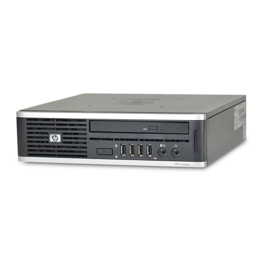
Product Features Standard Configuration Features The HP Compaq Ultra-Slim Desktop computer comes with features that may vary depending on the model. For a complete listing of the hardware and software installed in the computer, run the diagnostic utility (included on some computer models only). Figure 1-1 Ultra-Slim Desktop ENWW... -
Page 8: Front Panel Components
Front Panel Components Drive configuration may vary by model. Figure 1-2 Front Panel Components Table 1-1 Front Panel Components Optical Drive System Power LED SD Media Card Reader (optional) Headphone Connector NOTE: When a device is plugged into the Microphone/Headphone Connector, a dialog box will pop up asking if you want to use the connector for a microphone line Line-In device or a headphone. -
Page 9: Rear Panel Components
Rear Panel Components Figure 1-3 Rear Panel Components Table 1-2 Rear Panel Components Line-Out Connector for powered audio devices (green) PS/2 Keyboard Connector (purple) Universal Serial Bus (USB) (6) DisplayPort Monitor Connector VGA Monitor Connector (blue) NOTE: Arrangement and number of connectors may vary by model. When a device is plugged into the blue Line-In Audio Connector, a dialog box will pop up asking if you want to use the connector for a line-in device or a microphone. -
Page 10: Keyboard
Keyboard Figure 1-4 Keyboard Components Table 1-3 Keyboard Components Function Keys Editing Keys Status Lights Numeric Keys Arrow Keys Ctrl Keys Application Key Windows Logo Keys Alt Keys Keys available in select geographic regions. Using the Windows Logo Key Use the Windows Logo key in combination with other keys to perform certain functions available in the Windows operating system. - Page 11 Table 1-4 Windows Logo Key Functions (continued) Windows Logo Key Windows Logo Key + Windows Logo Key + Shift + Windows Logo Key + Windows Logo Key + Windows Logo Key + Windows Logo Key + Ctrl Windows Logo Key + Windows Logo Key + Windows Logo Key + Windows Logo Key +...
-
Page 12: Serial Number Location
Table 1-4 Windows Logo Key Functions (continued) Windows Logo Key + (on numpad) Windows Logo Key + (on numpad) Serial Number Location Each computer has a unique serial number and a product ID that are located on the top of the computer when it is in the tower configuration. -
Page 13: Hardware Upgrades
Hardware Upgrades Serviceability Features The computer includes features that make it easy to upgrade and service. No tools are needed for most of the installation procedures described in this chapter. Warnings and Cautions Before performing upgrades be sure to carefully read all of the applicable instructions, cautions, and warnings in this guide. -
Page 14: Connecting The Power Cord
Connecting the Power Cord When connecting the power supply, it is important to follow the steps below to ensure the power cord does not pull free from the computer. Connect the round end of the power cord to the power supply connector on the rear of the computer (1). -
Page 15: Removing The Computer Access Panel
Removing the Computer Access Panel To access internal components, you must remove the access panel: Remove/disengage any security devices that prohibit opening the computer. Remove all removable media, such as compact discs or USB flash drives, from the computer. Turn off the computer properly through the operating system, then turn off any external devices. Disconnect the power cord from the power outlet and disconnect any external devices. -
Page 16: Replacing The Computer Access Panel
Replacing the Computer Access Panel Align the tabs on the panel with the slots on the chassis then slide the panel towards the front of the chassis until it stops (1). Tighten the thumbscrew to secure the access panel (2). Figure 2-3 Replacing the Computer Access Panel Chapter 2 Hardware Upgrades... -
Page 17: Removing And Replacing The Front Bezel
Removing and Replacing the Front Bezel Remove/disengage any security devices that prohibit opening the computer. Remove all removable media, such as compact discs or USB flash drives, from the computer. Turn off the computer properly through the operating system, then turn off any external devices. Disconnect the power cord from the power outlet and disconnect any external devices. - Page 18 To replace the front bezel: Insert the three hooks on the bottom side of the bezel into the rectangular holes on the chassis (1) then rotate the top side of the bezel onto the chassis (2) and snap it into place. Figure 2-5 Replacing the Front Bezel Replace the access panel.
-
Page 19: Removing A Bezel Blank
Removing a Bezel Blank On some models, there is a bezel blank covering the external drive bay that needs to be removed before installing a drive. To remove a bezel blank: Remove the front bezel. Push the two retaining tabs that hold the bezel blank in place towards the outer left edge of the bezel (1) and pull the bezel blank inwards to remove it (2). -
Page 20: Changing From Desktop To Tower Configuration
Changing from Desktop to Tower Configuration Remove/disengage any security devices that prohibit opening the computer. Remove all removable media, such as compact discs or USB flash drives, from the computer. Turn off the computer properly through the operating system, then turn off any external devices. Disconnect the power cord from the power outlet and disconnect any external devices. -
Page 21: Installing Additional Memory
Installing Additional Memory The computer comes with double data rate 3 synchronous dynamic random access memory (DDR3- SDRAM) small outline dual inline memory modules (SODIMMs). SODIMMs The memory sockets on the system board can be populated with up to two industry-standard SODIMMs. These memory sockets are populated with at least one preinstalled SODIMM. -
Page 22: Populating Sodimm Sockets
Populating SODIMM Sockets There are two SODIMM sockets on the system board, with one socket per channel. The sockets are labeled XMM1 and XMM3. The XMM1 socket operates in memory channel A. The XMM3 socket operates in memory channel B. Figure 2-8 SODIMM Socket Locations Table 2-1... -
Page 23: Installing Sodimms
Installing SODIMMs CAUTION: You must disconnect the power cord and wait approximately 30 seconds for the power to drain before adding or removing memory modules. Regardless of the power-on state, voltage is always supplied to the memory modules as long as the computer is plugged into an active AC outlet. Adding or removing memory modules while voltage is present may cause irreparable damage to the memory modules or system board. - Page 24 If you are adding a second SODIMM, remove the SODIMM from the top XMM1 socket to access the bottom XMM3 socket. Press outward on the two latches on each side of the SODIMM (1) then pull the SODIMM out of the socket (2). Figure 2-9 Removing a SODIMM Slide the new SODIMM into the socket at approximately a 30°...
-
Page 25: Replacing The Optical Drive
If the computer was on a stand, replace the stand. Reconnect the power cord and turn on the computer. Lock any security devices that were disengaged when the computer cover or access panel was removed. The computer automatically recognizes the additional memory when you turn on the computer. Replacing the Optical Drive The Ultra-Slim Desktop uses a slimline Serial ATA (SATA) optical drive. -
Page 26: Preparing The New Optical Drive
Preparing the New Optical Drive Before the new optical drive can be used, the release latch must be attached. Peel the backing off the adhesive on the release latch. Without allowing the release latch to touch the optical drive, carefully align the holes on the release latch with the pins on the side of the optical drive. - Page 27 Slide the optical drive through the front bezel all the way into the bay so that it locks in place (1), then connect the cable to the rear of the drive (2). Figure 2-13 Installing the Optical Drive Replace the access panel. If the computer was on a stand, replace the stand.
-
Page 28: Replacing The Hard Drive
Replacing the Hard Drive NOTE: The Ultra-Slim Desktop supports only 2.5-inch Serial ATA (SATA) internal hard drives; parallel ATA (PATA) internal hard drives are not supported. Before you remove the old hard drive, be sure to back up the data from the old hard drive so that you can transfer the data to the new hard drive. - Page 29 Lift the hard drive carrier straight up and out of the chassis. Figure 2-15 Removing the Hard Drive Carrier Remove the four guide screws from the sides of the hard drive carrier. Figure 2-16 Removing the Guide Screws Lift the hard drive up to the top of the carrier (1) and slide the drive out of the carrier (2). Figure 2-17 Removing the Hard Drive from the Carrier ENWW...
- Page 30 Position the hard drive so that the top of the hard drive is up against the top of the carrier (1) so that the circuit board on the bottom of the hard drive does not come in contact wit the tabs on the bottom of the carrier, then slide the new hard drive into the carrier (2).
- Page 31 To place the hard drive carrier back in the chassis, align the guide screws with the slots on the drive bay, drop the carrier straight down into the drive bay (1), and press the handle on the carrier all the way down (2) so that the drive is properly seated and locked in place. Figure 2-20 Installing the Hard Drive Carrier Replace the optical drive and reconnect the cable on the back of the optical drive.
-
Page 32: Installing And Removing A Port Cover
Installing and Removing a Port Cover An optional rear port cover is available for the computer. To install the port cover: Thread the cables through the bottom hole on the port cover (1) and connect the cables to the rear ports on the computer. -
Page 33: Appendix A Specifications
Specifications Table A-1 Specifications Desktop Dimensions (in the desktop position) Height Width Depth (depth will increase if the computer is equipped with a port security bracket) Approximate Weight Weight Supported (maximum distributed load in desktop position) Temperature Range (values subject to change with increasing altitude above sea level) Operating Nonoperating... - Page 34 Table A-1 Specifications (continued) Rated Input Current (maximum) This system utilizes an active power factor corrected external power supply. This allows the system to pass the CE mark requirements for use in the countries of the European Union. The active power factor corrected power supply also has the added benefit of not requiring an input voltage range select switch.
-
Page 35: Battery Replacement
Battery Replacement The battery that comes with the computer provides power to the real-time clock. When replacing the battery, use a battery equivalent to the battery originally installed in the computer. The computer comes with a 3-volt lithium coin cell battery. WARNING! The computer contains an internal lithium manganese dioxide battery. - Page 36 NOTE: On some computer models, it may be necessary to remove an internal component to gain access to the battery. Depending on the type of battery holder on the system board, complete the following instructions to replace the battery. Type 1 Lift the battery out of its holder.
- Page 37 Insert the new battery and position the clip back into place. Figure B-3 NOTE: After the battery has been replaced, use the following steps to complete this procedure. Replace the access panel. If the computer was on a stand, replace the stand. Reconnect the power cord and turn on the computer.
-
Page 38: Appendix C Security Lock Provisions
Security Lock Provisions NOTE: For information on data security features, refer to the Desktop Management Guide and the HP ProtectTools Security Manager Guide (some models) at http://www.hp.com. The security locks displayed below and on the following pages can be used to secure the computer. Installing a Security Lock HP/Kensington MicroSaver Security Cable Lock There are two cable lock slots on the rear of the computer. -
Page 39: Padlock
Figure C-2 Installing a Cable with a Port Cover Installed Padlock Figure C-3 Installing a Padlock ENWW Installing a Security Lock... -
Page 40: Hp Business Pc Security Lock
HP Business PC Security Lock Fasten the security cable by looping it around a stationary object. Figure C-4 Securing the Cable to a Fixed Object Thread the keyboard and mouse cables through the lock. Figure C-5 Threading the Keyboard and Mouse Cables Appendix C Security Lock Provisions ENWW... -
Page 41: Front Bezel Security
Screw the lock to the chassis using the screw provided. Figure C-6 Attaching the Lock to the Chassis Insert the plug end of the security cable into the lock (1) and push the button in (2) to engage the lock. Use the key provided to disengage the lock. Figure C-7 Engaging the Lock Front Bezel Security... - Page 42 Disconnect the power cord from the power outlet and disconnect any external devices. CAUTION: Regardless of the power-on state, voltage is always present on the system board as long as the system is plugged into an active AC outlet. You must disconnect the power cord to avoid damage to the internal components of the computer.
- Page 43 Install the security screw through the middle front bezel release tab and into the chassis to secure the front bezel in place. Figure C-9 Installing the Front Bezel Security Screw Replace the access panel. If the computer was on a stand, replace the stand. Reconnect the power cord and turn on the computer.
-
Page 44: Appendix D Electrostatic Discharge
Electrostatic Discharge A discharge of static electricity from a finger or other conductor may damage system boards or other static-sensitive devices. This type of damage may reduce the life expectancy of the device. Preventing Electrostatic Damage To prevent electrostatic damage, observe the following precautions: ●... -
Page 45: Appendix E Computer Operating Guidelines, Routine Care And Shipping Preparation
Computer Operating Guidelines, Routine Care and Shipping Preparation Computer Operating Guidelines and Routine Care Follow these guidelines to properly set up and care for the computer and monitor: ● Keep the computer away from excessive moisture, direct sunlight, and extremes of heat and cold. ●... -
Page 46: Optical Drive Precautions
Optical Drive Precautions Be sure to observe the following guidelines while operating or cleaning the optical drive. Operation ● Do not move the drive during operation. This may cause it to malfunction during reading. ● Avoid exposing the drive to sudden changes in temperature, as condensation may form inside the unit. -
Page 47: Index
Index access panel locking and unlocking 32 removing 9 replacing 10 application key 4 audio connectors 2 battery replacement 29 bezel, removing 11 cable lock 32 components front panel 2 keyboard 4 rear panel 3 computer changing from desktop to tower 14 features 1 operating guidelines 39... - Page 48 power supply operating voltage range 27 product ID location 6 rear panel components 3 release latch attaching optical drive 20 removing access panel 9 battery 29 bezel blanks 13 front bezel 11 hard drive 22 optical drive 19 port cover 26 RJ-45 connector 3 security cable lock 32...