Table of Contents
Advertisement
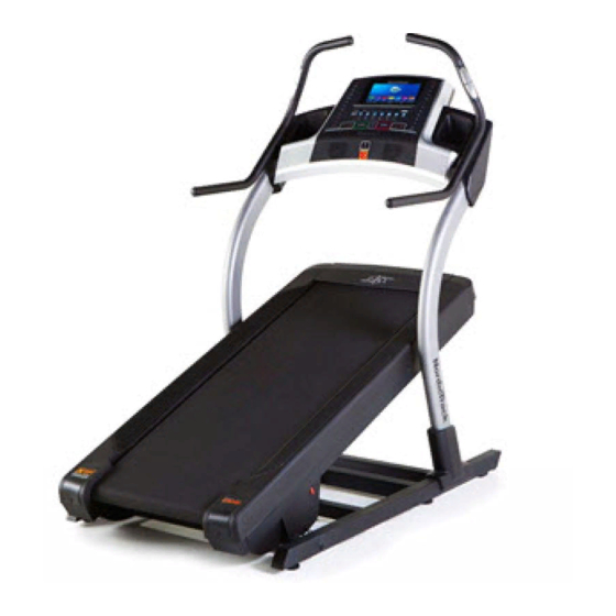
www.nordictrack.com
Model No. 24928.0
Serial No.
Write the serial number in the space
above for reference.
ACTIVATE YOUR
WARRANTY
To register your product and
activate your warranty today, go
to www.nordictrackservice.com/
registration.
CUSTOMER CARE
For service at any time, go to
www.nordictrackservice.com.
Or call 1-800-TO-BE-FIT
(1-800-862-3348)
Mon.–Fri. 6 a.m.–6 p.m. MT
Sat. 8 a.m.–12 p.m. MT
Please do not contact the store.
CAUTION
Read all precautions and instruc-
tions in this manual before using
this equipment. Save this manual
for future reference.
Serial
Number
Decal
USER'S MANUAL
Advertisement
Table of Contents

Related Manuals for NordicTrack 24928.0


Summary of Contents for NordicTrack 24928.0
- Page 1 USER’S MANUAL Model No. 24928.0 Serial No. Write the serial number in the space above for reference. Serial Number Decal ACTIVATE YOUR WARRANTY To register your product and activate your warranty today, go to www.nordictrackservice.com/ registration. CUSTOMER CARE For service at any time, go to www.nordictrackservice.com.
-
Page 2: Table Of Contents
TABLE OF CONTENTS WARNING DECAL PLACEMENT ............. . .2 IMPORTANT PRECAUTIONS . -
Page 3: Important Precautions
IMPORTANT PRECAUTIONS WARNING: To reduce the risk of burns, fire, electric shock, or injury to persons, read all important precautions and instructions in this manual and all warnings on your incline trainer before using your incline trainer. ICON assumes no responsibility for personal injury or property damage sustained by or through the use of this product. - Page 4 19. The incline trainer is capable of high speeds. 23. Never insert any object into any opening on Adjust the speed in small increments to the incline trainer. avoid sudden jumps in speed. 24. Inspect and properly tighten all parts of the 20.
- Page 6 STANDARD SERVICE PLANS...
-
Page 7: Before You Begin
BEFORE YOU BEGIN Thank you for selecting the revolutionary reading this manual, please see the front cover of this NORDICTRACK X9I INTERACTIVE INCLINE manual. To help us assist you, note the product model ® TRAINER. The X9I INTERACTIVE INCLINE TRAINER number and serial number before contacting us. -
Page 8: Part Identification Chart
PART IDENTIFICATION CHART Use the drawings below to identify small parts used for assembly. The number in parentheses below each draw- ing is the key number of the part, from the PART LIST near the end of this manual. The number following the key number is the quantity used for assembly. -
Page 9: Assembly
ASSEMBLY • Assembly requires two persons. • To identify small parts, see page 8. • Place all parts in a cleared area and remove the • Assembly requires the following tools: packing materials. Do not dispose of the packing materials until you finish all assembly steps. the included hex keys •... - Page 10 3. Remove the four 3/8" x 2 3/4" Screws (22) from the Uprights (83). Save the screws. 4. Set the Uprights (83) on the Base (74). Make sure that the hole with the Upright Wire (75) is on the right side. Attach the right Upright (83) to the Base (74) with four of the 3/8"...
- Page 11 5. Connect the Base Wire (52) to the Upright Wire (75). See the inset drawing. The connectors should slide together easily and snap into place. If they do not, turn one connector and try again. IF YOU DO NOT CONNECT THE CON- NECTORS PROPERLY, THE CONSOLE MAY BECOME DAMAGED WHEN YOU TURN ON Hole...
- Page 12 7. Slide the Right Inside Upright Cover (70) against the lower end of the right Upright (83). Press the Right Outside Upright Cover (71) against the Right Inside Upright Cover until it snaps into place. Make sure that the wires are not pinched.
-
Page 13: The Chest Heart Rate Monitor
THE CHEST HEART RATE MONITOR HOW TO PUT ON THE HEART RATE MONITOR • Do not expose the heart rate monitor to direct sun- light for extended periods of time; do not expose it to The heart rate temperatures above 122° F (50° C) or below 14° F monitor consists of (-10°... -
Page 14: Operation And Adjustment
OPERATION AND ADJUSTMENT HOW TO CONNECT THE POWER CORD nominal 120-volt circuit capable of carrying 15 or more amps. To avoid overloading the circuit, do Use a Surge Suppressor not plug other electrical devices, except for low- power devices such as cell phone chargers, into Your incline trainer, like other electronic equipment, the surge suppressor or into an outlet on the same circuit. - Page 15 CONSOLE DIAGRAM MAKE YOUR FITNESS GOALS A REALITY WITH FEATURES OF THE CONSOLE IFIT.COM The advanced incline trainer console offers an array of With your new iFit-enabled fitness equipment, you can features designed to make your workouts more effec- use an array of features on iFit.com to make your fit- tive and enjoyable.
- Page 16 HOW TO TURN ON THE POWER HOW TO USE THE TOUCH SCREEN IMPORTANT: If the incline trainer has been The console features a tablet with a full-color touch exposed to cold temperatures, allow it to warm to screen. The following information will help you become room temperature before you turn on the power.
- Page 17 HOW TO SET UP THE CONSOLE The console is now ready for you to begin working out. The following pages explain the various workouts and Before using the incline trainer for the first time, set up other features that the console offers. the console.
- Page 18 HOW TO USE THE MANUAL MODE of the numbered Incline/Decline buttons. Each time you press one of the buttons, the incline will gradu- 1. Insert the key into the console. ally change until it reaches the selected incline setting. See HOW TO TURN ON THE POWER on page 16.
- Page 19 7. Turn on the fan if desired. If desired, adjust the volume by pressing the volume buttons on the console. The fan features several speed To pause the workout, touch one of the menu but- settings and an auto mode. tons or press the Stop button on the console.
- Page 20 HOW TO USE AN ONBOARD WORKOUT If the speed and/or incline settings are too high or too low at any time during the workout, you can 1. Insert the key into the console. override the settings by pressing the Speed or Incline buttons.
- Page 21 HOW TO USE A SET-A-GOAL WORKOUT The workout will function in the same way as the manual mode (see page 18). 1. Insert the key into the console. The workout will continue until you reach the goal See HOW TO TURN ON THE POWER on that you set.
- Page 22 HOW TO USE A PULSE WORKOUT 5. Start the workout. Pulse workouts automatically control the speed and Touch the Start Workout button on the screen to incline of the incline trainer to keep your heart rate near start the workout. A moment after you touch the a target level while you exercise.
- Page 23 HOW TO USE AN IFIT WORKOUT Before some workouts will download, you must add them to your schedule on iFit.com. Note: To use an iFit workout, you must have access For more information about the iFit workouts, to a wireless network (see HOW TO USE THE please see www.iFit.com.
- Page 24 HOW TO USE THE EQUIPMENT SETTINGS MODE IMPORTANT: You must still unplug the power cord after using the incline trainer. Set the 1. Select the settings main menu. update time for a time when you normally use the incline trainer and will be available to unplug the power cord after an update.
- Page 25 11. Enable or disable a passcode. Next, press the play button on your personal audio player. Adjust The console features a child-safety passcode, the volume level using the volume designed to prevent unauthorized users from using increase and decrease buttons on the incline trainer.
- Page 26 HOW TO USE THE MAINTENANCE MODE Note: Occasionally, a firmware update may cause your console to function slightly differently. These 1. Select the settings main menu. updates are always designed to improve your exer- cise experience. See step 1 on page 24. 4.
-
Page 27: Wireless Network Mode
HOW TO USE THE WIRELESS NETWORK MODE An information box will ask if you want to connect to the wireless network. Touch the Connect button The console features a wireless network mode that to connect to the network or touch the Cancel but- allows you to set up a wireless network connection. - Page 28 HOW TO USE A TABLET WITH THE CONSOLE HOW TO USE THE TABLET HOLDER Note: To connect your tablet to the console, you must Secure your tablet to the console while you use the have access to a wireless network (see page 27). An incline trainer.
-
Page 29: How To Move The Incline Trainer
HOW TO MOVE THE INCLINE TRAINER Before moving the incline trainer, insert the key Carefully roll the incline trainer on the wheels to the into the console, raise the incline to the maximum desired location, and then lower it to the level position. incline level, remove the key, and unplug the power CAUTION: To reduce the risk of injury, use extreme cord. -
Page 30: Troubleshooting
TROUBLESHOOTING Most incline trainer problems can be solved by fol- SYMPTOM: The console displays remain lit when lowing the simple steps below. Find the symptom you remove the key from the console that applies, and follow the steps listed. If further assistance is needed, see the front cover of this a. - Page 31 SYMPTOM: The walking belt slows when walked on SYMPTOM: The walking belt is off-center or slips when walked on a. Use only a surge suppressor that meets all of the a. If the walking belt is off-center, first adjust specifications described on page 14. the incline to 40 percent.
- Page 32 SYMPTOM: The iFit mode does not function SYMPTOM: The incline trainer will not connect to correctly your tablet a. If the iFit mode is not functioning correctly, make a. Make sure that the wireless settings on the console sure that the incline trainer has the most current are correct (see page 27).
-
Page 33: Exercise Guidelines
EXERCISE GUIDELINES Burning Fat—To burn fat effectively, you must exer- WARNING: cise at a low intensity level for a sustained period of Before beginning this time. During the first few minutes of exercise, your or any exercise program, consult your physi- body uses carbohydrate calories for energy. -
Page 34: Part List
PART LIST Model No. 24928.0 R1213A Key No. Qty. Description Key No. Qty. Description 3/8" x 5 1/4" Screw Cushion 3/8" x 3 3/4" Screw Base Wire 3/8" Star Washer Rubber Cushion #8 x 3/4" Tek Screw Chest Strap #8 x 3/4" Screw Electronics Cover 3/8"... -
Page 35: Exploded Drawing
EXPLODED DRAWING A Model No. 24928.0 R1213A... - Page 36 EXPLODED DRAWING B Model No. 24928.0 R1213A...
- Page 37 EXPLODED DRAWING C Model No. 24928.0 R1213A...
- Page 38 EXPLODED DRAWING D Model No. 24928.0 R1213A...
- Page 39 EXPLODED DRAWING E Model No. 24928.0 R1213A...
-
Page 40: Ordering Replacement Parts
ORDERING REPLACEMENT PARTS To order replacement parts, please see the front cover of this manual. To help us assist you, be prepared to provide the following information when contacting us: • the model number and serial number of the product (see the front cover of this manual) •...