HP ProBook 6455b Maintenance And Service Manual
Notebook pc
Hide thumbs
Also See for ProBook 6455b:
- Maintenance and service manual (204 pages) ,
- Specification (41 pages) ,
- User manual (181 pages)
Table of Contents
Advertisement
Quick Links
Download this manual
See also:
User Manual
Advertisement
Table of Contents

Related Manuals for HP ProBook 6455b


Summary of Contents for HP ProBook 6455b
- Page 1 HP ProBook 6455b Notebook PC HP ProBook 6555b Notebook PC HP ProBook 6450b Notebook PC HP ProBook 6550b Notebook PC Maintenance and Service Guide...
- Page 2 Microsoft Corporation. The information contained herein is subject to change without notice. The only warranties for HP products and services are set forth in the express warranty statements accompanying such products and services. Nothing herein should be construed as constituting an additional warranty.
- Page 3 Safety warning notice WARNING! To reduce the possibility of heat-related injuries or of overheating the device, do not place the device directly on your lap or obstruct the device air vents. Use the device only on a hard, flat surface. Do not allow another hard surface, such as an adjoining optional printer, or a soft surface, such as pillows or rugs or clothing, to block airflow.
- Page 4 Safety warning notice...
-
Page 5: Table Of Contents
Table of contents 1 Product description ......................1 2 External component identification ................... 14 Identifying the hardware ......................14 Top components ........................15 Display components ....................15 Keys ........................16 Pointing devices ...................... 18 Buttons and fingerprint reader ................... 19 Lights ........................ - Page 6 Cables and connectors ................73 Drive handling ..................73 Grounding guidelines ....................74 Electrostatic discharge damage ..............74 Packaging and transporting guidelines ........75 Workstation guidelines .............. 75 Equipment guidelines ..............76 Component replacement procedures ..................77 Service tag ......................77 Computer feet ......................
- Page 7 Starting Computer Setup ..................152 Using Computer Setup ................... 152 Navigating and selecting in Computer Setup ..........152 Restoring factory settings in Computer Setup ..........153 Computer Setup menus ..................154 File menu ....................154 Diagnostics menu ................... 155 System Configuration menu ..............156 Computer Setup in Windows Vista ..................
- Page 8 Recovering ......................184 Backup and recovery in Windows Vista .................. 185 Overview ......................185 Backing up your information ................... 185 Performing a recovery .................... 186 Using the Windows recovery tools ................187 Using f11 ......................187 Using a Windows Vista operating system DVD (purchased separately) ......188 Backup and recovery in Windows XP ..................
-
Page 9: Product Description
6555b Notebook Notebook Notebook Notebook √ Product Name HP ProBook 6555b Notebook PC √ HP ProBook 6455b Notebook PC √ HP ProBook 6550b Notebook PC √ HP ProBook 6450b Notebook PC √ √ Processor AMD Phenom II Quad Core Mobile N970 2.2-GHz processor (35W, 2-... - Page 10 Category Description HP ProBook HP ProBook HP ProBook ProBook 6455b 6550b 6450b 6555b Notebook Notebook Notebook Notebook √ √ AMD Phenom II Dual Core Mobile N620 2.8-GHz processor (35W, 2- MB L2 cache) √ √ AMD Turion II Dual Core Mobile N530 2.5-GHz processor (25W, 2-...
- Page 11 UMA graphics √ √ √ √ Supports dual-display ports through docking station √ √ √ √ Panels Supports HP Privacy Filter √ √ √ √ Supports 16×9 aspect ratio display panels √ √ 15.6-in, HD, LED, AntiGlare (AG) (1366×768) √...
- Page 12 Category Description HP ProBook HP ProBook HP ProBook ProBook 6455b 6550b 6450b 6555b Notebook Notebook Notebook Notebook √ 14.0-in, HD, LED, BV (1366x768) WWAN √ 14.0-in, HD+, LED, AG (1600×900) WWAN √ √ 14.0” HD LED AG with webcam (1366x768) √...
- Page 13 (2.50-in) hard drives and solid-state drives √ √ √ √ Customer-accessible √ √ √ √ Supports HP 3D DriveGuard √ √ √ √ Supports the following hard drives: ● 500-GB, 7200-rpm ● 320-GB, 7200-rpm SED ● 320-GB, 7200-rpm ●...
- Page 14 Category Description HP ProBook HP ProBook HP ProBook ProBook 6455b 6550b 6450b 6555b Notebook Notebook Notebook Notebook √ √ √ √ Integrated mono digital microphone only on computer models not equipped with a webcam √ √ √ √ Audio IDT 92HD75B high-definition audio √...
- Page 15 Secure Digital (SD) Memory Card ● Secure Digital (SD) High Capacity Memory Card ● Secure Digital (SD) HS Memory Card ● xD-Picture Card √ √ √ √ Docking Docking supported through the HP Advanced 120W Docking Station and HP 90W Docking Station...
- Page 16 √ √ Taps enabled as default √ √ Power 90-W HP Smart Adapter requirements √ √ 90-W PFC EM HP Smart Adapter (India only) √ √ 90-W Smart Adapter (discrete only) √ √ 90-W Smart Adapter (UMA only) √ √...
- Page 17 √ √ Supports 6-cell Lithium Ion (Li Ion) battery (55 WH) √ √ √ √ Supports 9-cell Li Ion battery (93 NOTE: Does not support HP Fast Charge. √ √ √ √ Supports 6-cell Long Life Battery √ √ √...
- Page 18 Category Description HP ProBook HP ProBook HP ProBook ProBook 6455b 6550b 6450b 6555b Notebook Notebook Notebook Notebook √ √ √ √ Operating Preinstalled without system Microsoft® Office: ● Windows® 7 Home Premium ● Windows 7 Home Premium 32 ● Windows 7 Pro 64 ●...
- Page 19 Category Description HP ProBook HP ProBook HP ProBook ProBook 6455b 6550b 6450b 6555b Notebook Notebook Notebook Notebook √ √ √ √ Preinstalled with Microsoft Office: ● Windows 7 Home Basic 32 ● Windows 7 Home Premium 64 ● Windows 7 Home Premium 32 ●...
- Page 20 Category Description HP ProBook HP ProBook HP ProBook ProBook 6455b 6550b 6450b 6555b Notebook Notebook Notebook Notebook √ √ √ √ Restore Media (OSDVD): ● Windows 7 Home Basic 32 ● Windows 7 Home Premium 64 ● Windows 7 Home Premium 32 ●...
- Page 21 Category Description HP ProBook HP ProBook HP ProBook ProBook 6455b 6550b 6450b 6555b Notebook Notebook Notebook Notebook √ √ √ √ Web-only support: ● Windows 7 Enterprise 64 ● Windows 7 Enterprise 32 ● Windows 7 Ultimate 64 ● Windows 7 Ultimate 32 ●...
-
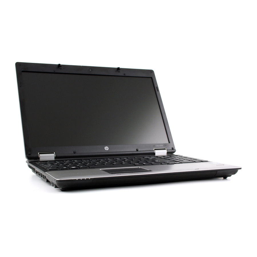
Page 22: External Component Identification
External component identification Identifying the hardware Components included with the computer may vary by region and model. The illustrations in this chapter identify the standard features on most computer models. To see a list of hardware installed in the computer, follow these steps: For Windows 7 and Windows Vista: Select Start >... -
Page 23: Top Components
Top components Display components NOTE: Your computer may look slightly different from the illustration in this section. Item Component Description WWAN antennas (2)* Send and receive wireless signals to communicate with wireless wide-area networks (WWAN). Internal microphones (1 or 2, varying by computer model) Record sound. -
Page 24: Keys
Keys NOTE: Refer to the illustration that most closely matches your computer. Item Component Description Displays system information when pressed in combination with the key. Executes frequently used system functions when pressed in combination with a function key or the key. - Page 25 Item Component Description Displays system information when pressed in combination with the key. Executes frequently used system functions when pressed in combination with a function key or the key. Windows logo key Displays the Windows Start menu. Windows applications key Displays a shortcut menu for items beneath the pointer.
-
Page 26: Pointing Devices
Pointing devices Item Component Description Pointing stick (select models only)* Moves the pointer and selects or activates items on the screen. Left pointing stick button (select models only)* Functions like the left button on an external mouse. TouchPad Moves the pointer and selects or activates items on the screen. -
Page 27: Buttons And Fingerprint Reader
Buttons and fingerprint reader NOTE: Refer to the illustration that most closely matches your computer. Item Component Description ● Power button When the computer is off, press the button to turn on the computer. ● When the computer is on, press the button to shut down the computer. - Page 28 Item Component Description ● QuickLook button When the computer is off, press the button to open HP QuickLook. ● When the computer is on, press the button to open Software Setup. NOTE: If Software Setup is not available, the default Web browser opens.
- Page 29 Performance and Maintenance > Power Options. ● QuickLook button When the computer is off, press the button to open HP QuickLook. ● When the computer is on, press the button to open Software Setup. NOTE: If Software Setup is not available, the default Web browser opens.
-
Page 30: Lights
Component Description ● Wireless lights (2)* Blue: An integrated wireless device, such as a WLAN device, the HP Mobile Broadband Module (select models only), and/or a Bluetooth device, is ● Amber: All wireless devices are off. ● Power lights (2)†... - Page 31 Item Component Description ● QuickLook light On: The computer is on. ● Off: The computer is off or in the Sleep state (Windows 7 and Windows Vista) or Standby (Windows XP) or Hibernation. QuickWeb light On: The Web browser is in use. Caps lock light On: Caps lock is on.
- Page 32 Component Description ● Wireless lights (2)* Blue: An integrated wireless device, such as a WLAN device, the HP Mobile Broadband Module (select models only), and/or a Bluetooth device, is ● Amber: All wireless devices are off. ● Power lights (2)†...
- Page 33 Item Component Description (11) Volume up light Blinking: The volume up button is being used to increase the speaker volume. *The 2 wireless lights display the same information. The light on the wireless button is visible only when the computer is open. The wireless light on the front of the computer is visible whether the computer is open or closed.
-
Page 34: Front Components
Component Description ● Wireless light Blue: An integrated wireless device, such as a wireless local area network (WLAN) device, the HP Mobile Broadband Module (select models only), and/or a Bluetooth device, is on. ● Amber: All wireless devices are off. -
Page 35: Right-Side Components
Right-side components NOTE: Refer to the illustration that most closely matches your computer. Item Component Description Media Card Reader Supports the following optional digital card formats: ● Memory Stick ● Memory Stick Pro ● Memory Stick Duo (adapter required) ● Memory Stick Duo Pro (adapter required) ●... - Page 36 Item Component Description Media Card Reader Supports the following optional digital card formats: ● Memory Stick ● Memory Stick Pro ● Memory Stick Duo (adapter required) ● Memory Stick Duo Pro (adapter required) ● MultiMediaCard ● MultiMediaCard Plus ● Secure Digital (SD) Memory Card ●...
-
Page 37: Left-Side Components
Left-side components NOTE: Refer to the illustration that most closely matches your computer. Item Component Description Vent Enables airflow to cool internal components. NOTE: The computer fan starts up automatically to cool internal components and prevent overheating. It is normal for the internal fan to cycle on and off during routine operation. - Page 38 Item Component Description Vent Enables airflow to cool internal components. NOTE: The computer fan starts up automatically to cool internal components and prevent overheating. It is normal for the internal fan to cycle on and off during routine operation. DisplayPort Connects an optional digital display device such as a high-performance monitor or projector.
-
Page 39: Rear Components
Rear components NOTE: Your computer may look slightly different from the illustration in this section. Item Component Description Security cable slot Attaches an optional security cable to the computer. NOTE: The security cable is designed to act as a deterrent, but it may not prevent the computer from being mishandled or stolen. -
Page 40: Bottom Components
Bottom components Item Component Description Battery bay Holds the battery. SIM slot Contains a wireless subscriber identity module (SIM) (select models only). The SIM slot is located inside the battery bay. Battery release latch Releases the battery from the battery bay. Docking connector Connects an optional docking device. - Page 41 Item Component Description HP Mobile Broadband Module compartment Contains an HP Mobile Broadband Module (select models only). NOTE: To prevent an unresponsive system, replace the wireless module only with a wireless module authorized for use in the computer by the governmental agency that regulates wireless devices in your country or region.
-
Page 42: Illustrated Parts Catalog
Illustrated parts catalog Service tag When ordering parts or requesting information, provide the computer serial number and model description provided on the service tag: NOTE: The computer battery must be removed to access the service tag. (1) Product name: This is the product name affixed to the front of the device. (2) Serial number (s/n): This is an alphanumeric identifier that is unique to each product. - Page 43 Service tag...
-
Page 44: Computer Major Components
Computer major components Item Description Spare part number Display assembly (includes 3 WLAN antenna transceivers and cables, microphones, nameplate, and logo): Chapter 3 Illustrated parts catalog... - Page 45 Item Description Spare part number For use only on HP Compaq 6555b and 6550b Notebook PC models: 15.6-in HD LED AG (1366×768) 613361-001 15.6-in HD+ LED WVA AG (1600×900) 613366-001 15.6-in HD LED AG (1366×768) with WWAN capability (includes 2 WWAN antenna...
- Page 46 Item Description Spare part number For use only on computer models equipped with a 14.0-in display assembly 613341-001 Power button board (includes cable) 613310-001 Keyboard (includes keyboard cable): For use only on computer models equipped with a 15.6-in display assembly, pointing stick, TouchPad, and numeric keypad: For use in Belgium 613385-A41...
- Page 47 Item Description Spare part number For use in the United Kingdom 613385-031 For use in the United States 613385-001 For use only on computer models equipped with a 15.6-in display assembly, TouchPad, and numeric keypad: For use in Belgium 613386-A41 For use in Bulgaria 613386-261 For use in the Czech Republic and Slovakia...
- Page 48 Item Description Spare part number For use in the United Kingdom 613386-031 For use in the United States 613386-001 For use only on computer models equipped with a 14.0-in display assembly, pointing stick, and TouchPad: For use in Belgium 613332-A41 For use in Bulgaria 613332-261 For use in Czech Republic and Slovakia...
- Page 49 Item Description Spare part number For use in the United Kingdom 613332-031 For use in the United States 613332-001 For use only on computer models equipped with a 14.0-in display assembly and TouchPad: For use in Belgium 613384-A41 For use in Bulgaria 613384-261 For use in Czech Republic and Slovakia 613384-A81...
- Page 50 Item Description Spare part number Palm rest: For use only on computer models equipped with a 15.6-in display assembly and a 613339-001 fingerprint reader (includes fingerprint reader board and cable) For use only on computer models equipped with a 15.6-in display assembly but not a 613340-001 fingerprint reader For use only on computer models equipped with a 14.0-in display assembly and a...
- Page 51 Heat sink (includes replacement thermal material): For use only on HP Compaq 6555b and 6455b computer models 613399-001 For use only on HP Compaq 6550b and 6450b computer models equipped with a graphics 613350-001 subsystem with discrete memory For use only on HP Compaq 6550b and 6450b computer models equipped with a graphics...
- Page 52 For use only on computer models equipped with a graphics subsystem with UMA memory 616790-001 and WWAN capability in the People's Republic of China For use only on HP Compaq 6550b and 6450b computer models: For use only on computer models equipped with an Intel HM57 graphics subsystem with 613296-001...
- Page 53 613347-001 (19) Processor (includes replacement thermal material): For use only on HP Compaq 6555b and 6455b computer models: AMD Phenom II Quad Core Mobile N970 2.2-GHz processor (35W, 2-MB L2 cache) 635496-001 AMD Phenom II Quad Core Mobile N950 2.1-GHz processor (35W, 2-MB L2 cache) 616346-001 AMD Phenom II Quad Core Mobile N930 2.0-GHz processor (35W, 2-MB L2 cache)
- Page 54 Item Description Spare part number Intel Core i7-620M 2.66-GHz processor (turbo up to 3.33-GHz), 4-MB L3 cache, 4 threads, 603010-001 Intel Core i5-580M 2.66-GHz processor (turbo up to 3.33-GHz), 3-MB L3 cache, 4 threads, 625825-001 Intel Core i5-560M 2.66-GHz processor (turbo up to 3.20-GHz), 3-MB L3 cache, 4 threads, 625824-001 Intel Core i5-540M 2.53-GHz processor (turbo up to 3.06-GHz), 3-MB L3 cache, 4 threads, 594646-001...
- Page 55 Item Description Spare part number (23) HSPA EV-DO WWAN module 531993-001 (24) WLAN module: Broadcom 4322 802.11 a/b/g WLAN module for use in Antigua and Barbuda, Barbados, 582564-001 Belize, Canada, the Cayman Islands, Guam, Puerto Rico, Trinidad and Tobago, the U.S. Virgin Islands, and the United States Broadcom 4322 802.11 a/b/g WLAN module for use in Afghanistan, Albania, Algeria, 582564-002...
- Page 56 9-cell, 93-WH battery 586031-001 6-cell, 55-WH battery 486296-001 6-cell, 51-WH battery (for use only on HP Compaq 6555b and 6455b computer models) 593578-001 6-cell, 51-WH battery (for use only on HP Compaq 6550b and 6450b computer models) 627971-001 6-cell, 47-WH battery (for use only on HP Compaq 6550b and 6450b computer models)
-
Page 57: Display Assembly Components
Display assembly components NOTE: Display assembly subcomponents are available only for standard display assemblies. Flush glass display assemblies are available only as hinge-up assemblies. Item Description Spare part number Display bezel: For use only on computer models equipped with a 15.6-in display assembly and a 613322-001 webcam For use only on computer models equipped with a 15.6-in display assembly but not a... - Page 58 Webcam module 611026-001 Display Hinge Kit (includes left and right display hinges): For use only on HP Compaq 6555b and 6545b computer models equipped with a 15.6- 583232-001 in display assembly For use only on HP Compaq 6555b and 6545b computer models equipped with a 14.0-...
-
Page 59: Cable Kit
Cable Kit Item Description Spare part number Cable Kit: 613352-001 TouchPad board cable Bluetooth module cable Modem module cable (includes RJ-11 connector) Cable Kit... -
Page 60: Mass Storage Devices
Mass storage devices Item Description Spare part number Hard drive (includes cable adapter, bracket, and 4 isolators): 500-GB, 7200-rpm 634919-001 320-GB, 7200-rpm 626978-001 and 603783-001 250-GB, 7200-rpm 635225-001 Hard Drive Hardware Kit (not illustrated, includes hard drive bracket and 4 screws) 630891-001 Solid-state drive (includes cable adapter, bracket, and 4 isolators): 128-GB solid-state drive... -
Page 61: Plastics Kit
Plastics Kit Item Description Spare part number Plastics Kit For use only on computer models equipped with a 15.6-in display assembly 613344-001 For use only on computer models equipped with a 14.0-in display assembly 613343-001 Includes: ExpressCard slot bezel Mass storage device cover (includes 2 captive screws) Memory module compartment cover (includes 1 captive screw) Bluetooth module compartment cover (includes 1 captive screw) Wireless module compartment cover (includes 2 captive screws) -
Page 62: Miscellaneous Parts
90-W PFC HP Smart adapter 609940-001 90-W PFC EM HP Smart adapter 609947-001 65-W PFC RC/V HP Smart adapter 609939-001 65-W PFC RC/V EM HP Smart adapter 609948-001 Power cord: For use in Argentina 490371-D01 For use in Brazil 490371-201... -
Page 63: Sequential Part Number Listing
Sequential part number listing Spare part number Description 449137-001 RTC battery for use only on HP Compaq 6550b and 6450b computer models 481089-001 RTC battery for use only on HP Compaq 6555b and 6454b computer models 486295-001 6-cell, 47-WH battery... - Page 64 Tuvalu, Uganda, Ukraine, the United Arab Emirates, the United Kingdom, Uruguay, Uzbekistan, Vanuatu, Venezuela, Vietnam, Yemen, Zaire, Zambia, and Zimbabwe 531993-001 HSPA EV-DO WWAN module 534043-001 Smart Card Reader for use only on HP Compaq 6550b and 6450b computer models (factory- installed on select models only) 537921-001 Bluetooth module NOTE: The Bluetooth module spare part kit does not include a Bluetooth module cable.
- Page 65 Display Cable Kit for use only on computer models equipped with a 14.0-in HD display assembly 583232-001 Display Hinge Kit for use only on HP Compaq 6555b and 6454b computer models equipped with a 15.6-in display assembly (includes left and right hinges)
- Page 66 Spare part number Description 594166-001 AMD Phenom II Dual Core processor N620 (2.8-GHz/35W/2 MB L2 cache) for use only on HP Compaq 6555b and 6455b computer models (includes replacement thermal material) 594168-001 AMD Phenom II Triple Core processor N830 (2.1-GHz/35W/1.5 MB L2 cache) for use only on HP...
- Page 67 Description 613295-001 Intel QM57 system board for use only on HP Compaq 6550b and 6450b computer models equipped with a graphics subsystem with UMA memory and WWAN capability in Russia and the People's Republic of China (includes replacement thermal material)
- Page 68 WWAN capability (includes 3 WLAN antenna transceivers and cables and 2 WWAN antenna transceivers and cables) 613327-001 Display hinges for use only on HP Compaq 6550b and 6540b computer models equipped with a 14.0-in display assembly 613328-001 Display hinges for use only on HP Compaq 6550b and 6540b computer models equipped with a 15.6-in display assembly...
- Page 69 Spare part number Description 613330-001 Base enclosure for use only on computer models equipped with a 14.0-in display assembly (includes 7 rubber feet and battery release latch) 613331-001 Base enclosure for use only on computer models equipped with a 15.6-in display assembly (includes 7 rubber feet and battery release latch) 613332-001 Keyboard for use only on computer models equipped with a 14.0-in display assembly with a...
- Page 70 Spare part number Description 613332-291 Keyboard for use only on computer models equipped with a 14.0-in display assembly with a pointing stick and TouchPad in Japan (includes keyboard cable) 613332-A41 Keyboard for use only on computer models equipped with a 14.0-in display assembly with a pointing stick and TouchPad in Belgium (includes keyboard cable) 613332-A81 Keyboard for use only on computer models equipped with a 14.0-in display assembly with a...
- Page 71 (includes cable) 613349-001 613350-001 Heat sink for use only on HP Compaq 6550b and 6450b computer models equipped with a graphics subsystem with discrete memory (includes replacement thermal material) 613351-001 Heat sink for use only on HP Compaq 6550b and 6450b computer models equipped with a...
- Page 72 613374-001 14.0-in, HD, LED, BV display assembly (1366 x 768) for use only on HP Compaq 6450b computer models not equipped with a webcam (includes 3 WLAN antenna transceivers and cables, 2 WWAN antenna transceivers and cables, microphones, nameplate, and logo) 613375-001 14.0-in, HD, LED, BV display assembly (1366 x 768) for use only on HP Compaq 6450b computer...
- Page 73 Spare part number Description 613382-001 14.0-in, HD+, LED, AG display assembly (1600 x 900) for use only on computer models equipped with a webcam and WWAN (includes 3 WLAN antenna transceivers and cables, 2 WWAN antenna transceivers and cables, microphones, nameplate, and logo) 613383-001 14.0-in, HD, LED, AG display assembly (1366 x 768) for use only on computer models equipped with a webcam and WWAN (includes 3 WLAN antenna transceivers and cables, 2 WWAN...
- Page 74 Spare part number Description 613384-291 Keyboard for use only on computer models equipped with a 14.0-in display assembly and TouchPad in Japan (includes keyboard cable) 613384-A41 Keyboard for use only on computer models equipped with a 14.0-in display assembly and TouchPad in Belgium (includes keyboard cable) 613384-A81 Keyboard for use only on computer models equipped with a 14.0-in display assembly and...
- Page 75 Spare part number Description 613385-091 Keyboard for use only on computer models equipped with a 15.6-in display assembly with a pointing stick, TouchPad, and a numeric keypad in Norway (includes keyboard cable) 613385-121 Keyboard for use only on computer models equipped with a 15.6-in display assembly with a pointing stick, TouchPad, and a numeric keypad in French Canada (includes keyboard cable) 613385-131 Keyboard for use only on computer models equipped with a 15.6-in display assembly with a...
- Page 76 Spare part number Description 613385-BG1 Keyboard for use only on computer models equipped with a 15.6-in display assembly and a pointing stick in Switzerland (includes keyboard cable) 613385-DD1 Keyboard for use only on computer models equipped with a 15.6-in display assembly with a pointing stick, TouchPad, and a numeric keypad in Iceland (includes keyboard cable) 613385-DJ1 Keyboard for use only on computer models equipped with a 15.6-in display assembly with a...
- Page 77 Keyboard for use only on computer models equipped with a 15.6-in display assembly, TouchPad, and a numeric keypad in Europe (includes keyboard cable) 613397-001 AMD UMA system board for use only on HP Compaq 6555b and 6455b computer models (includes replacement thermal material) 613398-001...
- Page 78 Spare part number Description 613584-001 Intel Core i3-370M (2.40-GHz, 3 MB L3 cache, 35W) for use only on HP Compaq 6550b and 6450b computer models (includes replacement thermal material) 613585-001 Intel Core i5-450M (2.40-GHz (turbo up to 2.66-GHz), 3 MB L3 cache, 4 threads, 35 W) for use...
- Page 79 Spare part number Description 626039-001 Intel Core i5-460M 2.53-GHz (turbo up to 2.80-GHz) processor (3-MB L3 cache, 4 threads, 35 W; includes replacement thermal material) 626978-001 320-GB, 7200-rpm hard drive (includes bracket) 627971-001 6-cell, 51-WH battery 628824-001 Modem module for use in all countries and regions except Australia and New Zealand NOTE: The modem module spare part kit does not include a modem module cable.
-
Page 80: Removal And Replacement Procedures
Removal and replacement procedures Preliminary replacement requirements Tools required You will need the following tools to complete the removal and replacement procedures: ● Flat-bladed screwdriver ● Phillips P0 screwdriver ● Phillips P1 screwdriver ● Torx T8 screwdriver Service considerations The following sections include some of the considerations that you must keep in mind during disassembly and assembly procedures. -
Page 81: Cables And Connectors
Cables and connectors CAUTION: When servicing the device, be sure that cables are placed in their proper locations during the reassembly process. Improper cable placement can damage the device. Cables must be handled with extreme care to avoid damage. Apply only the tension required to unseat or seat the cables during removal and insertion. -
Page 82: Grounding Guidelines
Grounding guidelines Electrostatic discharge damage Electronic components are sensitive to electrostatic discharge (ESD). Circuitry design and structure determine the degree of sensitivity. Networks built into many integrated circuits provide some protection, but in many cases, ESD contains enough power to alter device parameters or melt silicon junctions. -
Page 83: Packaging And Transporting Guidelines
Packaging and transporting guidelines Follow these grounding guidelines when packaging and transporting equipment: ● To avoid hand contact, transport products in static-safe tubes, bags, or boxes. ● Protect ESD-sensitive parts and assemblies with conductive or approved containers or packaging. ● Keep ESD-sensitive parts in their containers until the parts arrive at static-free workstations. -
Page 84: Equipment Guidelines
Equipment guidelines Grounding equipment must include either a wrist strap or a foot strap at a grounded workstation. ● When seated, wear a wrist strap connected to a grounded system. Wrist straps are flexible straps with a minimum of one megohm ±10% resistance in the ground cords. To provide proper ground, wear a strap snugly against the skin at all times. -
Page 85: Component Replacement Procedures
Component replacement procedures This chapter provides removal and replacement procedures. There are as many as 92 screws, in 11 different sizes, that must be removed, replaced, or loosened when servicing the computer. Make special note of each screw size and location during removal and replacement. -
Page 86: Computer Feet
Computer feet The computer feet are adhesive-backed rubber pads. The feet are included in the Rubber Kit, spare part number 613459-001. There are 7 rubber feet that attach to the base enclosure in the locations shown in the following illustration. Chapter 4 Removal and replacement procedures... -
Page 87: Battery
9-cell, 93-WH battery 586031-001 6-cell, 55-WH battery 486296-001 6-cell, 51-WH battery (for use only on HP Compaq 6550b and 6450b computer models) 627971-001 6-cell, 51-WH battery (for use only on HP Compaq 6555b and 6455b computer models) 593578-001 6-cell, 47-WH battery (for use only on HP Compaq 6550b and 6450b computer models) -
Page 88: Sim
Insert the battery into the battery bay until it is seated. The battery release latch automatically locks the battery into place. NOTE: The SIM is provided by the end user as a security measure for the WWAN module. The SIM should be removed, placed into a static-dissipative container, and then replaced when the computer is reassembled. -
Page 89: Bluetooth Module
Bluetooth module NOTE: The Bluetooth module spare part kit does not include a Bluetooth module cable. The Bluetooth module cable is included in the Cable Kit, spare part numbers 613352-001. Description Spare part number Bluetooth module 537921-001 Before removing the Bluetooth module, follow these steps: Shut down the computer. - Page 90 Release the Bluetooth module (1) by lifting the right side of the module out of the Bluetooth module compartment. Disconnect the Bluetooth module cable (2) from the Bluetooth module. Remove the Bluetooth module (3). Reverse this procedure to install the Bluetooth module. Chapter 4 Removal and replacement procedures...
-
Page 91: Mass Storage Device
Mass storage device NOTE: The mass storage device spare part kit includes a bracket. Description Spare part number Hard drive: 500-GB, 7200-rpm 634919-001 320-GB, 7200-rpm 626978-001 and 603783-001 250-GB, 7200-rpm 635225-001 Hard Drive Hardware Kit (not illustrated, includes hard drive bracket and 4 screws) 630891-001 Solid-state drive: 128-GB, 2.5-in solid-state drive... - Page 92 Remove the mass storage device cover (3). The mass storage device cover is included in the Plastics Kit, spare part numbers 613343-001 (for use only on computer models equipped with a 14.0-in display assembly) and 613344-001 (for use only on computer models equipped with a 15.6-in display assembly).
- Page 93 If it is necessary to replace the mass storage device bracket, follow these steps: Remove the four Phillips PM3.0×3.0 screws (1) that secure the mass storage device bracket to the mass storage device. Lift the bracket (2) straight up to remove it from the mass storage device. Reverse this procedure to reassemble and install the mass storage device.
-
Page 94: Expansion Memory Module
Expansion memory module Description Spare part number 4096-MB (1333-MHz, DDR3) 599092-002 2048-MB (1333-MHz, DDR3) 598856-002 1024-MB (1333-MHz, DDR3) 598859-002 Before removing the expansion memory module, follow these steps: Shut down the computer. If you are unsure whether the computer is off or in Hibernation, turn the computer on, and then shut it down through the operating system. - Page 95 Pull away the retention clips (1) on each side of the memory module to release the memory module. (The memory module tilts up.) CAUTION: To prevent damage to the memory module, hold it by the edges only. Do not touch the components on the memory module.
-
Page 96: Wlan Module
WLAN module Description Spare part number Broadcom 4322 802.11 a/b/g WLAN module for use in Antigua and Barbuda, Barbados, Belize, 582564-001 Canada, the Cayman Islands, Guam, Puerto Rico, Trinidad and Tobago, the U.S. Virgin Islands, and the United States Broadcom 4322 802.11 a/b/g WLAN module for use in Afghanistan, Albania, Algeria, Andorra, 582564-002 Angola, Argentina, Armenia, Aruba, Australia, Austria, Azerbaijan, the Bahamas, Bahrain, Bangladesh, Barbados, Belarus, Belgium, Belize, Benin, Bermuda, Bhutan, Bolivia, Bosnia and... - Page 97 Description Spare part number Intel 6200 802.11a/g/n WLAN module for use in Antigua and Barbuda, Barbados, Belize, 518434-001 Canada, the Cayman Islands, Guam, Puerto Rico, Trinidad and Tobago, the U.S. Virgin Islands, and the United States Intel 6200 802.11 a/b/g WLAN module for use in Afghanistan, Albania, Algeria, Andorra, 518434-002 Angola, Argentina, Armenia, Aruba, Australia, Austria, Azerbaijan, the Bahamas, Bahrain, Bangladesh, Barbados, Belarus, Belgium, Belize, Benin, Bermuda, Bhutan, Bolivia, Bosnia and...
- Page 98 Remove the WLAN module: Position the computer with the front toward you. NOTE: The black WLAN antenna cable is connected to the WLAN module “Main” terminal. The white WLAN antenna cable is connected to the WLAN module “Aux” terminal. Loosen the two Phillips PM2.0×6.0 captive screws (1) that secure the wireless module compartment cover to the computer.
- Page 99 Remove the WLAN module (3) by pulling it away from the slot at an angle. NOTE: WLAN modules are designed with a notch (4) to prevent incorrect insertion of the WLAN module into the WLAN module slot. NOTE: If the WLAN antennas are not connected to the terminals on the WLAN module, the protective sleeves must be installed on the antenna connectors, as shown in the following illustration.
-
Page 100: Wwan Module
WWAN module Description Spare part number HSPA EV-DO WWAN module 531993-001 CAUTION: The WWAN module and the WLAN module are not interchangeable. To prevent an unresponsive system, replace the wireless module only with a wireless module authorized for use in the computer by the governmental agency that regulates wireless devices in your country or region. - Page 101 Remove the WWAN module (3) by pulling the module away from the slot at an angle. NOTE: WWAN modules are designed with a notch (4) to prevent incorrect insertion of the WWAN module into the WWAN module slot. NOTE: If the WWAN antennas are not connected to the terminals on the WWAN module, the protective sleeves must be installed on the antenna connectors, as shown in the following illustration.
-
Page 102: Optical Drive
Optical drive NOTE: The optical drive spare part kit includes an optical drive bezel and bracket. Description Spare part number Blu-ray ROM with LightScribe DVD±RW SuperMulti Double-Layer Drive 613358-001 DVD±RW and CD-RW SuperMulti Double-Layer Drive 613360-001 DVD-ROM Drive 613359-001 Upgrade Bay Cradle: 613682-001 Before removing the optical drive, follow these steps: Shut down the computer. - Page 103 If it is necessary to replace the optical drive bracket, follow these steps: Position the optical drive with the rear toward you. Remove the three Phillips PM2.0×3.0 screws (1) that secure the optical drive bracket to the optical drive. Remove the optical drive bracket (2). Reverse this procedure to reassemble and install the optical drive.
-
Page 104: Keyboard
Keyboard NOTE: The keyboard spare part kit includes a keyboard cable. For use in country or region: Spare part For use in country or region: Spare part number number Keyboard for use only on computer models equipped with a 15.6-in display assembly, pointing stick, TouchPad, and numeric keypad: For use in Belgium 613385-A41... - Page 105 For use in country or region: Spare part For use in country or region: Spare part number number For use in Iceland 613386-DD1 For use in Taiwan 613386-AB1 For use in Israel 613386-BB1 For use in Thailand 613386-281 For use in Italy 613386-061 For use in Turkey 613386-141...
- Page 106 For use in country or region: Spare part For use in country or region: Spare part number number For use in Hungary 613384-211 For use in Switzerland 613384-BG1 For use in Iceland 613384-DD1 For use in Taiwan 613384-AB1 For use in Israel 613384-BB1 For use in Thailand 613384-281...
- Page 107 Lift the rear edge of the keyboard (2), and then swing it up and forward until it rests upside down on the palm rest. Release the zero insertion force (ZIF) connector to which the pointing stick cable (1) is attached, and then disconnect the pointing stick cable from the system board.
-
Page 108: Primary Memory Module
Primary memory module Description Spare part number 4096-MB (1333-MHz, DDR3) 599092-002 2048-MB (1333-MHz, DDR3) 598856-002 1024-MB (1333-MHz, DDR3) 598859-002 Before removing the primary memory module, follow these steps: Shut down the computer. If you are unsure whether the computer is off or in Hibernation, turn the computer on, and then shut it down through the operating system. - Page 109 Grasp the edge of the memory module (2), and then pull it out of the memory module slot. NOTE: Memory modules are designed with a notch 3 to prevent incorrect insertion into the memory module slot. Reverse this procedure to install the primary memory module. Component replacement procedures...
-
Page 110: Rtc Battery
RTC battery Description Spare part number For use only on HP Compaq 6555b and 6455b computer models 481089-001 For use only on HP Compaq 6550b and 6450b computer models 449137-001 Before removing the real-time clock (RTC) battery, follow these steps: Shut down the computer. -
Page 111: Switch Cover
Switch cover NOTE: The switch cover spare part kit includes the capacitive board and cable. Description Spare part number For use only on computer models equipped with a 15.6-in display assembly 613342-001 For use only on computer models equipped with a 14.0-in display assembly 613341-001 Before removing the switch cover, follow these steps: Shut down the computer. - Page 112 Lift the left and right sides of the switch cover (2) until it detaches from the computer. Remove the switch cover. Reverse this procedure to install the switch cover. Chapter 4 Removal and replacement procedures...
-
Page 113: Power Button Board
Power button board Description Spare part number Power button board (includes cable) 613310-001 Before removing the power button board, follow these steps: Shut down the computer. If you are unsure whether the computer is off or in Hibernation, turn the computer on, and then shut it down through the operating system. - Page 114 Remove the power button board (3) and cable. Reverse this procedure to install the power button board. Chapter 4 Removal and replacement procedures...
-
Page 115: Palm Rest
Palm rest Description Spare part number For use only on computer models equipped with a 15.6-in display assembly and a fingerprint 613339-001 reader (includes fingerprint reader board and cable) For use only on computer models equipped with a 15.6-in display assembly but not a fingerprint 613340-001 reader For use only on computer models equipped with a 14.0-in display assembly and a fingerprint... - Page 116 If the computer is equipped with a fingerprint reader, release the ZIF connector to which the fingerprint reader board cable (1) is attached, and then disconnect the fingerprint reader board cable (2) from the system board. Lift the front edge of the palm rest (3) until it rests at an angle, and then slide the palm rest forward (4) until it detaches from the computer.
-
Page 117: Fan
Description Spare part number 613349-001 NOTE: To properly ventilate the computer, allow at least a 7.6-cm (3-inch) clearance on the right side and rear panel of the computer. The computer uses an electric fan for ventilation. The fan is controlled by a temperature sensor and is designed to turn on automatically when high temperature conditions exist. - Page 118 Remove the fan (3). Reverse this procedure to install the fan. Chapter 4 Removal and replacement procedures...
-
Page 119: Heat Sink
Spare part number For use only on HP Compaq 6555b and 6455b computer models 613399-001 For use only on HP Compaq 6550b and 6450b computer models equipped with graphics subsystems 613350-001 with discrete memory For use only on HP Compaq 6550b and 6450b computer models equipped with graphics subsystems... - Page 120 Release the heat sink (3) by sliding it up and to the right at an angle. Remove the heat sink. NOTE: The thermal material must be thoroughly cleaned from the surfaces of the heat sink and the system board each time the heat sink is removed: ●...
-
Page 121: Processor
The processor spare part kit includes replacement thermal material. Description Spare part number For use only on HP Compaq 6555b and 6455b computer models: AMD Phenom II Quad Core Mobile N970 2.2-GHz processor (35W, 2-MB L2 cache) 635496-001 AMD Phenom II Quad Core Mobile N950 2.1-GHz processor (35W, 2-MB L2 cache) 616346-001 AMD Phenom II Quad Core Mobile N930 2.0-GHz processor (35W, 2-MB L2 cache) - Page 122 Description Spare part number Intel Core i3-380M 2.53-GHz processor, 3-MB L3 cache, 35W 625823-001 Intel Core i3-370M 2.40-GHz processor, 3-MB L3 cache, 35W 613584-001 Intel Core i3-350M 2.26-GHz processor , 3-MB L3 cache 595586-001 Intel P4600 2.0-GHz processor, 2-MB L2 cache, 35W 628941-001 Intel P4500 1.8-GHz processor, 2-MB L2 cache, 35W 611699-001...
- Page 123 Lift the processor (2) straight up and remove it. NOTE: When you install the processor, the gold triangle (3) on the processor must be aligned with the triangle (4) embossed on the processor socket. Reverse this procedure to install the processor. Component replacement procedures...
-
Page 124: Display Assembly
The display assembly spare part kit includes 3 WLAN antenna transceivers and cables, microphones, nameplate, and logo. Description Spare part number For use only on HP Compaq 6555b, 6550b, and 6455b computer models 15.6” HD LED AG (1366×768) 613361-001 15.6” HD+ LED WVA AG (1600×900) 613366-001 15.6”... - Page 125 Remove the battery (see Battery on page 79). Disconnect the antenna cables from the WLAN (see WLAN module on page 88) and WWAN modules (see WWAN module on page 92). Remove the keyboard (see Keyboard on page 96). Remove the switch cover (see Switch cover on page 103).
- Page 126 Disconnect the display panel cable (3) from the system board. Release the wireless antenna cables from the opening in the top cover (1). Remove the wireless antenna cables from the clips (2) and routing channel built into the top cover. CAUTION: Support the display assembly when removing the following screws.
- Page 127 Remove the two slotted Torx T8M2.5×11.0 screws (1) that secure the display assembly to the base enclosure. Lift the display assembly (2) straight up and remove it. If it is necessary to replace the display bezel or any of the display assembly internal components: Remove the eight rubber screw covers (1).
- Page 128 Remove the display bezel (5). The display bezel is available using the following spare part numbers: ● 613322-001—For use only on computer models equipped with a 15.6-in display assembly and a webcam ● 613321-001—For use only on computer models equipped with a 15.6-in display assembly but not a webcam ●...
- Page 129 If it is necessary to replace the webcam module: Release the webcam module (1) as far from the display enclosure as the webcam module cable allows. (The webcam module is attached to the display enclosure with double-sided tape.) Disconnect the webcam module cable (2) from the webcam module. Remove the webcam module (3).
- Page 130 Disconnect the display panel cable (4) from the display panel. Remove the display panel. Release the tabs (1) built into the display enclosure shielding that secure the display panel cable to the display enclosure. Release the display panel cable from the clips (2) and routing channel built into the bottom edge of the display enclosure.
- Page 131 Remove the eight Phillips PM2.0×3.0 screws (1) that secure the display hinges to the display panel. Remove the display hinges (2). The display hinges are available in the Display Hinge Kit, spare part numbers 583232-001 (for use only on computer models equipped with a 15.6-in display assembly) and 583959-001 (for use only on computer models equipped with a 14.0- in display assembly).
- Page 132 Remove the display hinges (2). The display hinges are available in the Display Hinge Kit, spare part numbers 583232-001 (for use only on computer models equipped with a 15.6-in display assembly) and 583959-001 (for use only on computer models equipped with a 14.0- in display assembly).
- Page 133 If it is necessary to replace the WLAN antenna transceivers and cables: Release the tabs (1) built into the display enclosure shielding that secure the WLAN antenna cables. Detach the WLAN antenna transceivers (2) from the display enclosure. (The transceivers are attached to the enclosure with double-sided tape.) Remove the WLAN antenna transceivers (3) and cables.
- Page 134 ● 583231-001–For use only on computer models equipped with a 14.0-in HD display assembly If it is necessary to replace the microphones and cables: Release the tabs (1) built into the display enclosure shielding that secure the microphone cables. Release the microphone receivers from the clips (2) built into the display enclosure. Release the microphone cables from the clips and routing channel (3) built into the bottom edge of the display enclosure.
- Page 135 ● 583231-001–For use only on computer models equipped with a 14.0-in HD display assembly Reverse this procedure to reassemble and install the display assembly. Component replacement procedures...
-
Page 136: Top Cover
Top cover NOTE: The top cover spare part kit includes the TouchPad, TouchPad cable, TouchPad button board, and TouchPad button board cable. Description Spare part number Top cover for use only on computer models equipped with a 15.6-in display assembly and 2-button 613335-001 TouchPad Top cover for use only on computer models equipped with a 15.6-in display assembly and 4-button... - Page 137 Remove the five slotted Torx T8M2.5×7.0 screws (1) (in the mass storage device bay) and the five Phillips PM2.0×3.0 screws (2) (in the optical drive and battery bays) that secure the top cover to the base enclosure. Turn the computer right-side up, with the front toward you. NOTE: Step 4 applies only to computer models equipped with a 15.6-in display assembly.
- Page 138 Remove the six slotted Torx T8M2.5×7.0 screws (1) and the two slotted Torx T8M2.5×11.0 screws (2) that secure the top cover to the base enclosure. Lift the rear edge (1) of the top cover until it detaches from the base enclosure. Remove the top cover (2) by lifting it straight up.
-
Page 139: Smart Card Reader
Smart Card Reader Description Spare part number Smart Card Reader HF for use only on HP Compaq 6550b and 6450b computer models 622597-001 Smart Card Reader for use only on HP Compaq 6555b and 6455b computer models 591698-001 Smart Card Reader for use only on HP Compaq 6550b and 6450b computer models... - Page 140 Remove the Smart Card Reader (4) from the ExpressCard assembly. Reverse this procedure to install the Smart Card reader. Chapter 4 Removal and replacement procedures...
-
Page 141: Expresscard Assembly
ExpressCard assembly Description Spare part number For use only on computer models equipped with a 15.6-in display assembly 613316-001 For use only on computer models equipped with a 14.0-in display assembly 613315-001 Before removing the ExpressCard assembly, follow these steps: Shut down the computer. - Page 142 Remove the ExpressCard assembly (3) by sliding it up and to the right. NOTE: Steps 4 and 5 apply only to computer models equipped with a 14.0-in display assembly. Lift the right side (1) of the ExpressCard assembly to disconnect it from the system board. Remove the ExpressCard assembly (2) by sliding it up and to the right.
-
Page 143: Modem Module
Modem module NOTE: The modem module spare part kit does not include a modem module cable. The modem module cable is included in the Cable Kit, spare part numbers 613352-001. Description Spare part number For use in all countries and regions except Australia and New Zealand 510100-001 and 628824-001 For use only in Australia and New Zealand... - Page 144 Disconnect the modem module cable (3) from the modem module. Reverse this procedure to install the modem module. Chapter 4 Removal and replacement procedures...
-
Page 145: Speaker Assembly
Speaker assembly NOTE: The speaker assembly spare part kit includes a cable. Description Spare part number For use only on computer models equipped with a 15.6-in display assembly 613348-001 For use only on computer models equipped with a 14.0-in display assembly 613347-001 Before removing the speaker assembly, follow these steps: Shut down the computer. - Page 146 Remove the speaker assembly (2). NOTE: Steps 3 through 5 apply only to computer models equipped with a 14.0-in display assembly. Disconnect the speaker cable (1) from the ExpressCard assembly. Remove the slotted Torx T8M2.5×7.0 screw (2) that secures the speaker assembly to the base enclosure.
-
Page 147: Bluetooth Module Cable
Bluetooth module cable NOTE: The Bluetooth module cable is included in the Cable Kit, spare part number 613352-001. Before removing the Bluetooth module cable, follow these steps: Shut down the computer. If you are unsure whether the computer is off or in Hibernation, turn the computer on, and then shut it down through the operating system. - Page 148 Remove the Bluetooth module cable from the clips and routing channel (2) built into the base enclosure. Reverse this procedure to install the Bluetooth module cable. Chapter 4 Removal and replacement procedures...
-
Page 149: Flash Media/1394 Board
Flash media/1394 board NOTE: The flash media/1394 board spare part kit includes a cable. Description Spare part number For use only on computer models equipped with a 15.6-in display assembly 613312-001 For use only on computer models equipped with a 14.0-in display assembly 613311-001 Before removing the flash media/1394 board, follow these steps: Shut down the computer. - Page 150 Remove the flash media/1394 board by sliding it up and to the left (4). Reverse this procedure to install the flash media/1394 board. Chapter 4 Removal and replacement procedures...
-
Page 151: System Board
The system board spare part kit includes replacement thermal material. Description Spare part number For use only on HP Compaq 6555b and 6455b computer models: For use only on computer models equipped with a graphics subsystem with UMA memory in all 613397-001... - Page 152 Description Spare part number For use only on computer models equipped with an Intel HM57 graphics subsystem with UMA 613294-001 memory and WWAN capability in all countries and regions except Russia and the People's Republic of China For use only on computer models equipped with an Intel QM57 graphics subsystem with UMA 613295-001 memory and WWAN capability in all countries and regions except Russia and the People's Republic of China...
- Page 153 Top cover (see Top cover on page 128) ExpressCard assembly (see ExpressCard assembly on page 133) Speaker assembly (see Speaker assembly on page 137) m. Card reader/USB board (see Flash media/1394 board on page 141) When replacing the system board, be sure that the following components are removed from the defective system board and installed on the replacement system board: ●...
- Page 154 Remove the three slotted Torx T8M2.5×7.0 screws (1) and (2) that secure the system board to the base enclosure. The front-most screw (2) is present only on computer models equipped with a 15.6-in display assembly. Use the middle of the system board (1) to lift the right side (2) of the system board until it rests at an angle.
- Page 155 If it is necessary to replace the optical drive connector board, slide the board off of the system board. The optical drive connector board is available using spare part number 613314-001. The optical drive connector board is used only with computer models equipped with a 15.6-in display assembly.
-
Page 156: Serial Connector And Cable
Serial connector and cable Description Spare part number Serial connector and cable for use only on computers equipped with a 15.6-in display assembly 613313-001 Before removing the serial connector and cable, follow these steps: Shut down the computer. If you are unsure whether the computer is off or in Hibernation, turn the computer on, and then shut it down through the operating system. - Page 157 Remove the serial connector (3). Reverse this procedure to install the serial connector and cable. Component replacement procedures...
-
Page 158: Modem Module Cable
Modem module cable NOTE: The modem module cable is included in the Cable Kit, spare part numbers 613352-001. Before removing the modem module cable, follow these steps: Shut down the computer. If you are unsure whether the computer is off or in Hibernation, turn the computer on, and then shut it down through the operating system. - Page 159 Remove the modem module cable (3). Reverse this procedure to install the modem module cable. Component replacement procedures...
-
Page 160: Computer Setup
Computer Setup Computer Setup in Windows 7 To view the drives installed on the computer, select Start > Computer. On models with a secondary hard drive (drive D), the optical drive becomes drive E. The next drive added to the system, such as a new USB drive, will be assigned the next available drive letter. Starting Computer Setup Computer Setup is a preinstalled, ROM-based utility that can be used even when the operating system is not working or will not load. -
Page 161: Restoring Factory Settings In Computer Setup
To navigate and select in Computer Setup, follow these steps: Turn on or restart the computer, and then press while the “Press the ESC key for Startup Menu” message is displayed at the bottom of the screen. ● To select a menu or a menu item, use the tab key and the keyboard arrow keys and then press enter, or use a pointing device to click the item. -
Page 162: Computer Setup Menus
Follow the on-screen instructions. To save your changes and exit, click the Save icon in the lower-left corner of the screen, and then follow the on-screen instructions. – or – Use the arrow keys to select File > Save changes and exit, and then press enter. Your changes go into effect when the computer restarts. -
Page 163: Diagnostics Menu
Diagnostics menu Select To do this ● System Diagnostics menu F1 System Information—Displays the following information: ◦ Identification information for the computer and the batteries in the system. ◦ Specification information for the processor, cache and memory size, system ROM, video revision, and keyboard controller version. -
Page 164: System Configuration Menu
System Configuration menu NOTE: Some of the listed System Configuration options may not be supported by your computer. Select To do this Language Change the Computer Setup language. ● Boot Options Set a Startup Menu delay (in seconds). ● Enable/disable Custom Logo (disabled by default). ●... - Page 165 Availability of the options above varies by computer model. ● Enable/disable secondary battery fast charge (enabled by default). ● Enable/disable HP QuickLook 2 (enabled by default). ● Enable/disable Virtualization Technology (select models only; disabled by default). ● Enable/disable TXT (Intel® Trusted Execution Technology) (select models only;...
- Page 166 Select To do this Port Options (all are enabled by default) NOTE: All port options are enabled by default. ● Enable/disable the Smart Card slot. ● Enable/disable the ExpressCard slot. ● Enable/disable the serial port. ● Enable/disable the parallel port. ●...
-
Page 167: Computer Setup In Windows Vista
Computer Setup in Windows Vista Starting Computer Setup Computer Setup is a preinstalled, ROM-based utility that can be used even when the operating system is not working or will not load. NOTE: Some of the Computer Setup menu items listed in this guide may not be supported by your computer. -
Page 168: Restoring Factory Settings In Computer Setup
To exit Computer Setup menus, choose one of the following methods: ● To exit Computer Setup menus without saving your changes, click the Exit icon in the lower-left corner of the screen, and then follow the on-screen instructions. – or – Use the tab key and the arrow keys to select File >... -
Page 169: Computer Setup Menus
Computer Setup menus The menu tables in this section provide an overview of Computer Setup options. NOTE: Some of the Computer Setup menu items listed in this chapter may not be supported by your computer. File menu Select To do this ●... -
Page 170: Security Menu
Enable/disable reset of HP ProtectTools security keys. Change Password Enter, change, or delete a BIOS administrator password. HP SpareKey Enrollment Enroll or reset HP SpareKey, which is a set of security questions and answers used if you forget your password. ● DriveLock Passwords Enable/disable DriveLock on any computer hard drive (enabled by default). -
Page 171: Diagnostics Menu
Diagnostics menu Select To do this ● System Diagnostics Menu System Information—Displays the following information: ◦ Identification information for the computer and the batteries in the system. ◦ Specification information for the processor, cache and memory size, system ROM, video revision, and keyboard controller version. -
Page 172: System Configuration Menu
System Configuration menu NOTE: Some of the listed System Configuration options may not be supported by your computer. Select To do this Language Change the Computer Setup language. ● Boot Options Set a Startup Menu delay (in seconds). ● Enable/disable Custom Logo (disabled by default). ●... - Page 173 Select To do this NOTE: Availability of the options above varies by computer model. ● Enable/disable HP QuickLook 2 (enabled by default). ● Enable/disable Virtualization Technology (select models only; disabled by default). ● Enable/disable Dual Core CPU (enabled by default).
- Page 174 Select To do this Set Security Level Change, view, or hide security levels for all BIOS menu items. Restore Security Defaults Restore the default security settings. Chapter 5 Computer Setup...
-
Page 175: Computer Setup In Windows Xp
Computer Setup in Windows XP Starting Computer Setup Computer Setup is a preinstalled, ROM-based utility that can be used even when the operating system is not working or will not load. NOTE: Some of the Computer Setup menu items listed in this guide may not be supported by your computer. -
Page 176: Restoring Factory Settings In Computer Setup
To exit Computer Setup menus, choose one of the following methods: ● To exit Computer Setup menus without saving your changes, click the Exit icon in the lower-left corner of the screen, and then follow the on-screen instructions. – or – Use the tab key and the arrow keys to select File >... -
Page 177: Computer Setup Menus
Computer Setup menus The menu tables in this section provide an overview of Computer Setup options. NOTE: Some of the Computer Setup menu items listed in this chapter may not be supported by your computer. File menu Select To do this ●... -
Page 178: Security Menu
Enable/disable reset of HP ProtectTools security keys. Change Password Enter, change, or delete a BIOS administrator password. HP SpareKey Enrollment Enroll or reset HP SpareKey, which is a set of security questions and answers used if you forget your password. ● DriveLock Passwords Enable/disable DriveLock on any computer hard drive (enabled by default). -
Page 179: Diagnostics Menu
Diagnostics menu Select To do this ● System Diagnostics Menu System Information—Displays the following information: ◦ Identification information for the computer and the batteries in the system. ◦ Specification information for the processor, cache and memory size, system ROM, video revision, and keyboard controller version. -
Page 180: System Configuration Menu
System Configuration menu NOTE: Some of the listed System Configuration options may not be supported by your computer. Select To do this Language Change the Computer Setup language. ● Boot Options Set a Startup Menu delay (in seconds). ● Enable/disable Custom Logo (disabled by default). ●... - Page 181 Select To do this NOTE: Availability of the options above varies by computer model. ● Enable/disable HP QuickLook 2 (enabled by default). ● Enable/disable Virtualization Technology (select models only; disabled by default). ● Enable/disable Dual Core CPU (enabled by default).
- Page 182 Select To do this Set Security Level Change, view, or hide security levels for all BIOS menu items. Restore Security Defaults Restore the default security settings. Chapter 5 Computer Setup...
-
Page 183: Specifications
Specifications Computer specifications 39.6-cm 35.6-cm (15.6-in) models (14.0-in) models Dimensions Depth 24.8 cm (9.76 in) 23.6 cm (9.29 in) Width 37.1 cm (14.61 in) 33.9 cm (13.35 in) Height (front to rear) 3.5 to 3.9 cm (1.38 to 1.54 3.4 to 3.9 cm (1.34 to 1.54 Weight ●... -
Page 184: Cm (15.6-In) Display Specifications
39.6-cm (15.6-in) models 35.6-cm (14.0-in) models Nonoperating 5% to 95% Maximum altitude (unpressurized) Operating -15 m to 3,048 m (-50 ft to 10,000 ft) Nonoperating -15 m to 12,192 m (-50 ft to 40,000 ft) NOTE: Applicable product safety standards specify thermal limits for plastic surfaces. The computer operates well within this range of temperatures. -
Page 185: Cm (14.0-In) Display Specifications
35.6-cm (14.0-in) display specifications Dimensions Height 17.6 cm (6.93 in) Width 31.1 cm (12.24 in) Diagonal 35.7 cm (14.06 in) Number of colors Up to 16.8 million Contrast ratio 250:1 (typical) Brightness 200 nits (typical) Pixel resolution Pitch 0.279 × 0.279 mm Format 1366 ×... -
Page 186: Hard Drive Specifications
Hard drive specifications 500-GB* 320-GB* 250-GB* 160-GB* Dimensions Height 9.5 mm 9.5 mm 9.5 mm 9.5 mm Width 70 mm 70 mm 70 mm 70 mm Weight 101 g 101 g 101 g 101 g Interface type SATA SATA SATA SATA Transfer rate 100 MB/sec... -
Page 187: Blu-Ray Rom Dvd±Rw Supermulti Double-Layer Drive Specifications
Blu-ray ROM DVD±RW SuperMulti Double-Layer Drive specifications Applicable disc Read BD-ROM, BD-ROM-DL, BD-R, BD-R-DL, BD-RE, BD-RE-DL, DVD-ROM, DVD+R, DVD+R-DL, DVD+RW, DVD-R, DVD-R-DL, DVD-RW, DVD-RAM (Ver.2), CD- DA, CD-ROM (mode 1 and mode 2), CD-ROM XA (mode 2, form 1 and form 2), Photo CD (single and multiple sessions), CD Extra, CD-R, CD-RW, and CD-TEXT Write... -
Page 188: Dvd±Rw And Cd-Rw Supermulti Double-Layer Drive Specifications
DVD±RW and CD-RW SuperMulti Double-Layer Drive specifications Applicable disc Read CD-DA, CD+(E)G, CD-MIDI, CD-TEXT, CDROM, CD-ROM XA, MIXED MODE CD, CD-I, CD-I Bridge (Photo-CD, Video CD), Multisession CD (Photo-CD, CD-EXTRA, Portfolio, CD-R, CD-RW), CD-R, CD-RW, DVD-ROM (DVD-5, DVD-9, DVD-10, DVD-18), DVD-R, DVD-RW, DVD+R, DVD+RW, DVD-RAM Write CD-R and CD-RW DVD+R, DVD+RW, DVD-R, DVD-RW, DVD-RAM Random access time... -
Page 189: Dvd Rom Drive Specifications
DVD ROM Drive specifications Applicable disc Read CD-DA, CD+(E)G, CD-MIDI, CD-TEXT, CD-ROM, CD-ROM XA, MIXED MODE CD, CD-I, CD-I Bridge (Photo-CD, Video CD), Multisession CD (Photo-CD, CDEXTRA, Portfolio, CD-R, CD-RW), CDR, CD-RW, DVD-ROM (DVD-5, DVD-9, DVD-10, DVD-18), DVD-R, DVD-RW, DVD+R, DVD+RW, DVD-RAM Write CD-R and CD-RW Random access time... -
Page 190: Backup And Recovery
NOTE: For detailed instructions, perform a search for these topics in Help and Support. NOTE: In case of system instability, HP recommends that you print the recovery procedures and save them for later use. Backing up Recovery after a system failure is as complete as your most current backup. You should create system repair discs (select models only) and your initial backup immediately after software setup. - Page 191 Note the following when backing up: ● Store personal files in the Documents library, and back it up regularly. ● Back up templates that are stored in their associated programs. ● Save customized settings that appear in a window, toolbar, or menu bar by taking a screen shot of your settings.
-
Page 192: Recovering
The recovery tool reinstalls the operating system and HP programs and drivers that were installed at the factory. Software not installed at the factory must be reinstalled. Personal files must be restored from a backup. -
Page 193: Backup And Recovery In Windows Vista
NOTE: For detailed instructions, perform a search for these topics in Help and Support. NOTE: In case of system instability, HP recommends that you print the recovery procedures and save them for later use. Backing up your information Recovery after a system failure is as complete as your most current backup. You should create your initial backup immediately after software setup. -
Page 194: Performing A Recovery
Open a word-processing document, and then select Edit > Paste. The screen image is added to the document. Save the document. ● When backing up to discs, use any of the following types of discs (purchased separately): CD-R, CD-RW, DVD+R, DVD+R DL, DVD-R, DVD-R DL, or DVD±RW. The discs you use will depend on the type of optical drive installed in your computer. -
Page 195: Using The Windows Recovery Tools
If possible, back up all personal files. If possible, check for the presence of the Windows partition and the HP Recovery partition. To find the partitions, select Start > Computer. NOTE:... -
Page 196: Using A Windows Vista Operating System Dvd (Purchased Separately)
To recover the original hard drive image using f11, follow these steps: If possible, back up all personal files. If possible, check for the presence of the HP Recovery partition. To find the partition, select Start > Computer. NOTE: If the HP Recovery partition has been deleted, you must recover your operating system and programs using the Windows Vista operating system DVD and the Driver Recovery disc (both purchased separately). -
Page 197: Backup And Recovery In Windows Xp
NOTE: For detailed instructions, perform a search for these topics in Help and Support. NOTE: In case of system instability, HP recommends that you print the recovery procedures and save them for later use. Backing up your information Recovery after a system failure is as complete as your most current backup. You should create your initial backup immediately after software setup. -
Page 198: Performing A Recovery
The recovery process reinstalls the original operating system, software, and drivers. Software, drivers, and updates not installed by HP must be manually reinstalled. To recover your operating system and programs, follow these steps: If possible, back up all personal files. - Page 199 Shut down the computer. Turn on the computer. Follow the on-screen instructions to install the operating system. After the operating system is installed, remove the Operating System disc and insert the Driver Recovery disc. Follow the on-screen instructions to install the drivers and programs. Backup and recovery in Windows XP...
-
Page 200: Linux Backup And Recovery
The recovery tool reinstalls the original operating system and HP programs and drivers that were installed at the factory. Software, drivers, and updates not installed by HP must be manually reinstalled. Personal files must be restored from a backup. -
Page 201: Connector Pin Assignments
Connector pin assignments 1394 Signal Power Ground TPB- TPB+ TPA- TPA+ Audio-in (microphone) Signal Audio signal in Audio signal in Ground 1394... -
Page 202: Audio-Out (Headphone)
Audio-out (headphone) Signal Audio out, left channel Audio out, right channel Ground External monitor Signal Red analog Green analog Blue analog Not connected Ground Ground analog Ground analog Ground analog +5 VDC Ground Monitor detect DDC 2B data Horizontal sync Vertical sync DDC 2B clock Chapter 8 Connector pin assignments... -
Page 203: Network)
RJ-45 (network) Signal Transmit + Transmit - Receive + Unused Unused Receive - Unused Unused RJ-11 (modem) Signal Unused Ring Unused Unused Unused RJ-45 (network) -
Page 204: Serial (Select Models Only)
Serial (select models only) Signal 1 Data carrier detect Received data Transmitted data Data terminal ready Signal ground Data set ready Request to send Clear to send Ring indicator Universal Serial Bus Signal +5 VDC Data Data + Ground Chapter 8 Connector pin assignments... -
Page 205: Power Cord Set Requirements
Power cord set requirements The wide-range input feature of the computer permits it to operate from any line voltage from 100 to 120 volts AC, or from 220 to 240 volts AC The 3-conductor power cord set included with the computer meets the requirements for use in the country or region where the equipment is purchased. -
Page 206: Requirements For Specific Countries And Regions
Requirements for specific countries and regions Country/region Accredited agency Applicable note number Australia EANSW Austria Belgium CEBC Canada Denmark DEMKO Finland FIMKO France Germany Italy Japan METI The Netherlands KEMA Norway NEMKO The People's Republic of China South Korea Sweden SEMKO Switzlerland Taiwan... -
Page 207: 10 Recycling
When you remove these components, handle them carefully. NOTE: Materials Disposal. This HP product contains mercury in the backlight in the display assembly that might require special handling at end-of-life. Disposal of mercury may be regulated because of environmental considerations. For disposal or recycling information, contact your local authorities, or see the Electronic Industries Alliance (EIA) Web site at http://www.eiai.org. - Page 208 Perform the following steps: Remove all screw covers (1) and screws (2) that secure the display bezel to the display assembly. Lift up and out on the left and right inside edges (1) and the top and bottom inside edges (2) of the display bezel until the bezel disengages from the display assembly.
- Page 209 Disconnect all display panel cables (1) from the display inverter and remove the inverter (2). Remove all screws (1) that secure the display panel assembly to the display enclosure. Remove the display panel assembly (2) from the display enclosure. Turn the display panel assembly upside down. Remove all screws that secure the display panel frame to the display panel.
- Page 210 Remove the display panel frame (2) from the display panel. Remove the screws (1) that secure the backlight cover to the display panel. Lift the top edge of the backlight cover (2) and swing it outward. Remove the backlight cover. Turn the display panel right-side up.
- Page 211 Remove the backlight cables (1) from the clip (2) in the display panel. Turn the display panel upside down. Remove the backlight frame from the display panel. WARNING! The backlight contains mercury. Exercise caution when removing and handling the backlight to avoid damaging this component and causing exposure to the mercury. Display...
- Page 212 Remove the backlight from the backlight frame. Disconnect the display cable (1) from the LCD panel. Remove the screws (2) that secure the LCD panel to the display rear panel. Release the LCD panel (3) from the display rear panel. Release the tape (4) that secures the LCD panel to the display rear panel.
-
Page 213: Index
Index Symbols/Numerics Blu-ray ROM DVD±R/RW wireless button 157, 165, 173 1394 SuperMulti Drive, spare part WWAN device radio 157, connector pinout 193 number 52 165, 173 Blu-ray ROM with LightScribe DVD built-in device options 157 ±R/RW SuperMulti DL Drive buttons AC adapter, spare part numbers specifications 179 pointing stick 18... - Page 214 43, 111 diskette drive Execution Disable 156, 164, 172 hinge, spare part numbers 50 precautions 73 ExpressCard assembly HP QuickLook 2 157, 165, 173 display assembly removal 133 HP SpareKey enrollment 162, removal 116 spare part numbers 43, 133...
- Page 215 Windows applications 16, 17 optical drive power lights 22, 24 Windows logo 16, 17 product description 5 power requirements, product removal 94 description 8 spare part numbers 46, 52, processor LAN Power Save 156 removal 113 language, changing in Computer specifications 179, 180, 181 spare part numbers 45, 113 Setup 156, 164, 172...
- Page 216 Universal Serial Bus (USB) port removal 137 Security menu 162, 170 connector pinout 196 spare part number 137 allow reset of HP ProtectTools Upgrade Bay Cradle, spare part spare part numbers 45 security keys 162, 170 number 46, 52, 94...