
Related Manuals for Icom MA-500TR


Summary of Contents for Icom MA-500TR
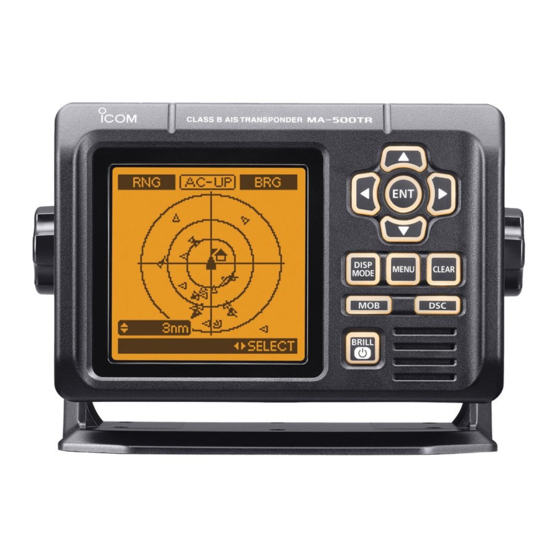
- Page 1 INSTRUCTION MANUAL CLASS B AIS TRANSPONDER MA-500TR This device complies with Part 15 of the FCC Rules. Operation is subject to the condition that this device does not cause harmful interference.
-
Page 2: Important
MA-500TR. We appreciate you making the MA-500TR your transpon- der of choice, and hope you agree with Icom’s philosophy of “technology first.” Many hours of research and development EXPLICIT DEFINITIONS went into the design of your MA-500TR. -
Page 3: Fcc Information
(M5) Screws (5×20) Spring washers (M5) MXG-5000 is included with MA-500TR. gps receiver MXG-5000 (Referred to as Internal GPS) Cable length: Approx. 10 m (32.8 ft) • An instruction sheet comes with the MXG- 5000. -
Page 4: Radio Operator Warning
RADIO OPERATOR WARNING Icom requires the radio operator to meet the FAILURE TO OBSERVE THESE LIMITS MAY ALLOW FCC Requirements for Radio Frequency Expo- THOSE WITHIN THE MPE RADIUS TO EXPERIENCE RF sure. An omnidirectional antenna with gain not RADIATION ABSORPTION WHICH EXCEEDS THE FCC greater than 9 dBi must be mounted a minimum MAXIMUM PERMISSIBLE EXPOSURE (MPE) LIMIT. -
Page 5: Installation Note
It is recommended that antenna of a maximum gain of 3 dB are used. If higher gain antenna are required then please contact your Icom distributor for revised installation recom- mendations. Operation: The exposure to RF electromagnetic field is only applicable when this device is transmitting. -
Page 6: Country Code List
COUNTRY CODE LIST • ISO 3166-1 Country Codes Country Codes Austria Liechtenstein Belgium Lithuania Bulgaria Luxembourg Croatia Malta Netherlands Czech Republic Norway Cyprus Denmark Poland Estonia Portugal Romania Finland Slovakia France Slovenia Germany Spain Greece Sweden Hungary Switzerland Iceland Turkey Ireland United Kingdom Italy... -
Page 7: Precautions
DO NOT Icom, Icom Inc. and the Icom logo are registered trademarks of Icom Incor- use harsh solvents such as benzine or alcohol porated (Japan) in Japan, the United States, the United Kingdom, Germany, when cleaning, as they will damage the transponder surfaces. -
Page 8: Table Of Contents
TABLE OF CONTENTS 5 OTHER FUNCTIONS ..........25–29 FOREWORD ................. i IMPORTANT ................. i ■ Message ..............25 EXPLICIT DEFINITIONS ............i ■ Waypoint ..............26 FCC INFORMATION ............ii ■ Lost target ..............29 SUPPLIED ACCESSORIES ..........ii 6 MENU MODE OPERATION ........30–36 RADIO OPERATOR WARNING .......... -
Page 9: Overview
OVERVIEW D ABOUT AIS D AIS Classes AIS is an acronym for “Automatic Identification System.” There are seven types of AIS stations; vessels, base stations, An AIS transponder is a short range data radio unit, used Aids to Navigation (AtoN), Search and Rescue (SAR), Search primarily for collision-risk management and navigation safety. -
Page 10: Panel Description
PANEL DESCRIPTION ■ Front panel q DISPLAY MODE KEY [DISP MODE] Function display (p. 4) <Common> ➥ Push to switch the display mode between the plotter, target list and danger list. (pp. 4−6) ➥ While in the Menu mode, push to exit it, and return to the plotter, target list or danger list display which was selected before you entered the Menu mode. - Page 11 PANEL DESCRIPTION e UP AND DOWN KEYS [∫]/[√] y CLEAR KEY [CLEAR] <Common> <Common> ➥ While in the Menu mode, push to select a menu item. ➥ Push to cancel the entered function, or return to the pre- (pp. 9, 30) vious screen.
-
Page 12: Function Display
PANEL DESCRIPTION ■ Function display q DISPLAY TYPE There are three display types; plotter, target list and danger list, and you can select your desired type using the [DISP MODE] key. Shows the selected display type. • When “N-UP” is displayed, the top of the plotter display repre- NOTE: When one of the following messages is displayed on sents North. -
Page 13: Panel Description 2
PANEL DESCRIPTION t TARGET BOX • Description of the icons Shows the selected AIS target (or waypoint, if it is set; see Icon Description pages 26–28 for setting detail). AIS target: Vessel • When a target box appears, push [ENT] to display the detail The tip of the target triangle automatically points screen of the selected AIS target or waypoint. - Page 14 PANEL DESCRIPTION ■ Function display (Continued) D Danger list display D Target list display In the plotter display, push [DISP MODE] to switch to the tar- In the target list display, push [DISP MODE] to switch to the get list display, which shows all AIS targets being detected by danger list display, which helps you to find any dangerous target whose CPA is within 6 nm (nautical miles) and TCPA is the transponder.
-
Page 15: Preparation
PREPARATION ■ MMSI code setting The 9-digit MMSI (Maritime Mobile Service Identity: DSC self ID) code can be set at power ON. If the MMSI code has al- ready been set, the following steps are not needed. Go to page 9. This initial code setting can be performed only once. - Page 16 PREPARATION ■ MMSI code setting (Continued) r Push [ENT] to enter the MMSI code setting mode. y After inputting the 9-digit code, push [ENT]. t Push [∫] or [√] to input the specific 9-digit MMSI code. • The MMSI confirmation screen appears. •...
-
Page 17: Initial Setting Mode
PREPARATION ■ Initial setting mode D MMSI code The Initial setting mode allows you to set the vessel’s infor- mation that is exchanged among the vessels and/or base Enter the vessel’s MMSI code. See page 7 for setting details. stations. And, you can set the seldom-changed NMEA Input/ Output settings. - Page 18 PREPARATION ■ Initial setting mode (Continued) DType of Ship D Internal/External GPS Antenna Position Select your vessel type. Set these measurements to indicate the internal and/or exter- nal GPS antenna position on the vessel. ➥ Push [∫] or [√] to select your vessel type from the list, •...
- Page 19 38400 bps. NMEA2 is used for communication between • “GPS Input1” is for the NMEA1, “GPS Input2” is for the NMEA2 the transponder and the Icom MarineCommander™ sys- and “GPS Input3” is for the NMEA3 ports setting. tem or a GPS receiver.
- Page 20 The Remote ID is included in the sentence of the format for This function should normally be set to “AIS.” the Icom own NMEA. q Push [∫] or [√] to select “AIS Output.” w Push [ENT] to select either “AIS” or “AIS+GPS.”...
- Page 21 PREPARATION D Name and Call Sign settings q Push [∫] or [√] to select the “Set Name” or “Set Call Sign” e Repeat step w to input all characters. that you want to program, then push [ENT] to enter the set- r Push [∫], [√], [Ω] or [≈] to select “FINISH,”...
-
Page 22: Basic Operation
BASIC OPERATION ■ Turning power ON IMPORTANT: BE SURE to connect the GPS receiver to e After the opening test is completed, the MMSI code ap- the transponder before turning the power ON. (p. 37) pears, if the code has already been set. •... -
Page 23: Display Backlight And Contrast Settings
BASIC OPERATION ■ Display backlight and ■ Plotter display operation contrast settings When the plotter display is selected, the display range and the icons of the AIS targets appear. You can change the display range You can adjust the display backlight and contrast settings. and type (North up or COG up) to suit your operating style. -
Page 24: Target List Display Operation
BASIC OPERATION ■ Target list display operation ■ Plotter display operation (Continued) D Setting the display type (North up/COG up) Select the display type between “North up” and “COG up.” he target list display shows all AIS targets being detected by the transponder, including their range and bearing infor- q Push [MENU] to enter the Menu mode. -
Page 25: Danger List Display Operation
BASIC OPERATION ■ Danger list display operation ■ About the detail screen The danger list display shows any dangerous target whose The detail screen shows information about the selected AIS CPA (Closest Point of Approach) distance is less than 6 nm target. - Page 26 BASIC OPERATION ■ About the detail screen (Continued) D Class A vessels’ DETAIL screens • AIS Class • CPA • Heading • MMSI Code • TCPA • Position Accuracy • Ship Name • Latitude (H: High, L: Low) • Country Name •...
- Page 27 BASIC OPERATION D Class B vessels’ DETAIL screens • AIS Class • Vendor ID • Heading • MMSI Code • CPA • TCPA • Position Accuracy • Ship Name • Latitude • Longitude (H: High, L: Low) • Country Name •...
- Page 28 BASIC OPERATION ■ About the detail screen (Continued) D AtoN targets’ DETAIL screens D Base Station targets’ DETAIL screens • AIS Class • Position Accuracy • CPA • TCPA • MMSI Code (H: High, L: Low) • Latitude • Longitude •...
- Page 29 BASIC OPERATION D AIS-SART targets’ DETAIL screens • Closest Point of Approach • Heading • Time to CPA • Position Accuracy • Type of AIS Target • Latitude • Longitude (H: High, L: Low) • MMSI Code • Speed Over Ground •...
- Page 30 BASIC OPERATION ■ About the detail screen (Continued) D MOB targets’ DETAIL screens • Closest Point of Approach • Heading • Time to CPA • Position Accuracy • Type of AIS Target • Latitude • Longitude (H: High, L: Low) •...
- Page 31 BASIC OPERATION D EPIRB-AIS targets’ DETAIL screens • Closest Point of Approach • Heading • Time to CPA • Position Accuracy • Type of AIS Target • Latitude • Longitude (H: High, L: Low) • MMSI Code • Speed Over Ground •...
-
Page 32: Individual Dsc Call (Possible Only When A Transceiver Is Connected)
BASIC OPERATION ■ Individual DSC call (Possible only when a transceiver is connected) When a transceiver* is connected to the transponder, you can [∫] transmit an Individual DSC call without needing to enter the vessel’s MMSI code, by simply selecting it’s AIS target and [√] the voice channel you wish to use on the transponder. -
Page 33: Other Functions
OTHER FUNCTIONS ■ Message D Receiving a message D Message logs A safety-related message of up to 161 characters can be re- The transponder automatically stores the last 20 received messages in the log memory. ceived from an AIS equipped vessel in the area. When a message is received, a beep sounds three times, The oldest message is automatically deleted when a new message is received. -
Page 34: Waypoint
OTHER FUNCTIONS ■ Waypoint D Display a waypoint list D Add a waypoint Up to 100 waypoints can be stored in the waypoint list. The position information that you want to memorize can be added as a waypoint. q Push [MENU] to enter the Menu mode. q Push [MENU] to enter the Menu mode. - Page 35 OTHER FUNCTIONS i Push [∫] or [√] to select “LAT:,” then push [ENT]. [∫], [√], o Push [∫], [√], [Ω] or [≈] to set the desired latitude data in [Ω], [≈] the table, then push [ENT] to input it. [ENT] ,”...
- Page 36 OTHER FUNCTIONS ■ Waypoint (Continued) D Edit a waypoint u Enter a waypoint name, latitude data and longitude data, A waypoint’s name, latitude and longitude data can be ed- ited. as described in steps t to !3 of “D Add a Waypoint” on pages 26 and 27.
-
Page 37: Delete A Waypoint
OTHER FUNCTIONS ■ Lost target D Delete a waypoint A waypoint can be deleted from the waypoint list. A vessel is regarded as a “Lost target” after a specified period of time has passed since the vessel last transmitted data, as q Push [MENU] to enter the Menu mode. -
Page 38: Menu Mode Operation
MENU MODE OPERATION ■ General ■ Menu mode items q Push [MENU] to enter the Menu mode. The Menu mode contains the following items. w Push [∫] or [√] to select the desired item, then push [ENT]. Item Ref. Item Ref. - Page 39 MENU MODE OPERATION D CPA/TCPA • Alarm • Slow Warn The GPS receiver calculated COG data of a vessel that is at You can turn the collision alarm function ON or OFF. anchor or drifting is unreliable, and therefore the CPA and TCPA data may not be calculated correctly.
- Page 40 MENU MODE OPERATION ■ Menu mode items D CPA/TCPA (Continued) D Own Static This screen shows your static vessel information such as • CPA, TCPA MMSI code, Vessel Name, Call Sign, Internal/External GPS Enter CPA (Closest Point of Approach) and TCPA (Time to antenna position and Type of Ship.
- Page 41 MENU MODE OPERATION D GPS Information D Own Dynamic The GPS Information screen shows the viewable GPS satel- This screen shows your dynamic vessel information such as lite’s information, when the internal or external* GPS receiver Latitude and Longitude data, SOG, COG, GPS receiver type, is connected.
- Page 42 MENU MODE OPERATION ■ Menu mode items (Continued) D Alarm Status D User Setting The Alarm Status screen shows the type, date and time of the The User setting mode allows you to set the seldom-changed last 25 malfunctions that were detected. settings, and you can “customize”...
- Page 43 MENU MODE OPERATION • Alarm Buzzer • Internal GPS The Internal GPS setting mode allows you to set the internal Turn the alarm buzzer function ON or OFF. GPS setting. ➥ Push [ENT] to toggle this function ON or OFF.* q Push [MENU] to enter the Menu mode.
- Page 44 MENU MODE OPERATION ■ Menu mode items D Channel information D User Setting (Continued) The channel information screen shows the channels 2087 <SETTING ITEMS> and 2088 information in which safety-related messages are transmitted to, and received from, the AIS targets. - SBAS (Satellite Based Augmentation System) Function The channel to be used is automatically set according to the The SBAS transmits signals to correct errors and improve...
-
Page 45: Installation And Connections
Connects the supplied DC power cable between this con- nector and a 12 V power source. vessel’s magnetic navigation compass. r HIGH-DENSITY D-SUB 15 PIN (NMEA IN/OUT) Connects an Icom MarineCommander™ system, naviga- tion equipment, external GPS receiver, etc. using the sup- plied OPC-2014 nmea connector cable See page 39 for the pin assignment. - Page 46 INSTALLATION AND CONNECTIONS ■ Connections (Continued) t GROUND TERMINAL D High-density D-sub 15 pin assignment Connects to a vessel ground to prevent electrical shocks t r e w and interference from other equipment occurring. Use a !0 o i u Rear panel view self-tapping screw (3 ×...
- Page 47 — ALERT2 target is closer than your CPA and TCPA settings. VDM, VDO, ALR, ACA, ACS, TXT, Connects to the Icom MarineCommander™ sys- NMEA2 OUT (–) RMC*, GGA*, GNS*, GLL*, VTG*, tem or to a GPS receiver. Same as pins 2 and 3...
-
Page 48: Fuse Replacement
INSTALLATION AND CONNECTIONS ■ Fuse replacement ■ About the VHF antenna One fuse is installed in the DC power cable. If the fuse blows, A key element in the performance of any communication sys- track down the source of the problem, have it repaired, and tem is the antenna. -
Page 49: Transceiver Connection
INSTALLATION AND CONNECTIONS ■ Transceiver connection • Antenna connector Connect the transponder and a transceiver using the The antenna uses a PL-259 connector. OPC-2014 . After connecting, an In- nmea connector cable dividual DSC call can be made to the AIS target using the 30 mm q Slide the coupling ring transponder without entering the target’s MMSI code. - Page 50 INSTALLATION AND CONNECTIONS ■ Transceiver connection (Continued) D IC-M603/M604 D IC-M504/M505 NMEA IN LEAD (Red) GPS receiver/External speaker connector NMEA OUT LEAD (White) Transceiver’s rear panel • GPS receiver/External speaker connector Transceiver’s rear panel r NMEAOUT (+) SP (+) e NMEAOUT (–) SP (–) •...
-
Page 51: Mounting The Transponder
INSTALLATION AND CONNECTIONS ■ Mounting the transponder D Using the mounting bracket • OVERHEAD MOUNTING The universal mounting bracket supplied with your transpon- der allows overhead or dashboard mounting. q Mount the bracket securely with the 4 supplied screws (5 × 20 mm) to a surface which is more than 10 mm ( ⁄... -
Page 52: Installation
INSTALLATION AND CONNECTIONS ■ MB-75 installation An optional MB-75 is available for mount- flush mount kit ing the transponder to a flat surface, such as an instrument panel. Bolt KEEP the transponder at least 1 m (3.3 ft) away from your vessel’s magnetic navigation compass. -
Page 53: Maintenance
If you are unable to locate the cause of a problem or solve The following chart is designed to help you correct problems which are not equipment malfunctions. it through the use of this chart, contact your nearest Icom Dealer or Service Center. PROBLEM... -
Page 54: Error Message
MAINTENANCE ■ Error message ■ Diagnostics Error message is displayed when a malfunction occurs that There are two types of diagnostic tests performed — Monitor has an error message programmed for it. test, Transponder test and Version information. Message contents Description •... - Page 55 MAINTENANCE • Transponder Test • Version Information You can check whether the transponder units work properly. You can check the version information of SW (Software), FI (Function Image) and the Internal GPS receiver. q Push [MENU] to enter the Menu mode. w Push [∫] or [√] to select “Diagnostics,”...
-
Page 56: Specifications And Option
SPECIFICATIONS AND OPTION ■ Specifications D Dimensions D General 145 (5.71) • Frequency coverage : 161.975, 162.025 MHz (default) 156.025–162.025 MHz • Type of emission : 16K0GXW (GMSK) • Current drain (at 12 V nominal) : TX: 1.5 A, RX: 0.7 A •... -
Page 57: Template
TEMPLATE 165 (6 ⁄ 146 (5 ⁄ R12 (Max.) Unit: mm (inch) -
Page 59: Aton Code And Description
AtoN CODE AND DESCRIPTION The following table shows all the AtoN codes which appear on the detail screens of an “AtoN.” (p. 20) Code Code Description Description DEFAULT, TYPE OF ATON NOT SPECIFIED BEACON, PREFERRED CHANNEL STARBOARD HAND REFERENCE POINT BEACON, ISOLATED DANGER RACON BEACON, SAFE WATER... - Page 60 < Intended Country of Use > A-6860D-1EX-e Printed in Japan 2011–2013 Icom Inc. © 1-1-32 Kamiminami, Hirano-ku, Osaka 547-0003, Japan Printed on recycled paper with soy ink.