Table of Contents
Advertisement
Operating Instructions/Bedienungsanleitung/
Unità per il comando a distanza/Unidad de control remote/
Before operating this product, please read the instructions carefully and save this
manual for future use.
Bitte lesen Sie vor Inbetriebnahme dieses Produkts die Anleitungen sorgfältig durch
und bewahren Sie dieses Handbuch für spätere Verwendung auf.
Avant de vous servir de ce produit, veuillez lire attentivement les instructions et
enregistrer ce manuel pour une utilisation ultérieure.
Prima di utilizzare questo prodotto, leggere attentamente le istruzioni di questo
manuale e conservarlo per riferimento futuro.
Antes de poner este producto en funcionamiento, lea atentamente las instrucciones
y conserve este manual para uso futuro.
使用本产品前,请仔细阅读本说明书,并妥善保存以备日后参考。
お買い上げいただき、まことにありがとうございました。
この取扱説明書をよくお読みの上、正しくお使いください。
特に「安全上のご注意」は、ご使用前に必ずお読みいただき、安全にお使いください。
お読みになったあとは、保証書と一緒に大切に保管し、必要なときにお読みください。
F0706T0 -F @
Printed in Japan
Mode d'emploi/Istruzioni per l'uso/
Instrucciones de funcionamiento/
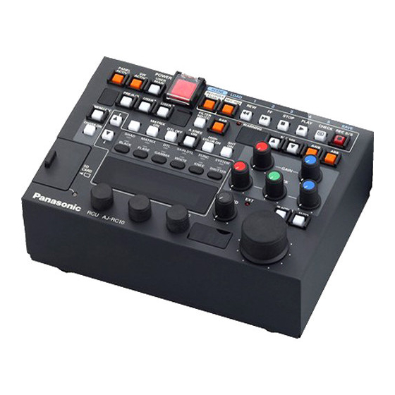
Remote Control Unit/Fernsteuereinheit/
摄像机遥控器 / リモートコントロールユニット
操作手册 / 取扱説明書
Module de télécommande/
AJ-
Model No.
G
中
文
日
本
語
VQT1A65
Advertisement
Table of Contents

Related Manuals for Panasonic AJ-RC10G


Summary of Contents for Panasonic AJ-RC10G
- Page 1 Operating Instructions/Bedienungsanleitung/ Mode d’emploi/Istruzioni per l’uso/ Unità per il comando a distanza/Unidad de control remote/ Before operating this product, please read the instructions carefully and save this manual for future use. Bitte lesen Sie vor Inbetriebnahme dieses Produkts die Anleitungen sorgfältig durch und bewahren Sie dieses Handbuch für spätere Verwendung auf.
-
Page 2: Read This First
Read this first! For General DO NOT REMOVE PANEL COVERS BY UNSCREWING THEM. To reduce the risk of electric shock, do remove serviceable parts inside. Refer servicing to qualified service personnel. WARNING: TO REDUCE THE RISK OF FIRE OR SHOCK HAZARD, DO NOT EXPOSE THIS EQUIPMENT MOISTURE. - Page 3 Read this first! (Continued) For USA CAUTION RISK OF ELECTRIC SHOCK DO NOT OPEN CAUTION: TO REDUCE THE RISK OF ELECTRIC SHOCK, DO NOT REMOVE COVER (OR BACK). NO USER SERVICEABLE PARTS INSIDE. REFER TO SERVICING TO QUALIFIED SERVICE PERSONNEL. The lightning flash with arrowhead symbol, within...
-
Page 4: Table Of Contents
Table of Contents Read this first! ... 1 General ... 4 Features ... 4 Accessories ... 4 Connection... 5 System configuration... 5 Parts and functions... 6 Front panel ...6 Rear panel ...15 Basic operations ... 16 When the power is on...16 To enable the buttons/volumes ...16 To disable buttons/volumes...16 Operation of the camera recorder ...17... -
Page 5: General
General The AJ-RC10G (hereinafter called “the unit”) is a remote control unit connected to the camera recorder. The unit controls the camera recorder from the controller and is capable of changing numerical values in the menu. Coverage can be extended by 50m by using the dedicated cable. -
Page 6: Connection
When the camera recorder is used while it is being moved, the cable must be fixed to the tripod or the handle of the camera recorder so that no force is applied directly to the connector. Camera recorder Dedicated 10-pin cable AJ-RC10G Monitor Video cable VIDEO OUT connector... -
Page 7: Parts And Functions
Parts and functions Front panel Panel part !2" !3" !1" !1" POWER button ON/OFF switch of the main power supply of the main unit !2" PANEL ACTIVE button For controlling which panel operations are available When the lamp is on: The panel operations are available. - Page 8 Parts and functions Camera recorder/Scene file operation !1" !2" !3" !4" !5" !9" !1" RECORDER ENABLE button For switching between the recorder mode and the scene file mode When the lamp is on: Recorder mode Buttons from !3" to !8" are operated as control buttons for the recording.
- Page 9 Parts and functions !7" CHECK/5-button In recorder mode: This is the recording confirmation button. If the button is pressed when recording is paused, the recording can be checked. The lamp flashes when the tape is rewound and is turned on when the tape is replayed. In scene file mode: 5 is selected as the number for the scene file to be saved or loaded.
- Page 10 Parts and functions Basic camera operations !1" !5" !4" !2" !3" !1" USER MAIN button This button has the same function as the USER MAIN switch on the camera recorder. The lamp is on only when the button is pressed. <Note>...
- Page 11 Parts and functions Basic camera operations (Continued) !9" !10" !11" !12" !13" !9" GAIN display This displays the image gain of the camera recorder. The initial value is the gain value at the time when the GAIN switch on the camera recorder was set to “L”.
- Page 12 Parts and functions Basic camera operations (Continued) !14" !15" !16" !17" !18" !14" MATRIX ON button This button switches the matrix function ON/ OFF. Even if the MATRIX is set to “OFF” in the menu of the camera recorder, it switches to “ON”...
- Page 13 Parts and functions Volume settings !2" !3" !4" !11" !7" !8" !1" VR ACTIVE button This is a button to approve/inhibit operations of the GAIN volumes from !2" to !3" and the BLACK volumes from !4" to !6". When the power of the unit is on, it inhibits operations.
- Page 14 Parts and functions Menu operation of the unit !3" !9" !12" !6" !10" !4" !7" !20" !21" !5" !8" !1" !2" !1" LCD panel This displays the menus for items selected with the menu operation buttons !2", !5", !8", !11", !14" and !17". This is also capable of displaying the time code.
- Page 15 Parts and functions !14" KNEE/FUNC button This selects the large item displayed on the LCD panel. The display will switch to KNEE # FUNC # before entering the menu mode # KNEE step by step every time the button is pressed. !15"...
-
Page 16: Rear Panel
Parts and functions Rear panel !2" !1" !6" VIDEO OUT CAM RCU CABLE FREQUENCY LEVEL !3" !5" !4" !1" Camera connection connector To connect the 10-pin camera control cable. Pin No. 9 10 !2" VIDEO OUT connector An NTSC or PAL monitor is connected for operating the menu on the main unit of the camera recorder. -
Page 17: Basic Operations
Basic operations When the power is on When the POWER button is pressed, the lamp for the PANEL ACTIVE button is on, and the settings of the camera recorder are read into the unit. The respective numerical values are displayed on the PRE/A/B display, CC/ND display, GAIN display, and the IRIS display, while R GAIN and B GAIN are displayed on the LCD panel. -
Page 18: Operation Of The Camera Recorder
Basic operations Operation of the camera recorder 1) Operation of the display interlocking switch Select the white balance settings by using the PRE/A/B button and monitoring the PRE/A/B display. The state of the camera recorder filter is displayed on the CC/ND display. If two filters are installed on the camera recorder, it is impossible to switch the filters from the unit but it is possible to switch the... -
Page 19: Operation Of The Camera Using The Unit Volume
Basic operation (Continued) Operation of the camera using the unit volume When the lamp of the PANEL ACTIVE button is on, operations of the M.PED volume and the IRIS volume are enabled. When the lamp of the AUTO IRIS button is on, the IRIS volume functions as the volume for setting the target value of the auto iris. -
Page 20: Operation Of The Scene File
Basic operation 3) M.PED volume When the volume operation is enabled, the unit operates in the absolute value mode where the value is fixed in accordance with the position of the volume. The value will be “0” by clicking the center. The variable amount is within a range between the minimum value of –200 and the maximum value of +200 with the center value... -
Page 21: Operation For Recording
Basic operation (Continued) <Notes> If a scene file is loaded while the volume operation mode is set to the absolute value mode, and then the VR ACTIVE button is operated, the set value will correspond to the volume angle and the loaded value will be lost. -
Page 22: Saving/Loading Of Scene Files Onto The Sd Memory Card
Saving/Loading of scene files onto the SD memory card It is possible to store up to 8 sets of settings for the unit. While data on the card are read or written, any operation of the unit panel is inhibited. Insert the SD memory card into the SD memory card slot on the unit and operate the unit menu. -
Page 23: To Write Data On The Card
Saving/Loading of scene files onto the SD memory card To write data on the card Select “SYSTEM” using the SHUTTER/ SYSTEM button, and display the menu on the second layer using the 4button. When the indication “CARD-WR” is displayed on the LCD panel together with the file number displayed under the indication, turn the Rotary Encoder 1 to select the file. -
Page 24: Menu Operation
Menu operation Operations using the LCD panel The menu can be adjusted using the Rotary Encoders (1 to 3) after displaying the menu on the LCD panel. Press one of the following buttons: BLACK/ SHAD button, FLARE/MATRIX button, GAMMA/DTL button, WHITE/SKINDTL button, or KNEE/FUNC button to select an item on the menu. -
Page 25: Menu Item
Menu item Menu The menu items on the unit may vary with the camera recorder connected to the unit. For the following menu items, the factory settings for the unit only are set separately from the camera recorder. BLACK-VR-CONTROL, BLACK-VR- MODE, and BLACK-VR-RANGE in “BLACK”... -
Page 26: Flare
Menu item (Continued) FLARE Variable Layer Item Contents description Storage range RFLAR –100 To set the flare for Rch +100 GFLAR –100 To set the flare for Gch +100 BFLAR –100 To set the flare for Bch +100 FLAR- To set ON/OFF of the CORRECT flare correction <Note>... - Page 27 Menu item (Continued) WHITE (Continued) Variable Layer Item Contents description Storage range COLR- 2300k To set the color TEMP-PRE temperature in the AWB 8000k AWB-A To set the position of the WHITE BAL switch and the assignment of MEM: This assigns the memory value when the AWB is executed.
-
Page 28: Knee
Menu item (Continued) KNEE Variable Layer Item Contents description Storage range M-KNEE To set the mode when the AUTO KNEE switch is off MANUAL KNEE OFF: KNEE OFF MKNPNT 70.0% To set the position of the MANUAL KNEE 107.0% POINT by 0.5% step MKNSLP To set the tilt angle of the MANUAL KNEE... -
Page 29: Shad
Menu item (Continued) SHAD Variable Layer Item Contents description Storage range B-SHD To select the black shading ON/OFF DETECT EXEC To activate the auto black shading adjustment W-SHD To select the white shading ON/OFF HSAW –255 To adjust the R-H-SAW (W-R) white shading +255... -
Page 30: Dtl
Menu item (Continued) Variable Layer Item Contents description Storage range MDTL –31 To set the level of the master detail (H and V) HDTL To set the H.DTL LEVEL VDTL To set the V.DTL LEVEL CORG To set detailed noise elimination level FREQ To set the H.DTL FREQ... -
Page 31: Func
Menu item (Continued) SKIN DTL (Continued) Variable Layer Item Contents description Storage range ICENT To set the center position on the I-axis (to set the area where SKIN TONE is effective) IWIDTH To set the width of the area where SKIN TONE on the I-axis with the center position at I CENT is effective... -
Page 32: System
Menu item (Continued) FUNC (Continued) Variable Layer Item Contents description Storage range BLK- –3 To set the gamma curve GAMMA –2 for dark portions –1 RC-DATA- To select whether the SAVE value adjusted in the unit will be retained in the main unit of the camera recorder or not, when the unit is... -
Page 33: Connection Cable
Connection cable A 10 m connection cable is attached to the unit. To extend the cable, use the optional dedicated cable. If several 10 m cables are connected in tandem, the power supply may be unstable due to voltage drops etc. In an emergency, apply a higher voltage within a range from 11 V to 17 V for the power supply of DC 12 V to the camera recorder. -
Page 34: Specifications
Specifications Power supply: DC 12 V Power consumption: 6 W indicates safety items. External dimensions (W a H a D) 185 mm a 131 mm a 60 mm (7-5/16 inches a 5-3/16 inches a 2-5/8 inches) Weight 1.3 kg (2.87 lb) Operating temperature 0 °C to +40 °C (32 °F to 104 °F) Storage temperature... - Page 35 Information on Disposal for Users of Waste Electrical & Electronic Equipment (private households) This symbol on the products and/or accompanying documents means that used electrical and electronic products should not be mixed with general household waste. For proper treatment, recovery and recycling, please take these products to designated collection points,where they will be accepted on a free of charge basis.
- Page 36 PANASONIC BROADCAST & TELEVISION SYSTEMS COMPANY UNIT COMPANY OF PANASONIC CORPORATION OF NORTH AMERICA Executive Office: One Panasonic Way 4E-7, Secaucus, NJ 07094 (201) 348-7000 EASTERN ZONE: One Panasonic Way 4E-7, Secaucus, NJ 07094 (201) 348-7196 Southeast Region: (201) 348-7162 WESTERN ZONE: 3330 Cahuenga Blvd W., Los Angeles, CA 90068 (323) 436-3500...