Table of Contents
Advertisement
Quick Links
NOTE:
Please read all instructions
carefully before using this
product
Table of Contents
Safety Notice
Hardware Identifier
Assembly Instruction
Parts List
Warranty
Ordering Parts
Model
TC-1800
Retain This
Manual for
Reference
07-01-09
OWNER'S
MANUAL
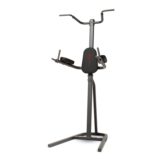
POWER STATION
14777 DON JULIAN RD., CITY OF INDUSTRY, CA 91746
Tel: (800) 999-8899 Fax: (626) 961-9966
www.impex-fitness.com
info@impex-fitness.com
APEX
TC-1800
®
IMPEX
INC.
Advertisement
Table of Contents

Related Manuals for Impex APEX TC-1800


Summary of Contents for Impex APEX TC-1800
- Page 1 NOTE: Please read all instructions carefully before using this product APEX Table of Contents POWER STATION Safety Notice Hardware Identifier TC-1800 Assembly Instruction Parts List Warranty Ordering Parts Model TC-1800 Retain This Manual for Reference 07-01-09 OWNER'S MANUAL ® IMPEX INC.
-
Page 2: Table Of Contents
ORDERING PARTS..................… 14 BEFORE YOU BEGIN ® Thank you for selecting the APEX TC-1800 by IMPEX INC. For your safety and benefit, read this manual carefully before using the machine. As a manufacturer, we are committed to provide you complete customer satisfaction. If you have any questions, or find there are missing or damaged parts, we guarantee you complete satisfaction through direct assistance from our factory. -
Page 3: Important Safety Notice
IMPORTANT SAFETY NOTICE PRECAUTIONS This exercise machine is built for optimum safety. However, certain precautions apply whenever you operate a piece of exercise equipment. Be sure to read the entire manual before you assemble or operate your machine. In particular, note the following safety precautions: 1. -
Page 4: Warning Label Placement
WARNING LABEL PLACEMENT The warning label shown here has been placed on the Stabilizer. If the labels are missing or illegible, please call customer service at 1-800-888-8899 for replacements. Apply the labels in the location shown. -
Page 5: Hardware Identifier
HARDWARE PACK NOTE: The following parts are not drawn to scale. Please use your own ruler to measure the size. -
Page 6: Assembly Instruction
ASSEMBLY INSTRUCTION Tools Required for Assembling the Machine: Two Adjustable Wrenches and Allen Wrenches NOTE: It is strongly recommended that two or more people assemble this machine to avoid possible injury. STEP 1 (See Diagram 1) A.) Do not tighten Nuts and Bolts until instructed to do so. B.) Connect the Left and Right Base Frame (#1 &... - Page 7 STEP-2 (See Diagram 2) A.) Attach the Lower Vertical Frame (#4) to the Stabilizer (#3). Secure it with two M10 x 2 ½” Allen Bolts (#24), four Ø ¾” Washers (#32), and two M10 Aircraft Nuts (#36). B.) Do not tighten the Nuts and Bolts yet. DIAGRAM 2...
- Page 8 STEP 3 (See Diagram 3) A.) Attach the Rear Support Frame (#5) to the joint of Left & Right Base Frame (#1 & #2). Secure them with M10 x 2 ½” Allen Bolts (#24), four Ø ¾” Washers (#32), and two M10 Aircraft Nuts (#36) from the side.
- Page 9 DIAGRAM 3...
- Page 10 STEP 4 (See Diagram 4) A.) Attach the Left Dip Support (#7) to Right Dip Support (#8) to the Upper Vertical Frame (#6) B.) Attach the holes on the bracket of Left and Right Dip Support to the holes on Upper Vertical Frame (#6) from each side.
- Page 11 STEP 5 (See Diagram 5) A.) Attach the Backrest Board (#15) to the Upper Vertical Frame (#6). Secure it with two M8 x 2 3/8” Allen Bolts (#30) and two Ø 5/8” Washers (#33). B.) Insert one Vertical Handle (#11) into the hole on Left Dip Support (#7). Secure it with one...
- Page 12 M10 x 1” Allen Bolt (#27) and one Ø ¾” Curved Washer (#34). Repeat same step to install the other Vertical Handle to Right Dip Support (#8). C.) Attach the Arm Pads to Left and Right Dip Support. Secure each Pad with two M8 x 2 ¾” Allen Bolts (#29) and two Ø...
-
Page 13: Exploded Diagram
EXPLODED DIAGRAM... -
Page 14: Parts List
Parts list KEY NO. DESCRIPTION Q’ty Left Base Frame Right Base Frame Stabilizer Lower Vertical Frame Rear Support Frame Upper Vertical Frame Left Dip Support Right Dip Support Left Chin-up Handle Right Chin-up Handle Vertical Handle 4 ¾” x 1 ¾” Bracket 5 ½”... -
Page 15: Limited Warranty
® IMPEX INC. LIMITED WARRANTY ® IMPEX Inc. ("IMPEX ") warrants this product to be free from defects in workmanship and material, under normal use and service conditions, for a period of two years on the Frame from the date of purchase. This warranty extends only to the original purchaser. IMPEX's obligation under this Warranty is limited to replacing or repairing, at IMPEX's option.