Table of Contents
Advertisement
Refrigeration
System Installation
H-IM-82B
July 2008
Part No. 25001901
Replaces H-IM-82A (6/06)
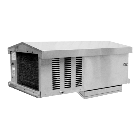
Refrigeration System
For Outdoor Applications
Table of Contents
1. Owner's Installation Instructions
Specifications ....................................................................................2
Dimensional Diagrams ..................................................................3
Space and Location Requirements
Recommended Unit Placement .................................................4
General Safety Information..........................................................5
Standard Installation Procedure ................................................6
Outdoor Unit Installation Instructions.....................................7
2. Freezers
Service Information
Sequence of Operation
Freezer System Pre-Setpoints
Programming Electric Defrost Controls ........................... 8-10
Installation and
3. Coolers
Defrost Controls
Sequence of Operation
Operation Guide
Maintenance .................................................................................. 11
System Troubleshooting Chart ................................................ 12
Replacement Parts ....................................................................... 13
5. Wiring Information
Electrical Wiring Diagrams ..................................................14-19
6. Warranty Information ....................................................... 20
© 2008 Heatcraft Refrigeration Products LLC
Advertisement
Table of Contents

Related Manuals for Heatcraft Refrigeration Products Refrigeration System H-IM-82B


Summary of Contents for Heatcraft Refrigeration Products Refrigeration System H-IM-82B
-
Page 1: Table Of Contents
Programming Electric Defrost Controls ... 8-10 Installation and 3. Coolers Defrost Controls Sequence of Operation Operation Guide Maintenance ... 11 4. Service Information System Troubleshooting Chart ... 12 Replacement Parts ... 13 5. Wiring Information Electrical Wiring Diagrams ...14-19 6. Warranty Information ... 20 © 2008 Heatcraft Refrigeration Products LLC... -
Page 2: Performance/Electrical Data
Performance / Electrical Data Table 1. COOLERS – Air Defrost Systems BTUH @ 95˚F Model 35˚F Box Temp 38˚F Box Temp PTT047H2B 4,980 PTT063H2B 6,680 PTT072H2B 7,630 PTT099H2B 10,490 11,340 PTT099H2C 10,490 11,340 PTT128H2B 13,570 14,520 PTT128H2C 13,570 14,520 Table 2. FREEZERS – Electric Defrost Systems BTUH @ 95˚F Model 0˚F -10˚F Box Temp Box Temp PTT021L6B 2,680 2,160 PTT031L6B 4,220 3,190 PTT044L6B 5,870 4,530 PTT052L6B 7,000 5,360... -
Page 3: Dimensional Diagrams
Dimensional Diagrams Medium Figure A. Cabinet Dimensions without weather hood Models PTT 021, 031, 044, 047, 063, 072 25" x 25" panel opening required for evaporator section of medium cabinet sizes. * 21.5" with weather hood. Large Figure B. Cabinet without weather hood Models PTT 052, 069, 099, 128 25" x 38 " panel opening required for evaporator section of large cabinet sizes. * 23.5" with weather hood. Medium Figure C. -
Page 4: Recommended Unit Placement
Recommended Unit Placement For PTT Models Some general rules for the evaporator section placement which must be followed are: Ensure that the structural integrity of the box can withstand the weight of the top mounted equipment. The air pattern must cover the entire room. NEVER locate the evaporator section over doors. Location of aisles, racks, etc. -
Page 5: Rigging
6. When unpacking the system, care should be taken to prevent damage. 7. Avoid removing the shipping base until the unit has been moved to the final destination. 8. Complete warranty return card for each unit and mail to Heatcraft Refrigeration Products. Table 4. Control Factory Default Settings Temperature Models Set Points Cooler Models 35˚F... -
Page 6: Standard Installation Procedure
The Outdoor comes standard with the following additional components: • Crankcase Heater • Drain Line Heater • Weather Hood • Fan Cycling (Pressure on 1 fan models, Pressure and Ambient on 2 fan models). Standard Installation Procedure PTT Models For outdoor use 1. Provide a 25" X 25" (medium cabinet) or 25" X 38.5" (large cabinet) opening in the roof of walk-in cooler or as specified by the panel manufacturer. -
Page 7: Outdoor Unit Installation Instructions
Example Outdoor Curb Installation This area of curb may be solid. Figure 1. Curb placed on roof of walk-in cooler. Figure 3. PTT unit placed on roof of walk-in color. (see rigging instructions). PTT Models (Curb supplied by others) Figure 2. Roof membrane placed over curb. Note: Do not caulk around the base of com- pressor compartment. -
Page 8: Maintenance
Medium and Large Cabinet Freezers Service Information units are designed for maximum durability, reliability and simplicity. comes to you ready for operation, fully charged and with all controls preset at the factory. The following information is provided as an aid in the event that service is required. Maintenance The evaporator section of a system should be checked at... - Page 9 MAIN FUNCTIONS HOW TO SEE THE SETPOINT 1. Push and immediately release the SET key: the display will show the Set point value. HOW TO CHANGE THE SETPOINT 1. Push the SET key for more than 2 seconds to change the Set point value; 2. The value of the set point will be displayed and the LED starts blinking;...
- Page 10 DISPLAY °C=Celsius; °F=Fahrenheit. WARNING: When the measurement unit is changed the SET Temperature point and the values of the parameters Hy, measurement unit LS, US, Ot, ALU and ALL have to be checked and modified if necessary DEFROST Defrost type EL = electrical heater;...
-
Page 11: Maintenance
All Cooler Models Cooler Defrost Control Cooler units utilize an electronic temperature control. The temperature may be adjusted by setting the dial. This control is preset to provide 3 hours of compressor run time between defrost cycles. Defrosts are temperature terminated and cannot be reprogrammed. The temperature control is programmed for minimum on cycle of one minute and minimum off cycle of four minutes. -
Page 12: System Troubleshooting Chart
Table 5. System Troubleshooting Chart PROBLEM POSSIBLE CAUSES Compressor 1. Main switch open. will not run 2. Fuse blown. 3. Thermal overloads tripped. 4. Defective contactor or coil. 5. System shut down by safety devices. 6. No cooling required. 7. Motor electrical trouble. 8. Loose wiring. Compressor 1. -
Page 13: Replacement Parts
Right source. Right parts. Right now. InterLink™ is your link to a complete line of dependable and certified commercial refrigeration parts, accessories and innovative electronic controls for all Heatcraft Refrigeration Products (HRP) equipment. At InterLink, we provide our wholesalers with a comprehensive selection of product solutions and innovative technologies for the installed customer base. -
Page 14: Electrical Wiring Diagrams
Medium and Large Cabinet Models Wiring. 208-230/1/60 voltages. Cooler - Air Defrost Systems - Single Phase Diagram 1. Wiring Diagram for System, Air Defrost 208-230/1/60 (B): Models PTT047H2B, PTT063H2B, PTT072H2B, PTT099H2B, and PTT128H2B. - Page 15 Medium and Large Cabinet Models Wiring. 208-230/1/60 voltages Indoor and Outdoor Models with Dixell XR-60C Controller Freezer - Electric Defrost Systems - Single Phase Diagram 2. Wiring Diagram for System, Electric Defrost 208-230/1/60 (B): Models PTT021L6B, PTT031L6B, PTT044L6B, PTT052L6B, and PTT069L6B.
- Page 16 Medium and Large Cabinet Models Wiring. 208-230/1/60 voltages Indoor and Outdoor Models with Paragon Controller Diagram 3. Wiring Diagram for System, Electric Defrost 208-230/1/60 (B): Models PTT021L6B, PTT031L6B, PTT044L6B, PTT052L6B and PTT069L6B.
- Page 17 Large Cabinet Models Wiring. 208-230/3/60 voltage. Cooler - Air Defrost Systems - Three Phase Diagram 4. Wiring Diagram for System, Air Defrost 208-230/3/60 (C): Models PTT099H2C and PTT128H2C.
- Page 18 Large Cabinet Models Wiring. 208-230/3/60 voltage Indoor and Outdoor Models with Dixell XR-60C Controller Freezer - Electric Defrost Systems - Three Phase Diagram 5. Wiring Diagram for System, Electric Defrost 208-230/3/60 (C): Models PTT052L6C and PTT069L6C only.
- Page 19 Large Cabinet Models Wiring. 208-230/3/60 voltage Indoor and Outdoor Models with Paragon Controller Freezer - Electric Defrost Systems - Three Phase Diagram 6. Wiring Diagram for System, Electric Defrost 208-230/3/60 (C): Models PTT052L6C and PTT069L6C only.
-
Page 20: Warranty Information
LLC's factory will, at Heatcraft Refrigeration Products LLC's option, be repaired or replaced and returned to Buyer via lowest common carrier, or Heatcraft Refrigeration Products LLC may at its option grant Buyer a credit for the purchase price of the defective article. Upon...