NETGEAR ProSafe WC7520 Reference Manual
20-ap wireless controller
Hide thumbs
Also See for ProSafe WC7520:
- Reference manual (196 pages) ,
- Datasheet (6 pages) ,
- Installation manual (2 pages)

Related Manuals for NETGEAR ProSafe WC7520


Summary of Contents for NETGEAR ProSafe WC7520
-
Page 1: Reference Manual
ProSafe 20-AP Wireless Controller WC7520 Reference Manual 350 East Plumeria Drive San Jose, CA 95134 September 2010 202-10686-01 v1.2... -
Page 2: Technical Support
NETGEAR, Inc. Technical Support Thank you for choosing NETGEAR. To register your product, get the latest product updates, or get support online, visit us at http://support.netgear.com. -
Page 3: Table Of Contents
Bottom Panel With Product Label ......10 WC7520 Wireless Controller System Components ....11 NETGEAR ProSafe Access Points: WNAP210 and WNDAP350 . - Page 4 ProSafe 20-AP Wireless Controller WC7520 Reference Manual Access Point Discovery ........42 Understanding the Discovery Results.
- Page 5 ProSafe 20-AP Wireless Controller WC7520 Reference Manual Small-Scale WLAN Networks ....... . . 82 Larger Deployments .
-
Page 6: Chapter 1 Introduction And Overview
Deploy the Wireless Controller. Key Features and Capabilities The ProSafe 20-AP Wireless Controller WC7520 is for medium-sized businesses, schools, and hospitals. In a stacked configuration and with the appropriate licenses, a wireless controller can support up to 150 access points (APs) with up to 1,500 users or more. The wireless controller supports the IEEE 802.11a/b/g protocols and is upgradable to support the... - Page 7 ProSafe 20-AP Wireless Controller WC7520 Reference Manual A maximum of three stacked wireless controllers allows for up to 150 APs in a single network Support of 1:1 redundancy Support of 802.11a, 802.11b, and 802.11g modes by default with the option to purchase a license (WC75NL) to support the 802.11n mode...
-
Page 8: Package Contents
WC7520 ProSafe Wireless Controller Installation Guide Resource CD • If any of the parts are incorrect, missing, or damaged, contact your NETGEAR dealer. Keep the carton, including the original packing materials, in case you need to return the product for repair. -
Page 9: Front Panel Ports And Leds
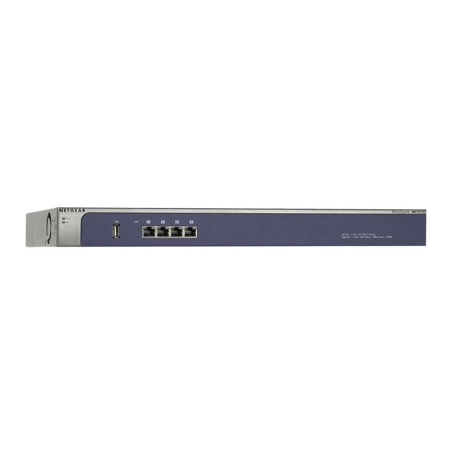
ProSafe 20-AP Wireless Controller WC7520 Reference Manual Front Panel Ports and LEDs The following figure shows the front panel ports and status LEDs of the wireless controller. Figure 1. From left to right, the wireless controller’s front panel shows the following ports and LEDs: Power LED. -
Page 10: Rear Panel Features
ProSafe 20-AP Wireless Controller WC7520 Reference Manual Table 1. Status Description The port is operating at 10 Mbps. Right LAN port LED On (amber) The port is operating at 100 Mbps. (one for each port) On (green) The port is operating at 1000 Mbps. -
Page 11: Netgear Prosafe Access Points: Wnap210 And Wndap350
For product documentation, see http://kb.netgear.com/app/products/model/a_id/12823. What Can You Do With the WC7520 Wireless Controller? These are some of the tasks that you can perform with a WC7520 wireless controller: Plan a Wireless Network Design a WLAN. Design an efficient WLAN with building and floor dimensions for your •... -
Page 12: Wc7520 Wireless Controller System Components
ProSafe 20-AP Wireless Controller WC7520 Reference Manual Estimate the number of required APs and their approximate locations. Estimate how • many APs you need for your wireless coverage and determine their optimum location for best coverage and performance. For more information, see Chapter 3, RF Planning. -
Page 13: Licenses
ProSafe 20-AP Wireless Controller WC7520 Reference Manual Manage MAC authentication. Specify trusted and untrusted MAC addresses for the • entire network. Manage rogue APs. Manage rogue APs and their associated clients in the network. • Manage guest access. Manage guest access and captive portal access to the network. -
Page 14: Maintenance And Support
For more information, see the License Configuration section in the datasheet at http://www.netgear.com/products/service-providers/access-points-wireless-controllers/wirele ss-management/WC7520.aspx. Maintenance and Support NETGEAR offers technical support seven days a week, 24 hours a day. Information about support is available on the NETGEAR ProSupport website at http://kb.netgear.com/app/answers/detail/a_id/212. Understanding the Web Management Interface Menu Layout The following figure shows the menu at the top and the left of the wireless controller’s Web... -
Page 15: Initial Connection And Configuration
Next. Advance to the next screen. Initial Connection and Configuration Follow the steps in this section to set up the wireless controller. For additional information, see the WC7520 ProSafe Wireless Controller Installation Guide at http://kb.netgear.com/app/products/model/a_id/13060. To set up, configure, and deploy the wireless controller: Connect the wireless controller to your computer: a. - Page 16 ProSafe 20-AP Wireless Controller WC7520 Reference Manual You must use a Web browser such as Microsoft Internet Explorer Note: 5.1 or later, Mozilla Firefox l.x or later with JavaScript, cookies, and SSL enabled. The wireless controller’s login window displays. Figure 5.
- Page 17 ProSafe 20-AP Wireless Controller WC7520 Reference Manual Configure the wireless controller and your network: a. RF Planning: Follow instructions in to plan the number and Chapter 3, RF Planning location of the APs. b. Configuring your network: Follow instructions in...
-
Page 18: Understanding Basic And Advanced Settings
ProSafe 20-AP Wireless Controller WC7520 Reference Manual One of the advanced features of the wireless controller is the capability to create multiple AP profile groups. Each access point operates using one profile group. The default profile group is called ‘basic.’ A profile group includes all the features that you can configure for an individual AP, including up to 8 SSIDs, security, QoS, load balancing and so on. -
Page 19: Deploy The Wireless Controller
ProSafe 20-AP Wireless Controller WC7520 Reference Manual The wireless controller is suitable for use in an office environment where it can be freestanding on its runner feet or mounted into a standard 19-inch equipment rack. Alternatively, you can rack-mount the wireless controller in a wiring closet or equipment room. - Page 20 ProSafe 20-AP Wireless Controller WC7520 Reference Manual 20 | Chapter 1: Introduction and Overview...
-
Page 21: Chapter 2 System Planning And Deployment Scenarios
These sections assume that you have deployed at least one wireless controller in your network and are ready to configure the wireless controller. For information about how to deploy the wireless controller in your network, see the WC7520 ProSafe Wireless Controller Installation Guide at http://kb.netgear.com/app/products/model/a_id/13060. - Page 22 ProSafe 20-AP Wireless Controller WC7520 Reference Manual VLANs Management VLAN The Management VLAN is the dedicated VLAN for access to the wireless controller. All traffic directed to the controller including HTTP, HTTPS, SNMP, SSH etc is carried with this VLAN TAG.
-
Page 23: Single Controller Configuration With Basic Profile Group
ProSafe 20-AP Wireless Controller WC7520 Reference Manual Client Authentication and Data Encryption A user must authenticate to the WLAN to be able to access WLAN resources. The wireless controller supports several types of security methods, including those that require an external RADIUS or LDAP authentication server. -
Page 24: Single Controller Configuration With Access Point Groups
ProSafe 20-AP Wireless Controller WC7520 Reference Manual Step Configuration Chapter/Section Reference If you have not yet done so, configure the system settings of Chapter 5, Configuring Network the wireless controller: Settings 1. Configure the country code of operation. Configuring General Settings page 52 2. -
Page 25: Stacked Controller Configuration
ProSafe 20-AP Wireless Controller WC7520 Reference Manual Step Configuration Chapter/Section Reference Configure up to 8 AP profile groups, and for each AP profile in a Chapter 8, Configuring Security group, do at least the following: and Wireless Security Profiles 1. Configure an SSID for wireless access. -
Page 26: Management Vlan And Data Vlan Strategies
ProSafe 20-AP Wireless Controller WC7520 Reference Manual Management VLAN and Data VLAN Strategies If your network includes 10 or more access points, NETGEAR recommends that you set up at least 2 VLAN groups, a management VLAN group, and a data VLAN group. If your network is large, you should create a number of data VLAN groups. -
Page 27: Deployment Scenarios
ProSafe 20-AP Wireless Controller WC7520 Reference Manual You should deploy the wireless controller on a trunk port on your switch. This port will have all types of traffic on it. Consider using one of the highest speed ports on your switch to ac como date the traffic load. - Page 28 ProSafe 20-AP Wireless Controller WC7520 Reference Manual Or do you like this style better? Figure 10. The APs and wireless controller are connected in the same subnet and use the same IP address range that is assigned for that subnet. There are no routers in between the APs and the wireless controller.
-
Page 29: Scenario Example 2: Advanced Network With Vlans And Ssids
ProSafe 20-AP Wireless Controller WC7520 Reference Manual Scenario Example 2: Advanced Network with VLANs and SSIDs This sample scenario consists of an advanced network with a wireless controller, PoE switch, layer 3 switch or router, APs, and several VLANs and SSIDs. These are the components in... - Page 30 ProSafe 20-AP Wireless Controller WC7520 Reference Manual Provisioning the Wireless Controller To provision the wireless controller in this network, perform the following tasks: For initial discovery and configuration of the APs, temporarily configure management VLAN 100 as an untagged management VLAN on both the wireless controller and the PoE switch.
-
Page 31: Scenario Example 3: Advanced Network With Redundancy
ProSafe 20-AP Wireless Controller WC7520 Reference Manual Scenario Example 3: Advanced Network With Redundancy This sample scenario consists of an advanced network with one wireless controller, one redundant wireless controller, one core switch, two PoE switches in different buildings, APs, and several VLANs and SSIDs. - Page 32 ProSafe 20-AP Wireless Controller WC7520 Reference Manual Figure 12. The APs and wireless controllers are connected in the same subnet and same VLAN and use the same IP address range that is assigned for that subnet. The core switch is located in between the wireless controllers and the PoE switches, to which the APs are connected.
- Page 33 ProSafe 20-AP Wireless Controller WC7520 Reference Manual Configure the IP address of wireless controller (see • Configuring IP and VLAN Settings on page 53). Verify that VLAN 1 is set as the management VLAN and is marked as untagged, •...
-
Page 34: Chapter 3 Rf Planning
RF Planning This chapter includes the following sections: on this page • RF Planning Overview on page 34 • Defining and Editing Buildings and Floors on page 37 • Planning Access Point Requirements on page 39 • Viewing and Managing Heat Maps for Deployed Plans on page 41 •... -
Page 35: Defining And Editing Buildings And Floors
ProSafe 20-AP Wireless Controller WC7520 Reference Manual Distance between floors • Total number of users and number of users per access point • Radio type or types • Desired data rates for access points • Identify areas where you do not necessarily want coverage •... - Page 36 ProSafe 20-AP Wireless Controller WC7520 Reference Manual Figure 13. The Buildings table shows the names of the previously defined buildings and their number of floors. To add a building, click Add. The Add Building popup window displays. Enter a name for your building in the Building Name field, and then click Add. The new building is added to the Buildings table.
- Page 37 ProSafe 20-AP Wireless Controller WC7520 Reference Manual Table 4. Building Name and Floors Setting Description Floors Floor Names The floor name is an alphanumeric string up to 64 characters in length. Floor Dimensions Enter the floor length in meters in the Length field; enter the floor width in meters in Width field.
-
Page 38: Planning Access Point Requirements
ProSafe 20-AP Wireless Controller WC7520 Reference Manual Planning Access Point Requirements After you have defined the buildings and floors, you need to specify the following RF requirements for each floor and each supported AP model (WNAP210 and WNDAP350): Frequency band. The radio frequency to be used (802.11b/bg/ng or 802.11a/na). - Page 39 ProSafe 20-AP Wireless Controller WC7520 Reference Manual Specify the WLAN requirements for the floor as explained in Table Table 5. Floor WLAN Requirements Setting Description Access Point Model Specify the AP model that you will use on the floor by selecting the WNDAP 350 or WNAP 210 radio button.
-
Page 40: Viewing And Managing Heat Maps For Deployed Plans
ProSafe 20-AP Wireless Controller WC7520 Reference Manual Move the APs to optimize coverage in desired areas and avoid coverage in unwanted areas based on the floor plan. Colored circles around the AP symbols indicate the expected approximate coverage of the individual AP, and the color of the circle represents the expected quality of the signal strength: a darker color indicates signal overlap with nearby APs. - Page 41 ProSafe 20-AP Wireless Controller WC7520 Reference Manual To view the heat map for a building floor and to adjust Access Points: Select Plans > Deployed. The Deployed Buildings screen displays. Figure 17. The Deployed Buildings screen shows a tab for each building that you previously defined.
-
Page 42: Rf Plan Example
ProSafe 20-AP Wireless Controller WC7520 Reference Manual The spectrum bar at the top of the screen indicates how the colors correspond to the signal strength and wireless coverage. To view information about an AP or client on the heat map, place your cursor over the icon. -
Page 43: Chapter 4 Access Point Discovery And Management
Rebooting Access Points Access Point Discovery You must run the Discovery Wizard for the wireless controller to discover supported NETGEAR access points on the LAN. See Appendix A, Access Point Firmware Compatibility for a list of compatible access points. The wireless controller can discover access points that are still in their factory default state and access points that are deployed and running. - Page 44 ProSafe 20-AP Wireless Controller WC7520 Reference Manual Using the Discovery Wizard The Discovery wizard finds access points that are not yet on the managed access point list. Select Access Point > Discovery Wizard. The Discovery Wizard screen displays. Figure 19. Discovery Wizard: Choose State of Access Points Select the radio button to specify the state of the access points that you want to discover: Factory default state: The access points have not been configured.
- Page 45 After you choose the network layout and specify the ranges (if prompted), when you click Next the following occurs: The wireless controller searches for NETGEAR products on the LAN based on MAC • address, and then identifies which products are supported access point models.
-
Page 46: Understanding The Discovery Results
The wireless controller located a NETGEAR access point that is not supported or located a NETGEAR device that is not an access point. If a new NETGEAR access point is not discovered, it might have a MAC address that the •... -
Page 47: Requirements For Auto Discovery
ProSafe 20-AP Wireless Controller WC7520 Reference Manual Requirements for Auto Discovery If the access points still have their factory default settings, the auto discovery process should work fine. If you changed the access point configuration, make sure that the access point configuration meets the following guidelines: All standalone access points have SNMP and SSH enabled. - Page 48 ProSafe 20-AP Wireless Controller WC7520 Reference Manual Figure 23. The managed AP list shows the following entries for each access point that you added to the list:. Table 6. Managed AP List Fields Field Description The IP address of the AP.
-
Page 49: Editing Access Point Information
ProSafe 20-AP Wireless Controller WC7520 Reference Manual Editing Access Point Information Select Access Point > Managed AP List to view the Managed AP List: Select the access point that you want to edit by selecting its radio button in the Edit column of the Managed AP List. - Page 50 ProSafe 20-AP Wireless Controller WC7520 Reference Manual Configure the settings as explained in 7. Some fields are masked out and cannot be Table edited. Table 7. Edit Access Point Settings Setting Description Access Point Info Name A unique value that the indicates the access point name. By default, the name is netgearxxxxxx, where xxxxxx represents the last six hexadecimal digits of APs MAC address.
-
Page 51: Rebooting Access Points
ProSafe 20-AP Wireless Controller WC7520 Reference Manual Rebooting Access Points Select Maintenance > Reboot/Reset > Access Points. The Reboot Access Points screen displays. Figure 25. As an optional step, enter the IP address, MAC address or name of an access point in the Search Access Point by IP/MAC/Name field, and click Search. -
Page 52: Chapter 5 Configuring Network Settings
Configuring Network Settings This chapter includes the following sections: on page 52 • Configuring General Settings on page 53 • Time Management on page 53 • Configuring IP and VLAN Settings on page 55 • Managing the DHCP Server on page 57 •... -
Page 53: Configuring General Settings
Field Description Name This unique value indicates the wireless controller name. NETGEAR recommends changing the name as soon as possible after setting up. The name must contain only alphabetical characters, numbers, and hyphens, and must be 31 characters or less. -
Page 54: Time Management
ProSafe 20-AP Wireless Controller WC7520 Reference Manual Time Management This screen lets you configure the time-related settings of your wireless controller and managed access points. To configure time settings: Select Configuration > System > Time. The Time Settings screen displays: Figure 27. - Page 55 ProSafe 20-AP Wireless Controller WC7520 Reference Manual To configure IP/VLAN settings: Select Configuration > System > IP/VLAN. The IP Settings screen displays: Figure 28. Configure the settings as explained in Table 10, IP Settings. Click Apply to save your settings.
-
Page 56: Management Vlans
ProSafe 20-AP Wireless Controller WC7520 Reference Manual Management VLANs Management VLANs are used for managing traffic (SNMP and HTTP) to and from the wireless controller and managed access points. Frames belonging to the management VLAN are not given any 802.1Q header when sent over the trunk. - Page 57 ProSafe 20-AP Wireless Controller WC7520 Reference Manual The wireless controller can function as a DHCP server. Multiple DHCP server pools can be added for different VLANs. This screen lets you enable and configure the DHCP server. You can also add DHCP servers.
-
Page 58: Managing Certificates
There is a default server certificate installed on the wireless controller, however this certificate does not guarantee security for production networks. NETGEAR strongly recommends that you replace the default server certificate on the wireless controller with a custom certificate issued for your site or domain by a trusted certificate authority (CA). -
Page 59: Configuring Syslog And Alarm Notification Settings
ProSafe 20-AP Wireless Controller WC7520 Reference Manual To add certificates: Select Configuration > System > Certificates. The Add Certificates screen displays: Figure 31. Configure the settings as explained in Table 12, Certificates Settings. Click Apply to save your settings. Table 12. Certificates Settings... -
Page 60: Configuring Alarm Notification Settings
ProSafe 20-AP Wireless Controller WC7520 Reference Manual To configure Syslog settings: Select Configuration > System > Alerts > Syslog. The Syslog Settings screen displays: Figure 32. Configure the settings as explained in Table 13, Syslog Settings. Click Apply to save your settings. -
Page 61: Configuring The Email Notification Server
ProSafe 20-AP Wireless Controller WC7520 Reference Manual To configure alarm actions: Select Configuration > System > Alerts > Alarms. The Alarm Actions screen displays: Figure 33. Specify which alarm severity should be included in the Syslog. Select Minor, Normal, Major, or Critical. - Page 62 ProSafe 20-AP Wireless Controller WC7520 Reference Manual Table 14. Email Configuration Field Description Server Address The server from which email notifications are sent. Port The port of the server from which email notifications are sent. Sender E-Mail Address The email address from which email notifications are sent.
-
Page 63: Chapter 6 Managing Access Point Groups
Managing Access Point Groups This chapter includes the following sections: on this page • Configuring Access Point Groups on page 63 • Managing Access Point Groups in the WLAN Not all networks need access point groups. Access point groups are useful if completely separate networks share a single LAN. -
Page 64: Managing Access Point Groups In The Wlan
ProSafe 20-AP Wireless Controller WC7520 Reference Manual This screen shows the existing groups by tab. Each group shows its name, radio mode, and authentication setting. Click the + button to add another group. To specify profile definition settings, select a group tab and click the Edit button. The Edit... - Page 65 ProSafe 20-AP Wireless Controller WC7520 Reference Manual To configure WLAN group assignments: Select Configuration > WLAN Network. The WLAN Group Assignment screen displays: Figure 37. The displayed settings are explained in on page 64. Table 15, WLAN Group Assignment To assign an access point to a group, select the correct group from the Group Name drop-down list.
-
Page 66: Chapter 7 Configuring Wireless Settings
When you are ready to configure your access points, NETGEAR recommends using the default settings as they are unless you have specific reasons to change them. -
Page 67: Basic Radio Configuration
ProSafe 20-AP Wireless Controller WC7520 Reference Manual Basic Radio Configuration To schedule the radio: Select Configuration > Wireless > Basic > Radio On/Off. The Schedule screen displays: Figure 38. Configure the settings as explained in Table 16, Schedule Radio On/Off. -
Page 68: Configuring Wireless Settings
ProSafe 20-AP Wireless Controller WC7520 Reference Manual To schedule the radio for access point groups: Select Configuration > Wireless > Advanced > Radio On/Off. The Schedule screen displays: Figure 39. Click a tab to select an access point group. Configure the settings as explained in Table 16, Schedule Radio On/Off. -
Page 69: Basic Wireless Configuration
ProSafe 20-AP Wireless Controller WC7520 Reference Manual Basic Wireless Configuration To configure basic wireless settings: Select Configuration > Wireless > Basic > Wireless. The Basic Wireless Settings screen displays: Figure 40. Configure the settings as explained in on page 68. -
Page 70: Advanced Wireless Configuration For Access Point Groups
The default is Auto. Advanced Wireless Configuration for Access Point Groups NETGEAR recommends using the default settings as they are to configure your access points unless you have specific reasons to change them. You can configure wireless settings for access points (see on page 67) or for access point groups. -
Page 71: Configuring Channels
ProSafe 20-AP Wireless Controller WC7520 Reference Manual To configure wireless settings for access point groups: Select Configuration > Wireless > Advanced > Wireless. The Advanced Wireless Settings screen displays: Figure 41. Click a tab to select the group that you want to configure. - Page 72 In order to adhere to best practices, when adjusting channel allocation, NETGEAR recommends the following: Select channels that do not overlap, for example, for 2.4 GHz use channels 1,6,11.
-
Page 73: Specifying Rf Management
ProSafe 20-AP Wireless Controller WC7520 Reference Manual Table 18. Channel Allocation Setting Description Automatic channel allocation You should leave this check box selected during normal operation. Automatic channel allocation distributes channels across the managed access points to reduce interference. Valid corporate channels •... -
Page 74: Basic Rf Management
ProSafe 20-AP Wireless Controller WC7520 Reference Manual referred to as channel width) to provide the best channel for the AP. For information about how to configure auto channel allocation, including the option to skip auto channel allocation if there is a heavy traffic load or voice activity, see Configuring Channels page 70. -
Page 75: Advanced Rf Management For Access Point Groups
ProSafe 20-AP Wireless Controller WC7520 Reference Manual Click Apply to save your settings. Table 19. RF Management Setting Description Maximum Neighbors to Participate The maximum number of neighboring access points that increase or in Self-healing decrease power to cover for a failing access point. Selecting 0 (zero) disables this feature. -
Page 76: Configuring Qos For Access Point Groups
ProSafe 20-AP Wireless Controller WC7520 Reference Manual To configure advanced RF management: Select Configuration > Wireless > Advanced > RF Management. The Advanced RF Management screen displays: Figure 44. Configure the settings as explained in Table 19, RF Management. Click Apply to save your settings. - Page 77 ProSafe 20-AP Wireless Controller WC7520 Reference Manual QoS prioritization and coordination of wireless medium access is on and QoS settings on the access point control downstream traffic, flowing from the access point to client station (AP EDCA parameters) and the upstream traffic flowing from the station to the access point (station EDCA parameters).
-
Page 78: Configuring Load Balancing
ProSafe 20-AP Wireless Controller WC7520 Reference Manual Table 20. QoS Settings Field Description AIFS (Arbitration Specifies a wait time (in milliseconds) for data frames. Valid values for AIFS are 1 Inter-Frame Space) through 255. CwMin (Minimum Upper limit (in milliseconds) of a range from which the initial random backoff wait time Contention Window) is determined. -
Page 79: Configuring Rate Limiting
ProSafe 20-AP Wireless Controller WC7520 Reference Manual is good in situations where the throughput expectation is high. In scenarios, where the clients can be expected to be far away or there are fewer access points, this should be set to a lower value. -
Page 80: Basic Rate Limiting
ProSafe 20-AP Wireless Controller WC7520 Reference Manual the specified percentage. The percentage configured for a BSSID is shared among all the clients connected to it. The total of the percentages distributed among the BSSIDs can be up to 100%. If a specific BSSID is to be left out of rate limiting, it could be configured to 0%, which effectively disables rate limiting for that BSSID. - Page 81 ProSafe 20-AP Wireless Controller WC7520 Reference Manual To configure the rate limit: Select Configuration > Profile > Advanced > Rate Limit. The Rate Limit screen displays: Figure 48. For each group, select its tab and specify the rate limit as a percentage.
-
Page 82: Chapter 8 Configuring Security And Wireless Security Profiles
Configuring Security and Wireless Security Profiles This chapter includes the following sections: on this page • Managing Wireless Security Profiles on page 87 • Managing Rogue Access Points on page 90 • Managing MAC Authentication and MAC Authentication Groups on page 93 •... -
Page 83: Small-Scale Wlan Networks
ProSafe 20-AP Wireless Controller WC7520 Reference Manual points. When the access points connect to the controller, the profile configurations are pushed onto the access points. When developing profiles, take the following into consideration: Configuration templates for authentication server settings in case of LDAP/RADIUS and •... -
Page 84: Configuring Basic Security Profiles
ProSafe 20-AP Wireless Controller WC7520 Reference Manual Configuring Basic Security Profiles This screen lets you edit up to eight security profiles per managed access point, depending on the number of profiles each access point supports. Separate profiles are applied to 802.11 b/bg/ng and 802.11a/na mode radios. - Page 85 ProSafe 20-AP Wireless Controller WC7520 Reference Manual on page 91. If the Configuring Basic MAC Authentication Settings selection in the Network Authentication field requires authentication, an additional field, the corresponding Authentication Server field displays. Use the tabs to select the wireless mode and the VLAN that you want to work with. Change...
-
Page 86: Configuring Advanced Security Profiles For Access Point Groups
ProSafe 20-AP Wireless Controller WC7520 Reference Manual Table 23. Network Authentication and Data Encryption (Continued) Network Data Encryption Description Authentication Legacy 802.1x • Select the WPA2 option only if all All require RADIUS configuration. clients support WPA2. If this option WPA with RADIUS is selected, you must use AES. - Page 87 ProSafe 20-AP Wireless Controller WC7520 Reference Manual To configure security profiles for a specific access point group: Select Configuration > Profile > Advanced > Radio. The Advanced Profile Groups screen displays: Click to add profiles. Figure 50. Table 24. Profile Groups...
-
Page 88: Managing Rogue Access Points
ProSafe 20-AP Wireless Controller WC7520 Reference Manual Click Add, and the Edit Profile screen displays (Figure 49, Editing Basic Security Profiles on page 83). The new tab for the group you <<Address VLAN10 as SSID and Name!>> added is selected. -
Page 89: Configuring Advanced Rogue Detection Settings
ProSafe 20-AP Wireless Controller WC7520 Reference Manual To set up a server to detect and rogue access points: Select Configuration > Security > Basic > Rogue AP. The Basic Rogue AP screen displays: Figure 51. The wireless controller can support up to 512 total rogue access points from the known and unknown lists combined. - Page 90 ProSafe 20-AP Wireless Controller WC7520 Reference Manual To configure advanced rogue access point detection: Select Configuration > Security > Advanced > Rogue AP. The Advanced Rogue AP screen displays: Figure 52. You can import a list of known access points from a file or choose access points as known from a list of neighbor or rogue access points.
-
Page 91: Managing Mac Authentication And Mac Authentication Groups
ProSafe 20-AP Wireless Controller WC7520 Reference Manual Importing a List of Known Access Points from a File You can import a list of known access points from a saved file. To do this, create a text file that includes the MAC address of each access point. This file must be a simple text file with one MAC address per line. -
Page 92: Configuring Basic Mac Authentication Settings
ProSafe 20-AP Wireless Controller WC7520 Reference Manual Configuring Basic MAC Authentication Settings To set up MAC authentication: Select Configuration > Security > Basic > MAC ACL. The Basic MAC ACL screen displays: Figure 53. A maximum of 512 MAC addresses can be supported. -
Page 93: Configuring Mac Authentication Settings For Groups
ProSafe 20-AP Wireless Controller WC7520 Reference Manual Importing a MAC List from a File You can import a pre-compiled list of approved MAC address from a saved file. This file must be a simple text file with one MAC address per line. -
Page 94: Managing Authentication Servers And Authentication Server Groups
ProSafe 20-AP Wireless Controller WC7520 Reference Manual To set up MAC authentication for only the selected access point group: Select Configuration > Security >Advanced > MAC Authentication. The Advanced MAC Authentication screen displays: Figure 54. Click a tab to select the access point group that will use access control. -
Page 95: Configuring Basic Authentication Server Settings
ProSafe 20-AP Wireless Controller WC7520 Reference Manual External LDAP: You can define only one LDAP server, which applies to the basic group. • You must specify its configuration here in the Authentication Server screen so that you will be able to select this option for profiles that use this authentication method. -
Page 96: Configuring Advanced Authentication Server Settings For Groups
ProSafe 20-AP Wireless Controller WC7520 Reference Manual Table 28. Authentication Server settings Setting Description Secondary Authentication Specify the IP address, Port (default 1812), and shared secret. Server Primary Accounting Server Specify the IP address, Port (default 1813), and shared secret. -
Page 97: Managing Guest Network Access
ProSafe 20-AP Wireless Controller WC7520 Reference Manual To configure an authentication server: Select Configuration > Security >Advanced > Authentication Server. The Advanced Authentication Server screen displays: Figure 56. Change the settings described in on page 94. Table 28, Authentication Server settings Click Apply. -
Page 98: Managing Users And Passwords
ProSafe 20-AP Wireless Controller WC7520 Reference Manual To configure captive portal: Select Configuration > Captive Portal. The Captive Portal screen displays: Figure 57. You can preview the end user license agreement (EULA) and then Note: apply it. Configure the settings as explained in Table 29, Captive Portal. - Page 99 ProSafe 20-AP Wireless Controller WC7520 Reference Manual To configure users: Select Maintenance > User Management. The User Management screen displays: Figure 58. Select tabs to view Management, Captive Portal, and Wi-Fi Clients. Click Edit to change the settings, or Add to add new users.
-
Page 100: Chapter 9 Maintaining The Controller
Maintaining the Controller This chapter includes the following sections: on this page • Managing the Configuration File on page 103 • Rebooting or Resetting the Wireless Controller on page 104 • Managing Storage on page 105 • Managing Remote Access on page 107 •... - Page 101 ProSafe 20-AP Wireless Controller WC7520 Reference Manual Figure 59. The Backup/Restore screen lets you: Back up and save a copy of the current settings • Restore saved settings from the backed-up file • To back up the configuration file: On the Backup/Restore Settings screen (see...
-
Page 102: Upgrading The Configuration File
TFTP or FTP server. http://kb.netgear.com/app/products/model/a_id/13060 If you intend use a local file for the upgrade, download the firmware from the NETGEAR support page for the WC7520 wireless controller and save it to your computer. Select Maintenance > Upgrade. The Firmware Upgrade screen displays. - Page 103 ProSafe 20-AP Wireless Controller WC7520 Reference Manual Configure the settings as explained in Table Table 30. Firmware Upgrade Settings Setting Description TFTP, FTP, or Local File Select one of the following radio buttons to specify from which location the upgrade must occur. The screen adjusts to display the fields that are required for each upgrade location.
-
Page 104: Rebooting Or Resetting The Wireless Controller
ProSafe 20-AP Wireless Controller WC7520 Reference Manual WARNING! During a firmware upgrade, do not try to go online, turn off the wireless controller, shutdown the computer, or do anything else to the wireless controller until the wireless controller finishes rebooting! When the Test light turns off, wait a few more seconds before you do anything. -
Page 105: Managing Storage
ProSafe 20-AP Wireless Controller WC7520 Reference Manual To reboot the wireless controller: Select the reboot radio button. Click Apply. The wireless controller reboots. The reboot process is complete after several minutes when the Test LED on the front panel goes off. -
Page 106: Managing Remote Access
ProSafe 20-AP Wireless Controller WC7520 Reference Manual Figure 62. Attach the external storage device to the USB port on the front panel of the wireless controller. Click Mount. The storage details become visible on the Extended Storage screen. Before you remove the external storage device from the USB port, click Unmount. -
Page 107: Specifying Session Timeouts
ProSafe 20-AP Wireless Controller WC7520 Reference Manual Figure 63. Enable SNMP and configure the settings as explained in Table Table 31. SNMP Settings Setting Description SNMP Select this check box to enable SNMP for the wireless controller. Read-Only Community Name The community string that allows the SNMP manager to read the wireless controller’s MIB objects. -
Page 108: Viewing Alerts And Events And Saving Logs
ProSafe 20-AP Wireless Controller WC7520 Reference Manual Figure 64. In the Timeout (minutes) field, specify number of minutes before an active HTTP login session expires. Click Apply. Viewing Alerts and Events and Saving Logs You can view system alerts and save system logs that are collected on the wireless controller. -
Page 109: Viewing Alerts And Events
ProSafe 20-AP Wireless Controller WC7520 Reference Manual To save system logs: Select Maintenance > Logs and Alerts > Save Logs > System Logs. The System Logs screen displays. Figure 66. Click Save, and follow the directions of you browser to save the logs to your computer. The name of the log file is wnc_logs.tar.gz. - Page 110 ProSafe 20-AP Wireless Controller WC7520 Reference Manual Figure 67. To clear the existing log, click Clear. Consider to save the contents before you clear the system alerts (see on page 107). Saving Logs To view RF events: Select Maintenance > Logs and Alerts > RF Events. The RF Events screen displays.
- Page 111 ProSafe 20-AP Wireless Controller WC7520 Reference Manual To view load balancing events: Select Maintenance > Logs and Alerts > Load Balancing. The Load Balancing screen displays. Figure 69. To view rate limit events: Select Maintenance > Logs and Alerts > Rate Limit. The Rate Limit screen displays.
-
Page 112: Managing Licenses
ProSafe 20-AP Wireless Controller WC7520 Reference Manual Figure 71. Managing Licenses The License menu allows you to import, register, and view the licenses that you require for your network. For more information about licenses, see on page 13. Licenses The License menu consists of three separate screens: Inventory screen. -
Page 113: Configuring The License Server Settings
ProSafe 20-AP Wireless Controller WC7520 Reference Manual Figure 72. explains the fields of the screen. Table 32 Table 32. License Inventory Settings Setting Description Summary Total AP License The number of APs that your licenses support. Nmode License Status Availability of the 802.11n mode license. -
Page 114: Registering Your Licenses
ProSafe 20-AP Wireless Controller WC7520 Reference Manual Figure 73. Configure the settings as explained in Table Table 33. License Server Settings Setting Description Server Address The IP address or FQDN of the server from which you import your licenses. Use a Proxy Server to Select this check box if you use a proxy server to connect to the Internet. - Page 115 ProSafe 20-AP Wireless Controller WC7520 Reference Manual Figure 74. Complete the Customer Information fields with the customer information that is associated with the key that you want to add and register. These fields are self explanatory. Complete the VAR Information fields with the Value Added Reseller (VAR) information that is associated with the key that you want to add and register.
-
Page 116: Chapter 10 Managing Stacking And Redundancy
Managing Stacking and Redundancy This chapter includes the following sections: on this page • Managing Stacking on page 117 • Managing Redundancy Managing Stacking The wireless controller supports stacking of up to three units for management of up to 150 APs through purchased licensing (see on page 13). -
Page 117: Configuring Stacking
ProSafe 20-AP Wireless Controller WC7520 Reference Manual The master controller can push all configuration changes to the individual APs through the secondary controllers. For ease of management, you can configure location-based profiles on the master controller and assign a location to each secondary controller. -
Page 118: Managing Redundancy
ProSafe 20-AP Wireless Controller WC7520 Reference Manual Figure 77. Enter the IP address, user name and password that are specific to the wireless controller that you want to add to the stack. Click Add. The wireless controller is added to the Stacking table. -
Page 119: Configuring Redundancy
ProSafe 20-AP Wireless Controller WC7520 Reference Manual Configuring Redundancy To configure redundancy: Select Stacking > Redundancy. The Redundancy screen displays. Figure 78. Configure the settings as explained in Table Table 34. Setting Description Enable Redundancy Select this check box to enable the redundancy feature and to unmask the configuration fields that enable you to configure this wireless controller to become part of a redundancy group. - Page 120 ProSafe 20-AP Wireless Controller WC7520 Reference Manual Chapter 10: Managing Stacking and Redundancy | 119...
-
Page 121: Appendix A Notification Of Compliance
NETGEAR Wired Products Certificate of the Manufacturer/Importer It is hereby certified that the ProSafe™ 20-AP Wireless Controller WC7520 has been suppressed in accordance with the conditions set out in the BMPT-AmtsblVfg 243/1991 and Vfg 46/1992. The operation of some equipment (for example, test transmitters) in accordance with the regulations may, however, be subject to certain restrictions. - Page 122 Hereby, NETGEAR Inc., declares that this Radiolan is in compliance with the essential requirements and other relevant provisions of Directive 1999/5/EC. Español Por medio de la presente NETGEAR Inc. declara que el Radiolan cumple con los [Spanish] requisitos esenciales y cualesquiera otras disposiciones aplicables o exigibles de la Directiva 1999/5/CE.
- Page 123 FCC Declaration Of Conformity We, NETGEAR, Inc., 350 East Plumeria Drive, Santa Clara, CA 95134, declare under our sole responsibility that the ProSafe™ 20-AP Wireless Controller WC7520 complies with Part 15 of FCC Rules. Operation is subject to the following two conditions: This device may not cause harmful interference, and •...
- Page 124 FCC Standards FOR HOME OR OFFICE USE PY306100037 Modifications made to the product, unless expressly approved by NETGEAR, Inc., could void the user's right to operate the equipment. Canadian Department of Communications Radio Interference Regulations This digital apparatus, (ProSafe™ 20-AP Wireless Controller WC7520), does not exceed the Class B limits for radio-noise emissions from digital apparatus as set out in the Radio Interference Regulations of the Canadian Department of Communications.