Table of Contents
Advertisement
Advertisement
Table of Contents

Related Manuals for Gigabyte GA-780T-D3L


Summary of Contents for Gigabyte GA-780T-D3L
- Page 1 GA-780T-D3L User's Manual Rev. 4001 12ME-780TD3L-4001R...
-
Page 3: Identifying Motherboard Revision
Copyright © 2012 GIGA-BYTE TECHNOLOGY CO., LTD. All rights reserved. The trademarks mentioned in this manual are legally registered to their respective owners. Disclaimer Information in this manual is protected by copyright laws and is the property of GIGABYTE. Changes to the specifications and features in this manual may be made by GIGABYTE with- out prior notice. -
Page 4: Table Of Contents
Table of Contents GA-780T-D3L Motherboard Layout .................5 GA-780T-D3L Motherboard Block Diagram ..............6 Chapter 1 Hardware Installation ..................7 Installation Precautions ................... 7 Product Specifications ..................8 Installing the CPU ..................10 Installing the Memory ..................11 Installing an Expansion Card ................11 Back Panel Connectors ................. 12 Internal Connectors .................. -
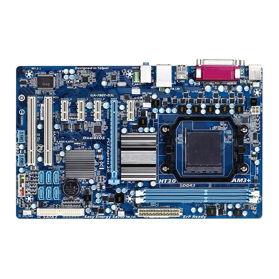
Page 5: Ga-780T-D3L Motherboard Layout
GA-780T-D3L Motherboard Layout SYS_FAN2 KB_USB ATX_12V Socket AM3+ COAXIAL R_USB CPU_FAN GA-780T-D3L AUDIO AMD 760G PCIEX1_1 F_AUDIO Realtek/Atheros PCIEX16 GbE LAN PWR_FAN PCIEX1_2 CODEC PCIEX1_3 AMD SB710 M_BIOS PCIEX1_4 B_BIOS SPDIF_O SATA2 CLR_CMOS PCI1 PCI2 F_PANEL F_USB2 SYS_FAN1 F_USB1 Box Contents... -
Page 6: Ga-780T-D3L Motherboard Block Diagram
GA-780T-D3L Motherboard Block Diagram CPU CLK+/- (200 MHz) PCIe CLK AM3+/AM3 CPU DDR3 1666 (O.C.)/1333/1066 MHz (100 MHz) Dual Channel Memory 1 PCI Express x16 Hyper Transport 3.0 PCI Express x16 AMD 760G PCI Express Bus PCIe CLK (100 MHz) -
Page 7: Chapter 1 Hardware Installation
Chapter 1 Hardware Installation Installation Precautions The motherboard contains numerous delicate electronic circuits and components which can become damaged as a result of electrostatic discharge (ESD). Prior to installation, carefully read the user's manual and follow these procedures: Prior to installation, make sure the chassis is suitable for the motherboard. •... -
Page 8: Product Specifications
1-2 Product Specifications AM3+ Socket: Š AMD AM3+ FX processors AMD AM3 Phenom II processors/ AMD Athlon II processors ™ ™ (Go to GIGABYTE's website for the latest CPU support list.) Hyper Transport 4400 MT/s Š North Bridge: AMD 760G Š Chipset South Bridge: AMD SB710 Š... - Page 9 Internal 2 x USB 2.0/1.1 headers Š Connectors 1 x Clear CMOS jumper Š Back Panel 1 x PS/2 keyboard/mouse port Š Connectors 1 x parallel port Š 1 x serial port Š 1 x coaxial S/PDIF Out connector Š 6 x USB 2.0/1.1 ports Š...
-
Page 10: Installing The Cpu
Installing the CPU Read the following guidelines before you begin to install the CPU: Make sure that the motherboard supports the CPU. • (Go to GIGABYTE's website for the latest CPU support list.) Always turn off the computer and unplug the power cord from the power outlet before installing •... -
Page 11: Installing The Memory
Installing the Memory Read the following guidelines before you begin to install the memory: Make sure that the motherboard supports the memory. It is recommended that memory of the • same capacity, brand, speed, and chips be used. (Go to GIGABYTE's website for the latest supported memory speeds and memory modules.) Always turn off the computer and unplug the power cord from the power outlet before installing •... -
Page 12: Back Panel Connectors
Back Panel Connectors USB 2.0/1.1Port The USB port supports the USB 2.0/1.1 specification. Use this port for USB devices such as a USB key- board/mouse, USB printer, USB flash drive and etc. PS/2 Keyboard or PS/2 Mouse Port Use this port to connect a PS/2 keyboard or PS/2 mouse. Parallel Port Use the parallel port to connect devices such as a printer, scanner and etc. -
Page 13: Internal Connectors
Internal Connectors ATX_12V F_PANEL CPU_FAN F_AUDIO SYS_FAN1/SYS_FAN2 SPDIF_O PWR_FAN F_USB1/F_USB2 CLR_CMOS SATA2 0/1/2/3/4/5 Read the following guidelines before connecting external devices: First make sure your devices are compliant with the connectors you wish to connect. • Before installing the devices, be sure to turn off the devices and your computer. Unplug the •... - Page 14 1/2) ATX_12V/ATX (2x2 12V Power Connector and 2x12 Main Power Connector) With the use of the power connector, the power supply can supply enough stable power to all the components on the motherboard. Before connecting the power connector, first make sure the power supply is turned off and all devices are properly installed.
- Page 15 3/4/5) CPU_FAN/SYS_FAN1/SYS_FAN2/PWR_FAN (Fan Headers) The motherboard has a 4-pin CPU fan header (CPU_FAN), a 4-pin (SYS_FAN1) and a 3-pin (SYS_ FAN2) system fan headers, and a 3-pin power fan header (PWR_FAN). Most fan headers possess a foolproof insertion design. When connecting a fan cable, be sure to connect it in the correct orientation (the black connector wire is the ground wire).
- Page 16 DEBUG DEBUG PORT PORT DEBUG DEBUG PORT PORT DEBUG DEBUG PORT PORT 7) SATA2 0/1/2/3/4/5 (SATA 3Gb/s Connectors) The SATA connectors conform to SATA 3Gb/s standard and are compatible with SATA 1.5Gb/s standard. Each SATA connector supports a single SATA device. The AMD SB710 controller supports RAID 0, RAID 1, RAID 10, and JBOD.
-
Page 17: F_Panel (Front Panel Header)
9) F_PANEL (Front Panel Header) Connect the power switch, reset switch, speaker, and system status indicator on the chassis to this header according to the pin assignments below. Note the positive and negative pins before connecting the cables. Message/Power/ Power Speaker Sleep LED Switch... - Page 18 10) F_AUDIO (Front Panel Audio Header) The front panel audio header supports Intel High Definition audio (HD) and AC'97 audio. You may connect your chassis front panel audio module to this header. Make sure the wire assignments of the module con- nector match the pin assignments of the motherboard header.
- Page 19 12) F_USB1/F_USB2 (USB Headers) The headers conform to USB 2.0/1.1 specification. Each USB header can provide two USB ports via an optional USB bracket. For purchasing the optional USB bracket, please contact the local dealer. Pin No. Definition Power (5V) Power (5V) USB DX- USB DY-...
-
Page 20: Chapter 2 Bios Setup
Chapter 2 BIOS Setup To access the BIOS Setup program, press the <Delete> key during the POST when the power is turned on. To see more advanced BIOS Setup menu options, you can press <Ctrl> + <F1> in the main menu of the BIOS Setup program. -
Page 21: The Main Menu
The Main Menu Once you enter the BIOS Setup program, the Main Menu (as shown below) appears on the screen. Use arrow keys to move among the items and press <Enter> to accept or enter a sub-menu. (Sample BIOS Version: D5) CMOS Setup Utility-Copyright (C) 1984-2012 Award Software MB Intelligent Tweaker(M.I.T.) Load Fail-Safe Defaults... -
Page 22: Mb Intelligent Tweaker(M.i.t.)
MB Intelligent Tweaker(M.I.T.) CMOS Setup Utility-Copyright (C) 1984-2012 Award Software MB Intelligent Tweaker(M.I.T.) Item Help CPU Clock Ratio [Auto] 2800Mhz CPU NorthBridge Freq. [Auto] 2000Mhz Menu Level Core Performance Boost [Enabled] (Note) CPB Ratio [Auto] (Note) Turbo CPB [Disabled] (Note) CPU Host Clock Control [Auto]... - Page 23 CPU Frequency(MHz) & Allows you to manually set the CPU host frequency. The adjustable range is from 200 MHz to 500 MHz. This option is configurable only when CPU Host Clock Control is set to Manual. Important It is highly recommended that the CPU frequency be set in accordance with the CPU specifications.
- Page 24 CMOS Setup Utility-Copyright (C) 1984-2012 Award Software DRAM Configuration Item Help CS/ODT Drive Strength [Auto] 1.5x [Auto] 2.0x Menu Level CKE Drive Strength [Auto] 1.5x [Auto] 2.0x **DCTs Addr/Cmd Timing** DCT0 DCT1 Addr/Cmd Setup Time [Auto] [Auto] 1/2T Addr/Cmd Fine Delay [Auto] 22/64 [Auto]...
- Page 25 DQS Drive Strength & Options are: Auto (default), 0.75x, 1.0x, 1.25x, 1.5x. Data Drive Strength & Options are: Auto (default), 0.75x, 1.0x, 1.25x, 1.5x. MEMCLK Drive Strength & Options are: Auto (default), 0.75x, 1.0x, 1.25x, 1.5x. Addr/Cmd Drive Strength & Options are: Auto (default), 1.0x, 1.25x, 1.5x, 2.0x.
-
Page 26: Standard Cmos Features
CPU Voltage Control & Allows you to set the CPU voltage. Auto sets the CPU voltage as required. The adjustable range is dependent on the CPU being installed. (Default: Normal) Note: Increasing CPU voltage may result in damage to your CPU or reduce the useful life of the CPU. CPU NB VID Control &... -
Page 27: Advanced Bios Features
IDE Channel 2, 3 Master/Slave & IDE Auto-Detection Press <Enter> to autodetect the parameters of the IDE/SATA device on this channel. Extended IDE Drive Configure your IDE/SATA devices by using one of the two methods below: Auto Lets the BIOS automatically detect IDE/SATA devices during the POST. •... - Page 28 Enabled If a CPU that supports hardware C1E is installed, the BIOS will automatically enable the hardware C1E function. If not, the BIOS will enable the software C1E function. Disabled Disables the C1E function. Virtualization & Virtualization allows a platform to run multiple operating systems and applications in independent partitions. With virtualization, one computer system can function as multiple virtual systems.
-
Page 29: Integrated Peripherals
HDD S.M.A.R.T. Capability & Enables or disables the S.M.A.R.T. (Self Monitoring and Reporting Technology) capability of your hard drive. This feature allows your system to report read/write errors of the hard drive and to issue warnings when a third party hardware monitor utility is installed. (Default: Disabled) Away Mode &... - Page 30 OnChip SATA Port4/5 Type (AMD SB710 South Bridge, SATA2 4/5 connectors) & This option is configurable only when OnChip SATA Type is set to RAID or AHCI. Configures the operating mode of the integrated SATA2 4/5 connectors. Disables RAID for the SATA controller and configures the SATA controller to PATA mode. (Default) As SATA Type The mode depends on the OnChip SATA Type settings.
-
Page 31: Power Management Setup
Onboard Audio Function & Enables or disables the onboard audio function. (Default: Enabled) If you wish to install a 3rd party add-in audio card instead of using the onboard audio, set this item to Disabled. USB Controllers & Enables or disables the integrated USB controllers. (Default: Enabled) Disabled will turn off all of the USB functionalities below. - Page 32 S3(STR) Enables the system to enter the ACPI S3 (Suspend to RAM) sleep state (default).In S3 sleep state, the system appears to be off and consumes less power than in the S1 state. When signaled by a wake-up device or event, the system resumes to its working state exactly where it was left off.
-
Page 33: Pc Health Status
Memory The system returns to its last known awake state upon the return of the AC power. Power-On by Alarm & Determines whether to power on the system at a desired time. (Default: Disabled) If enabled, set the date and time as following: Date (of Month) Alarm: Turn on the system at a specific time on each day or on a specific day in a month. - Page 34 Reset Case Open Status & Keeps or clears the record of previous chassis intrusion status. Enabled clears the record of previous chassis intrusion status and the Case Opened field will show "No" at next boot. (Default: Disabled) Case Opened & Displays the detection status of the chassis intrusion detection device attached to the motherboard CI header.
-
Page 35: Load Fail-Safe Defaults
Load Fail-Safe Defaults CMOS Setup Utility-Copyright (C) 1984-2012 Award Software MB Intelligent Tweaker(M.I.T.) Load Fail-Safe Defaults Standard CMOS Features Load Optimized Defaults Advanced BIOS Features Set Supervisor Password Integrated Peripherals Set User Password Power Management Setup Save &... -
Page 36: Set Supervisor/User Password
2-11 Set Supervisor/User Password CMOS Setup Utility-Copyright (C) 1984-2012 Award Software MB Intelligent Tweaker(M.I.T.) Load Fail-Safe Defaults Standard CMOS Features Load Optimized Defaults Advanced BIOS Features Set Supervisor Password Integrated Peripherals Set User Password Power Management Setup Save &... -
Page 37: Exit Without Saving
2-13 Exit Without Saving CMOS Setup Utility-Copyright (C) 1984-2012 Award Software MB Intelligent Tweaker(M.I.T.) Load Fail-Safe Defaults Standard CMOS Features Load Optimized Defaults Quit Without Saving (Y/N)? N Advanced BIOS Features Set Supervisor Password Integrated Peripherals Set User Password ... -
Page 38: Chapter 4 Appendix
Chapter 4 Appendix 4-1 Configuring SATA Hard Drive(s) Before you begin Please prepare: At least two SATA hard drives (to ensure optimal performance, it is recommended that you use two hard • drives with identical model and capacity). If you do not want to create RAID, you may prepare only one hard drive. - Page 39 Press <Ctrl>+<Y> keys to save the information. The window below will appear. Press <Ctrl>+<Y> to clear the MBR or press other keys to ignore this option. Fast Initialization option has been selected It will erase the MBR data of the disk. <Press Ctrl-Y key if you are sure to erase it>...
-
Page 40: Regulatory Statements
Regulatory Statements Regulatory Notices This document must not be copied without our written permission, and the contents there of must not be imparted to a third party nor be used for any unauthorized purpose. Contravention will be prosecuted. We believe that the information contained herein was accurate in all respects at the time of printing. - Page 41 - 41 -...
- Page 42 - 42 -...
- Page 43 - 43 -...
- Page 44 Contact Us GIGA-BYTE TECHNOLOGY CO., LTD. Address: No.6, Bao Chiang Road, Hsin-Tien Dist., New Taipei City 231,Taiwan TEL: +886-2-8912-4000, FAX: +886-2-8912-4003 Tech. and Non-Tech. Support (Sales/Marketing) : http://ggts.gigabyte.com.tw WEB address (English): http://www.gigabyte.com WEB address (Chinese): http://www.gigabyte.tw You may go to the GIGABYTE website, select your language in the language list on the top right corner of the website. GIGABYTE Global Service System •...