Table of Contents
Advertisement
Advertisement
Table of Contents
Troubleshooting

Related Manuals for Cisco DPC2203C


Summary of Contents for Cisco DPC2203C
- Page 1 72-4017315-01 Rev B DPC2203C VoIP Cable Modem Installation and Operation Guide...
- Page 3 Please Read Important Please read this entire guide. If this guide provides installation or operation instructions, give particular attention to all safety statements included in this guide.
-
Page 4: Trademark Acknowledgements
Trademark Acknowledgements Cisco and the Cisco logo are trademarks or registered trademarks of Cisco and/or its affiliates in the U.S. and other countries. To view a list of cisco trademarks, go to this URL: www.cisco.com/go/trademarks. DOCSIS, EuroDOCSIS, EuroPacketCable, and PacketCable are trademarks of Cable Television Laboratories, Inc. -
Page 5: Important Safety Instructions
IMPORTANT SAFETY INSTRUCTIONS IMPORTANT SAFETY INSTRUCTIONS Notice to Installers The servicing instructions in this notice are for use by qualified service personnel only. To reduce the risk of electric shock, do not perform any servicing other than that contained in the operating instructions, unless you are qualified to do so. -
Page 6: Aviso A Los Instaladores De Sistemas Catv
IMPORTANT SAFETY INSTRUCTIONS Mitteilung für CATV-Techniker Die in dieser Mitteilung aufgeführten Wartungsanweisungen sind ausschließlich für qualifiziertes Fachpersonal bestimmt. Um die Gefahr eines elektrischen Schlags zu reduzieren, sollten Sie keine Wartungsarbeiten durchführen, die nicht ausdrücklich in der Bedienungsanleitung aufgeführt sind, außer Sie sind zur Durchführung solcher Arbeiten qualifiziert. 20070112 SysInstaller 820 German Aviso a los instaladores de sistemas CATV Las instrucciones de reparación contenidas en el presente aviso son para uso exclusivo por parte de... - Page 7 IMPORTANT SAFETY INSTRUCTIONS Read These Instructions Keep These Instructions Heed All Warnings Follow All Instructions Power Source Warning A label on this product indicates the correct power source for this product. Operate this product only from an electrical outlet with the voltage and frequency indicated on the product label. If you are uncertain of the type of power supply to your home or business, consult your service provider or your local power company.
- Page 8 IMPORTANT SAFETY INSTRUCTIONS Prevent Power Cord Damage Protect the power cord from being walked on or pinched, particularly at plugs, convenience receptacles, and the point where the cord exits from the apparatus. Handling Optional, Rechargeable Battery This product may contain a rechargeable Lithium-Ion battery to provide stand-by operation in the event of an AC power failure.
- Page 9 IMPORTANT SAFETY INSTRUCTIONS Accessories Warning WARNING: Avoid electric shock and fire hazard! Only use attachments/accessories specified by your service provider or the manufacturer. Service Warnings WARNING: Avoid electric shock! Do not open the cover of this product. Opening or removing the cover may expose you to dangerous voltages. If you open the cover, your warranty will be void.
-
Page 11: Fcc Compliance
Consult the cable company or an experienced radio/television technician for help. Any changes or modifications not expressly approved by Cisco Systems, Inc., could void the user's authority to operate the equipment. The information shown in the FCC Declaration of Conformity paragraph below is a requirement of the FCC and is intended to supply you with information regarding the FCC approval of this device. -
Page 13: Table Of Contents
Contents IMPORTANT SAFETY INSTRUCTIONS FCC Compliance About This Guide Chapter 1 Introducing the Model DPC2203C VoIP Cable Modem 1 DPC2203C Features ......................... 2 DPC2203C Components ......................4 Theory of Operation ........................ 7 Chapter 2 Installing the DPC2203C for Internet Service Before You Begin ........................ - Page 14 Contents Chapter 5 Operating the DPC2203C WebWizard ..........................58 Appendix A Specifications Technical Specifications ......................68 Appendix B Cable Modem Warranty and RMA Information Warranty and RMA Information ..................74 72-4017315-01 Rev B...
-
Page 15: About This Guide
About This Guide About This Guide Introduction This installation and operation guide applies to the Model DPC2203C voice over Internet Protocol (VoIP) Cable Modems. These models are cable modems with an embedded media terminal adapter (EMTA) including two RJ-11 telephone ports supporting two-line voice services, a 10/100Base-T Ethernet port, and a USB 1.1 port... - Page 16 About This Guide Document Version This is the second release of this document. 72-4017315-01 Rev B...
-
Page 17: Chapter 1 Introducing The Model Dpc2203C Voip Cable Modem
Ion cartridge-style battery for convenient backup power. This chapter provides an overview of the outstanding design and performance features of the DPC2203C, the front and back panel components of the cable modem, and a theory of operation for cable modems for successful installation and operation of the cable modem. -
Page 18: Dpc2203C Features
Chapter 1 Introducing the Model DPC2203C VoIP Cable Modem DPC2203C Features This section contains an overview of some of the design and performance features of the DPC2203C. Design and Performance Features The DPC2203C is designed to meet DOCSIS 2.0 and 1.1 specifications along with ®... - Page 19 DPC2203C Features WebWizard The DPC2203C includes the WebWizard, a browser-based interface that facilitates cable modem set up and troubleshooting. The WebWizard verifies set-up and troubleshooting results and eliminates the need to load additional setup software on the consumer premise equipment (CPE). In addition, as many as eight front-panel...
-
Page 20: Dpc2203C Components
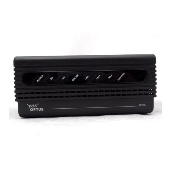
Chapter 1 Introducing the Model DPC2203C VoIP Cable Modem DPC2203C Components Front Panel Description The front panel of your cable modem provides status LEDs that indicate how well and at what state your cable modem is operating. See Functions of Front Panel LED Status Indicators (on page 38) for more information on front-panel LED status indicator functions. - Page 21 DPC2203C Components Notes: After the cable modem is successfully registered on the network, the POWER (LED 1), DS (LED 2), US (LED 3), and ONLINE (LED 4) LEDs illuminate continuously to indicate that the cable mode is active and fully operational ...
-
Page 22: Back Panel Description
Chapter 1 Introducing the Model DPC2203C VoIP Cable Modem Back Panel Description The following illustration shows the description and function of the back panel components on the DPC2203C. Important: Do not connect your PC to both the Ethernet and USB ports at the same time. -
Page 23: Theory Of Operation
Theory of Operation Theory of Operation This section summarizes the theory of operation for cable modems and provides a high-level overview of the operational stages for the cable modem. Reading this chapter provides a better understanding of how cable modems operate. Note: This section is not intended to be a specification for the cable modem. - Page 24 Chapter 1 Introducing the Model DPC2203C VoIP Cable Modem Downstream Scanning Routine The cable modem starts its own standard scanning algorithm. The scanning routine of the cable modem is now optimized to seek out the CMTS downstream channel as quickly as possible. The actual scanning process varies slightly depending on the television frequency channel plan for your particular country.
- Page 25 Theory of Operation WebWizard Gscan Function When installing a cable modem, you can speed up the process by using the WebWizard Gscan function. To access the WebWizard Gscan function, you must first connect a PC to the cable modem. Then, using your Web Browser, you can access the WebWizard Gscan function.
- Page 26 Chapter 1 Introducing the Model DPC2203C VoIP Cable Modem Establish IP Connectivity After completing the ranging and automatic adjustments stage, the cable modem attempts to establish Internet Protocol (IP) connectivity. In this stage, the cable modem obtains network connection information and a cable modem IP address from provisioning servers that are located on the network side of the CMTS interface.
- Page 27 Theory of Operation Notes: If the cable modem does not contain the software version requested by the configuration file, the cable modem requests that software version from the TFTP server. When the software installation is complete, the cable modem restarts the entire initialization process again at the scan for downstream channel stage.
-
Page 29: Chapter 2 Installing The Dpc2203C For Internet Service
Installing the DPC2203C for Internet Service Introduction This chapter provides information and procedures to assist you in placing, installing, configuring, operating, and troubleshooting the DPC2203C for high-speed Internet service. In This Chapter Before You Begin ................... 14 Install the Cable Modem ..............18 ... -
Page 30: Before You Begin
Chapter 2 Installing the DPC2203C for Internet Service Before You Begin This section provides the minimum requirements for installing the DPC2203C on your system and at user sites. Cable System Requirements To allow successful installation and operation, verify that your system meets the following minimum requirements: DOCSIS 2.0 or 1.1... -
Page 31: Hardware And Software Requirements
Before You Begin Hardware and Software Requirements This section provides hardware and software requirements for connecting your cable modem to a PC for high-speed Internet service. Note: You will also need an active cable input line and an Internet connection. PC Requirements A PC with a Pentium MMX 133 processor or greater ... - Page 32 Chapter 2 Installing the DPC2203C for Internet Service I Do Not Have a High-Speed Internet Access Account If you do not have a high-speed Internet access account, your service provider will set up your account and become your Internet Service Provider (ISP). Internet access enables you to send and receive e-mail, access the World Wide Web, and receive other Internet services.
- Page 33 Before You Begin I Already Have an Existing High-Speed Internet Access Account If you have an existing high-speed Internet access account, you must give your service provider the serial number and the MAC address of the cable modem. Refer to the serial number and MAC address information listed previously in this section. Note: You may not be able to continue to use your existing e-mail account with your cable modem.
-
Page 34: Install The Cable Modem
Chapter 2 Installing the DPC2203C for Internet Service Install the Cable Modem Installation Diagram The following diagram illustrates one of the various installation and connection options that are available to you. Note: Professional installation may be available. Contact your local service provider for further assistance. - Page 35 Install the Cable Modem Connect your PC to either the Ethernet port or the USB port using the appropriate data cable. Note: You can connect two separate PCs to the cable modem at the same time by connecting one to the Ethernet port and one to the USB port. Insert the AC power cord into the power connector on the back of the cable modem, and then plug the other end into an AC power source.
-
Page 36: Configure Tcp/Ip
Chapter 2 Installing the DPC2203C for Internet Service Configure TCP/IP This section contains instructions for configuring the cable modem to run in Microsoft Windows or Macintosh environments. In addition, TCP/IP protocol in a Microsoft Windows environment is different for the Windows 95, 98, 98SE, ME, 2000, or XP versions. - Page 37 Configure TCP/IP Click Yes to restart your computer when the Local Network window opens. The computer restarts. The TCP/IP protocol is now configured on your PC, and your Ethernet devices are ready for use. Try to access the Internet. If you cannot access the Internet, go to Troubleshooting the Installation (on page 35).
- Page 38 Chapter 2 Installing the DPC2203C for Internet Service Configuring TCP/IP on Macintosh Systems Click the Apple icon in the upper-left corner of the Finder. Scroll down to Control Panels, and then click TCP/IP. Click Edit on the Finder at the top of the screen. Scroll down to the bottom of the menu, and then click User Mode.
-
Page 39: Install Usb Drivers
Install USB Drivers Install USB Drivers This section contains instructions for installing the cable modem USB drivers if your PC is equipped with a USB interface and a Microsoft Windows 2000 or Windows XP operating system. The USB driver installation procedures are different for each operating system. - Page 40 Chapter 2 Installing the DPC2203C for Internet Service After the system finds the USB driver, the Digital Signature Not Found window opens and displays a confirmation message to continue the installation. Click Yes to continue the installation. The Found New Hardware Wizard window reopens with a message that the installation is complete.
-
Page 41: Chapter 3 Installing The Dpc2203C For Telephone Service
Chapter 3 Installing the DPC2203C for Telephone Service Introduction This chapter provides procedures to assist you in placing, installing, configuring, operating, and troubleshooting the DPC2203C for telephone service. In This Chapter Telephone Requirements ..............26 About the Battery .................. 27 ... -
Page 42: Telephone Requirements
Chapter 3 Installing the DPC2203C for Telephone Service Telephone Requirements This section provides hardware and software requirements for utilizing your cable modem for telephone service. Number of Telephone Devices The RJ-11 telephone-style connectors on the cable modem can each provide telephone service to multiple telephones, fax machines, and analog modems. -
Page 43: About The Battery
About the Battery About the Battery Your modem includes a rechargeable Lithium-Ion battery to provide stand-by operation in the event of an AC power failure. You can replace the battery without the use of any tools. WARNING: There is danger of explosion if the battery is mishandled or incorrectly replaced. - Page 44 Chapter 3 Installing the DPC2203C for Telephone Service Location of Battery The following illustration shows the location of the battery on the DPC2203C. Removing and Replacing the Battery Follow these steps to remove and replace the battery. You can remove and replace the battery without disconnecting the AC power source.
-
Page 45: Mount The Cable Modem On A Wall (Optional)
Mount the Cable Modem on a Wall (Optional) Mount the Cable Modem on a Wall (Optional) Before You Begin Before you begin, choose an appropriate mounting place. The wall can be made of cement, wood, or drywall. The mounting location should be free of obstructions on all sides, and the cables should be able to easily reach the cable modem without strain. -
Page 46: Wall Mounting Instructions
Chapter 3 Installing the DPC2203C for Telephone Service Location and Dimensions of the Wall-Mounting Slots The following illustration shows the location and dimensions of the wall-mounting slots on the bottom of the modem. Use the information on this page as a guide for mounting your modem to the wall. -
Page 47: Install The Cable Modem To Provide Telephone Service
Install the Cable Modem to Provide Telephone Service Install the Cable Modem to Provide Telephone Service The cable modem can be used to provide telephone service for one or two telephone lines. This section describes how to connect a single telephone, fax machine, analog telephone modem, or other telephone device to each telephone port on the cable modem. - Page 48 Chapter 3 Installing the DPC2203C for Telephone Service Installation Diagram The following diagram illustrates one of the various connection options that are available to you. To install the cable modem for telephone service Connect a telephone, fax machine, or analog modem to each of the appropriate RJ-11 ports on the cable modem.
- Page 49 Install the Cable Modem to Provide Telephone Service Connect the active RF coaxial cable to the CABLE connector on the back of the cable modem. The cable modem begins an automatic search to locate and sign on to the network that provides the telephone service. This process may take up to 5 minutes.
-
Page 51: Chapter 4 Troubleshooting The Installation
Chapter 4 Troubleshooting the Installation Introduction This chapter provides descriptions of possible cable modem performance and installation issues that may occur after the cable modem is installed. This chapter also shows specific examples of the condition as shown by the LED status indicators on the front panel of the cable modem. - Page 52 Chapter 4 Troubleshooting the Installation 72-4017315-01 Rev B...
-
Page 53: Troubleshooting Overview
Troubleshooting Overview Troubleshooting Overview This section provides a table that illustrates a summary of the visual status of the front-panel LED status indicators for the various cable modem situations and conditions described in this chapter. Summary of Front Panel LED Status Indicators (AC Power applied) The following table provides a summary of the visual status of the front panel LED status indicators for the various cable modem situations and conditions described in this chapter when AC power is applied to the cable modem. -
Page 54: Functions Of Front Panel Led Status Indicators
Chapter 4 Troubleshooting the Installation Functions of Front Panel LED Status Indicators Initial Power Up, Calibration, and Registration (AC Power applied) The following chart illustrates the sequence of steps and the corresponding appearance of the cable modem front panel LED status indicators during power up, calibration, and registration on the network when AC power is applied to the cable modem. - Page 55 Functions of Front Panel LED Status Indicators Normal Operations (AC Power applied) The following chart illustrates the appearance of the cable modem front panel LED status indicators during normal operations when AC power is applied to the cable modem. Front Panel LED Normal Operations POWER ONLINE...
-
Page 56: Special Conditions
Chapter 4 Troubleshooting the Installation Special Conditions The following chart describes the appearance of the cable modem front panel LED status indicators during special conditions to show when you have been denied network access, when the modem is operating on battery power, or when a software download is in progress. -
Page 57: Powering Options
Powering Options Powering Options Description The cable modem can operate from standard AC power or from battery power when there is a loss of AC power. After a cable modem powers on, it performs an internal self test to ensure proper initialization of the cable modem. When the self-test is complete, the cable modem will begin normal operation if AC power is available. - Page 58 Chapter 4 Troubleshooting the Installation Check and Correct Verify correct connection of the power cord to the cable modem. Verify correct connection of the power cord to an AC electrical outlet. If a wall switch controls the AC electrical outlet, verify that the wall switch is in the ON position.
-
Page 59: No Downstream Signal Lock
No Downstream Signal Lock No Downstream Signal Lock After a cable modem powers on and performs an internal self-test, the cable modem starts to scan for the CMTS downstream channel. The cable modem start its standard scanning algorithm. Note: For more information on this process, see Scan for Downstream Channel (on page 7). - Page 60 Chapter 4 Troubleshooting the Installation Is the ratio outside of the operating range? If yes, correct the downstream channel to the cable modem. If no, go to step 6. Check the status of the CMTS. Check the status of the CMTS signal on the node attached to the cable modem. 72-4017315-01 Rev B...
-
Page 61: Ranging Not Complete
Ranging Not Complete Ranging Not Complete Description After the cable modem finds the CMTS downstream channel and upstream parameters, it starts the ranging and automatic adjustments stage. This stage adjusts the timing offset and the power level for communication with the CMTS. Note: For more information on this process, see Adjust Timing Offset and Power Level (on page 9). - Page 62 Chapter 4 Troubleshooting the Installation Is the upstream level or the ratio outside of the operating range? If yes, correct the upstream channel to the cable modem. If no, go to step 5. Check the status of the CMTS. Check the status of the CMTS signal on the node attached to the cable modem.
-
Page 63: Ip Connectivity Not Complete
IP Connectivity Not Complete IP Connectivity Not Complete Description After completing the ranging stage, the cable modem then tries to establish IP connectivity. In this process the cable modem obtains network connection information and a cable modem IP address from provisioning servers located on the network side of the CMTS interface. - Page 64 Chapter 4 Troubleshooting the Installation Check and Correct Using the Web browser on the PC attached to the cable modem, access the WebWizard by entering the following IP address: http://192.168.100.1. The Web browser accesses the WebWizard and the Default page opens. Open the Signal page, and then select Cable Modem Status.
-
Page 65: Registration Not Complete
Registration Not Complete Registration Not Complete Description In this phase, the cable modem requests the time of day and the configuration file for the cable modem. The configuration file contains operational parameters for how the user wants the cable modem to operate on the system. If the cable modem receives an invalid configuration file, it may not be able to complete the registration process. - Page 66 Chapter 4 Troubleshooting the Installation Check and Correct Using the Web browser on the PC attached to the cable modem, access the WebWizard by entering the following IP address: http://192.168.100.1. The Web browser accesses the WebWizard and the Default page opens. Open the Signal page, and then select Cable Modem Status.
-
Page 67: Troubleshooting For High-Speed Data Installations
Troubleshooting for High-Speed Data Installations Troubleshooting for High-Speed Data Installations I cannot connect to the Internet Verify that the plug to your cable modem AC power is properly inserted into an electrical outlet. Verify that your cable modem AC power cord is not plugged into an electrical ... - Page 68 Chapter 4 Troubleshooting the Installation My cable modem does not recognize the cable network The cable modem works with a standard, 75-ohm, RF coaxial cable. If you are using a different cable, your cable modem will not function properly. Contact your service provider to determine if you are using the correct cable.
- Page 69 Troubleshooting for High-Speed Data Installations Click OK to close the IP Configuration window, you have completed this procedure. Note: If you cannot access the Internet, contact your service provider for further assistance. Renewing the IP Address on Macintosh Systems Close all open programs. Open your Preferences folder.
-
Page 70: Troubleshooting For Telephony Installations
Chapter 4 Troubleshooting the Installation Troubleshooting for Telephony Installations This section provides troubleshooting suggestions and check and correct tips for telephony installations. Common Troubleshooting Suggestions The modem does not register a cable connection The modem works with a standard, 75-ohm, RF coaxial cable. If you are using a different cable, your cable modem will not function properly. -
Page 71: Frequently Asked Questions
Troubleshooting for Telephony Installations Frequently Asked Questions Q. What if I don't subscribe to telephone service from my cable operator, can I still use the cable modem to make and receive phone calls? A. No. Telephone service is enabled for each telephone port on the cable modem by the cable telephony service provider. -
Page 73: Chapter 5 Operating The Dpc2203C
Operating the DPC2203C Introduction This chapter discusses the operational features related to the DPC2203C, the WebWizard, and Cable Modem Access Protection. This chapter also provides a description of WebWizard features along with sample WebWizard HTML pages. Access to these HTML pages is defined and configured by the system operator;... -
Page 74: Webwizard
Prior to registering on the network, the CPE has access to the WebWizard HTML pages. If enabled, the Basic, Advanced, and Cisco HTML pages are embedded links and are available to the user. Note: Access to these HTML pages is defined and configured by the system operator on the Technical Support page (see "Display the Technical Support... - Page 75 WebWizard Power Cycling and Reboots When power is restored after a power outage, the cable modem reboots normally. Reset The cable modem returns to the factory default level of access when you activate the factory reset switch. Press and hold the factory reset switch for 10 seconds to return the cable modem to its factory default settings.
- Page 76 Chapter 5 Operating the DPC2203C System Page This section provides an example of the System page. The System page displays system information about the cable modem, including the serial number, MAC address, software version, hardware version and software build and revision information.
- Page 77 WebWizard Signal Page This section provides an example of the System page. The System page displays system information about the cable modem, including the serial number, MAC address, software version, hardware version and software build and revision information. Signal Page Example The following illustration is an example of the Signal page.
- Page 78 Chapter 5 Operating the DPC2203C Basic Status Page This section provides an example of the Status page. The Status page displays information about the status of the communications between the cable modem and the cable modem network. Status Page Example The following illustration is an example of the Status page.
- Page 79 WebWizard Display the Cable Modem Event Log This section provides an example of the Event Log page. The Log page provides important information that can be used to resolve problems with your cable modem. Notes: The Event Log displays on both the Basic and Advanced tabs. ...
- Page 80 Chapter 5 Operating the DPC2203C EMTA Page This section provides an example of the EMTA page. The EMTA page provides important information about the current status of your cable modem. EMTA Page Example The following illustration is an example of the EMTA page.
- Page 81 WebWizard Display the Technical Support Page This section provides information about the Technical Support page. You can use the Technical Support page to set the subscriber access levels of each section of the cable modem. There are three sections you can control: Telnet Status ...
-
Page 83: Appendix A Specifications
Appx auto letter Specifications Appendix A Introduction This appendix contains the technical specifications for the DPC2203C. In This Appendix Technical Specifications ............... 68 72-4017315-01 Rev B... -
Page 84: Technical Specifications
Appendix A Specifications Technical Specifications DPC2203C Specifications Specifications Table The following table shows the technical specifications for the Model DPC2203C Cable Modem. Voice Specifications Call Signaling Protocol MGCP/NCS including configurable IPSec encryption Configurable to support LCS event signaling ... - Page 85 Technical Specifications Voice Specifications Hearing Impaired Services TDD support including detection of V.18 including Support Annex A Fax and Analog Modem support DSP-based Modem/Fax Tone detection and support for Voice Band Data Mode with auto-CODEC negotiation and auto-control of echo canceller, jitter buffer, and VAD Jitter Buffer Support Adaptive dynamically controlled Latency Control...
- Page 86 Appendix A Specifications Voice Specifications Call Feature Support Caller ID Call Waiting with Caller ID Call Conferencing (3-way calls) Configurable hook flash support Distinctive ringing (Configurable for up to 11 ring patterns per phone line) Ring splash ...
- Page 87 Technical Specifications RF Downstream Bandwidth 6 MHz Operating Level Range –15 to +15 dBmV Input Impedance 75 ohms RF Upstream Frequency Range 5 to 42 MHz Modulation QPSK 16 QAM 64 QAM 128 QAM TCM Maximum Data Rate 5.12 Mbps for QPSK ...
- Page 88 Standards Compliance and Compatibility The DPC2203C is designed to comply with the following standards: PacketCable 1.5 PacketCable 1.0 DOCSIS 2.0 WHQL Regulatory Compliance Approvals as required per country where the DPC2203C will be used. 72-4017315-01 Rev B...
-
Page 89: Appendix B Cable Modem Warranty And Rma Information
Appx auto letter Cable Modem Warranty and Appendix B RMA Information Introduction This appendix contains cable modem Warranty and Return Materials Authorization (RMA) information and includes an FAQ section. In This Appendix Warranty and RMA Information ............74 72-4017315-01 Rev B... -
Page 90: Warranty And Rma Information
Appendix B Cable Modem Warranty and RMA Information Warranty and RMA Information Cable Modem Warranty Information These cable modems enable you to access the Internet on your home computer through your cable TV line. Your local cable service provider becomes your Internet service provider. - Page 91 Warranty and RMA Information Provider, and you must properly pack the cable modem for shipment in the original packaging or equivalent. You will not be reimbursed for these expenses. If the cable modem is not insured and the cable modem is lost or damaged during transit, you are responsible for such loss or damage.
- Page 92 Appendix B Cable Modem Warranty and RMA Information What additional provisions should I be aware of? Because it is impossible for us to know the purposes for which you acquired this cable modem or the uses to which you will put this cable modem, you assume full responsibility for the selection of the cable modem and for its installation and use.
- Page 93 Service Contract entered into with us. An RMA fax request form is available upon request. Complete the RMA fax request form and fax it to: Customer Service, fax number: (770) 236-5477. Or you can contact Cisco Services. ...
- Page 94 Service Contract entered into with us. An RMA fax request form is available upon request. Complete the fax request form and fax it to: Customer Service, fax number: +44 (0)1923-269018. Or you can contact Cisco Services. Important: It is important to tell the Customer Service Representative the quantity of defective cable modems and defective external power supplies you are returning.
- Page 95 Warranty and RMA Information On issuance of an RMA number, goods returned to us should be clearly marked to the attention of Factory Service, at the address given by the customer service representative (CSR). A confirmation fax will be sent to you by the CSR that details the RMA number, product and quantities authorized, shipping address details, and RMA Terms and Conditions.
- Page 96 Appendix B Cable Modem Warranty and RMA Information 12 Return Material Authorization RMA numbers are only valid for 60 days. RMA numbers older than 60 days need to be revalidated by you before the equipment is returned. Failure to comply with the above may delay the processing of your RMA or result in the equipment being refused and being returned to you at your expense.
- Page 98 This document includes various trademarks of Cisco Systems, Inc. Please see the Notices section of this document for a list of the Cisco Systems, Inc. trademarks used in this document. Product and service availability are subject to change without notice.