EnGenius ESR6670 User Manual
11n wireless 3g router ieee 802.11 b/g/n
Hide thumbs
Also See for ESR6670:
- Quick start manual (36 pages) ,
- Datasheet (5 pages) ,
- Quick start manual (6 pages)
Table of Contents
Advertisement
Quick Links
Advertisement
Table of Contents

Related Manuals for EnGenius ESR6670


Summary of Contents for EnGenius ESR6670
- Page 1 ESR6670 11N Wireless 3G Router (IEEE 802.11 b/g/n) User Manual...
-
Page 2: Table Of Contents
PC N XP)............... 8 ETWORK DAPTER SETUP INDOWS 2.5. ESR6670 ......................10 RING UP SMART WIZARD ............................11 INITIAL SETUP ESR6670 ..........................14 AP ROUTER MODE ............................16 5.1..........................16 YSTEM 5.2..........................25 IZARD 5.3. INTERNET .......................... 26 5.4. -
Page 3: Revision History
Revision History Version Date Notes March 2, 2009 Initial... -
Page 4: Introduction
Congratulations on your purchase of ESR6670 3G Wireless Router. ESR6670 is compatible with the most popular 3G standards and 802.11g & 802.11b gadgets. ESR6670 is not only a Wireless Access Point, but also doubles as a 4-port full-duplex Switch that connects your wired-Ethernet devices together at incredible speeds. -
Page 5: Key Features
1.2. Key Features Features Advantages 3G Data Card Support Allows user to share 3G network among multiple users. It supports WCDMA (HSDPA), CDMA2000 and TD-SCDMA. Incredible Data Rate up to 300Mbps** Heavy data payloads such as MPEG video streaming IEEE 802.11b/g Compliant Fully Interoperable with IEEE 802.11b / IEEE 802.11g compliant devices with legacy protection... -
Page 6: Package Contents
1.3. Package Contents Open the package carefully, and make sure that none of the items listed below are missing. Do not discard the packing materials, in case of return; the unit must be shipped back in its original package. 1. SOHO Router 2. -
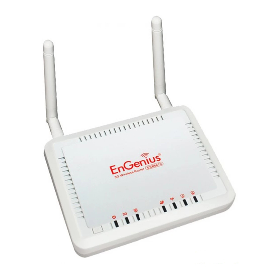
Page 7: Product Layout
1.4. Product Layout... - Page 8 Description Power 1 ( On-> red Test/reset default->blink) 1 ( Link-> green on, traffic->blink) 1 ( Link-> blue on, traffic->blink) Internet 1 ( Link-> blue on, traffic->blink) WLAN 1 ( Link-> blue on, traffic->blink) LAN1 1 ( Link-> blue on, traffic->blink) Interface Description Reset...
-
Page 9: Installation
Few Ethernet compatible CAT5 cables. 2.2. ESR6670 Placement You can place ESR6670 on a desk or other flat surface, or you can mount it on a wall. For optimal performance, place your Wireless Router in the center of your office (or your home) in a location that is away from any potential source of interference, such as a metal wall or microwave oven. -
Page 10: Setup Lan & 3G (Wan)
ADSL (Cable Modem): Connect Ethernet cable between WAN ports of your ADSL/CABLE modem & WAN port of ESR6670. Make sure your ADSL/CABLE modem is working well. Contact your ISP if you have any questions concerning the access... -
Page 11: Pc Network Adapter Setup (Windows Xp)
2.4. PC Network Adapter setup (Windows XP) Enter [Start Menu] select [Control panel] select [Network]. Select [Local Area Connection]) icon=>select [properties]... - Page 12 Select [Internet Protocol (TCP/IP)] =>Click [Properties]. Select the [General] tab. ESR6670 supports [DHCP] function, please select both [Obtain an IP address automatically] and [Obtain DNS server address automatically].
-
Page 13: Bring Up Esr6670
Connect the supplied power-adapter to the power inlet port and connect it to a wall outlet. Then, ESR6670 automatically enters the self-test phase. During self-test phase, Power LED will blink briefly, and then will be lit continuously to indicate that... -
Page 14: Smart Wizard
3. Smart Wizard Click <Next> to enter mode selection. Select the mode that ESR6670 is going to be and set its configurations. AP Repeater mode does not enable WAN interface, Setup Wizard will skip WAN Configuration. Click <Next> to automatically detect your Internet Network settings. - Page 15 You could choose your service type or select Others to setup WAN configurations manually. Smart Wizard has detected DHCP client. Configure the host name and MAC address of ESR6670. Click Next to proceed. Smart Wizard has finished setting up WAN Configuration. Click <Next> to proceed.
- Page 16 Enter the name for your wireless network (SSID) and security key Click <Next> to proceed To apply the entire configuration, click <Reboot>. NOTE: After Wireless settings are applied, you need to connect from your WLAN client with the security settings you just finished configuring. Remember the type of security &...
-
Page 17: Initial Setup Esr6670
4. Initial Setup ESR6670 ESR6670 uses web-interface for configuration to be accessed through your web browser, such as Internet Explorer or Firefox. - LOGIN Procedure 1. OPEN your browser (e.g. Internet Explorer). 2. Type http://192.168.0.1 in address bar and hit [Enter] button on your keyboard. - Page 18 3. Click <OK> to navigate into ESR6670 configuration home page. 4. You will see the home page of ESR6670 as follows.
-
Page 19: Ap Router Mode
5. AP Router Mode 5.1. System - Status This page allows you to monitor the current status of your router. System: You can see the Uptime, hardware information, serial number as well as firmware version information. WAN Settings: This section displays whether the WAN port is connected to a Cable/DSL connection. - Page 20 LAN Settings: This section displays the Router LAN port’s current information. It also shows whether the DHCP Server function is enabled / disabled. WLAN Settings: This section displays the current WLAN configuration settings. Wireless configuration details such as SSID, Security settings, BSSID, Channel number and mode of operation are briefly shown.
- Page 21 LAN IP IP address: 192.168.0.1. It is the router’s LAN IP address (the “Default Gateway” IP address of your LAN clients). It can be changed based on your own choice. IP Subnet Mask: 255.255.255.0 Specify a Subnet Mask for your LAN segment. 802.1d Spanning Tree: This is disabled by default.
- Page 22 Start IP: This is the beginning of the IP pool for DHCP client hosts. End IP:. This is the end of the IP pool for DHCP client hosts Domain name: The Domain Name for the existing or customized network.
- Page 23 - DHCP View the current LAN clients which are assigned with an IP Address by the DHCP-server. This page shows all DHCP clients (LAN PCs) currently connected to your network. The table shows the assigned IP address, MAC address and expiration time for each DHCP leased client.
- Page 24 - Schedule This page allows users to set up schedule function for Firewall and Power Saving Edit schedule options to allow configuration of firewall and power savings services. Fill in the schedule and select type of service. Click <Apply> to keep the settings.
- Page 25 The schedule table lists the pre-schedule service-runs. You can select any of the schedule record using the check box.
-
Page 26: Event Log
- Event Log View operation event log. This page shows the current system log of the Router. It displays any event occurred after system start up. At the bottom of the page, the system log can be saved <Save> to a local file for further processing or the system log can be cleared <Clear>... - Page 27 - Monitor Show histogram for network connection on WAN, LAN & WLAN. Auto refresh keeps information updated frequently. - Language This Wireless Router support multiple language of web pages, You could select your native language here.
-
Page 28: Wizard
5.2. Wizard Click Wizard to configure the Router. Setup wizard will now be displayed; check that the modem is connected and click <Next>. The details please refer to Smart Wizard <Page 13>. -
Page 29: Internet
Your 3G data card may take more than 20 seconds to initiate and respond to ESR6670. Please be patient and pay attention to the 3G LED on the top panel. Green Light on 3G LED signifies that your 3G card is ready. - Page 30 - Dynamic IP Use the MAC address when registering for Internet service, and do not change it unless required by your ISP. If your ISP used the MAC address of the Ethernet card as an identifier, connect only the PC with the registered MAC address to the Router and click the <Clone MAC Address>...
- Page 31 - Static IP If your ISP Provider has assigned a fixed IP address, enter the assigned IP address, Subnet mask, Default Gateway IP address, and Primary DNS and Secondary DNS (if available) of your ISP provider.
- Page 32 - Point-to-Point over Ethernet Protocol (PPPoE) Login / Password: Enter the PPPoE username and password assigned by your ISP Provider. Service Name: This is normally optional. Maximum Transmission Unit (MTU): This is the maximum size of the packets. Type: Enable the Automatic Connection option to automatically re-establish the connection when an application attempts to access the Internet again.
- Page 33 - Point-to-Point Tunneling Protocol (PPTP) PPTP allows the secure connection over the Internet by simply dialing in a local point provided by your ISP provider. The following screen allows client PCs to establish a normal PPTP session and provides hassle-free configuration of the PPTP client on each client PC. Click <Apply>...
- Page 34 - 3G Network ISP: It shows a list of supported 3G Network Internet Service Provider. APN Code: Enter APN if ISP requires it. Dial Number: Enter phone number if ISP requires it. User Name: Enter 3G network account / username Password: Enter 3G network account password Type: Keep Connection: Keep connection with or without the presence of traffic.
-
Page 35: Wireless Settings
5.4. Wireless Settings - Basic In basic setting page, you can set wireless Radio, Mode, Band, SSID, and Channel. Radio: You can turn on/off wireless radio. If wireless Radio is off, you cannot associate with AP through wireless. Mode: In this device, we support three operation modes which are AP router and AP route with WDS. - Page 36 ESSID1~4: ESSID is the name of your wireless network. It might be a unique name to identify this wireless device in the Wireless LAN. It is case sensitive and up to 32 printable characters. You might change the default ESSID for added security.
-
Page 37: Wds With Ap Router
- WDS with AP Router Wireless Distribution System, a system that enables the wireless interconnection of access point, allows a wireless network to be extended using multiple APs without a wired backbone to link them. Each WDS AP needs same channel and encryption type settings. MAC address 1~4: Please enter the MAC address(es) of the neighboring APs which participate in WDS. - Page 38 Fragment Threshold: This specifies the maximum size of a packet during the fragmentation of data to be transmitted. If you set this value too low, it will result in bad performance. RTS Threshold: When the packet size is smaller than the RTS threshold, the wireless router will not use the RTS/CTS mechanism to send this packet.
- Page 39 Data Rate: The “Data Rate” is the rate that this access point uses to transmit data packets. The access point will use the highest possible selected transmission rate to transmit the data packets. N Data Rate: The “Data Rate” is the rate that this access point uses to transmit data packets for N compliant wireless nodes.
- Page 40 Disabling “Broadcast ESSID” can provide better security. WMM: Wi-Fi MultiMedia if enabled supports QoS for experiencing better audio, video and voice in applications. Encryption: When you choose to disable encryption, it is very insecure to operate ESR6670. Enable 802.1x Authentication...
- Page 41 IEEE 802.1x is an authentication protocol. Every user must use a valid account to login to this Access Point before accessing the wireless LAN. The authentication is processed by a RADIUS server. This mode only authenticates users by IEEE 802.1x, but it does not encrypt the data during communication.
- Page 42 Authentication Type: There are two authentication types: "Open System" and "Shared Key". Both AP and wireless client must be configured with the same authentication type. Key Length: You can select the WEP key length for encryption, 64-bit or 128-bit. The larger the key will be the higher level of security is used, but the throughput will be lower.
- Page 43 WPA-Radius Encryption Wi-Fi Protected Access (WPA) is an advanced security standard. You can use an external RADIUS server to authenticate wireless stations and provide the session key to encrypt data during communication. It uses TKIP or CCMP (AES) to change the encryption key frequently. Press <Apply> button when you are done.
-
Page 44: Mac Address Filtering
- MAC Address Filtering This wireless router supports MAC Address Control, which prevents unauthorized clients from accessing your wireless network. Enable wireless access control: Enable the wireless access control function Adding an address into the list Enter the "MAC Address" and "Description" of the wireless station to be added and then click <Add>. - Page 45 WPS is the simplest way to establish a connection between the wireless clients and the wireless router. You don’t have to select the encryption mode and fill in a long encryption passphrase every time when you try to setup a wireless connection. You only need to press a button on both wireless client and wireless router, and the WPS will do the rest for you.
- Page 46 Authentication Mode: It shows the active authentication mode for the wireless connection. Passphrase Key: It shows the passphrase key that is randomly generated by the wireless router during the WPS process. You may need this information when using a device which doesn’t support WPS. Interface: If device is set to repeater mode, you can choose “Client”...
-
Page 47: Client List
- Client List This WLAN Client Table shows the Wireless client associate to this Wireless Router. - Policy The Router can allow you to set up the Wireless Access Policy. WAN Connection: Allow Wireless Client on specific SSID to access WAN port. Communication between Wireless clients: Allow Wireless Client to communicate with other Wireless Client on specific SSID. -
Page 48: Firewall Settings
5.5. Firewall Settings The Router provides extensive firewall protection by restricting connection parameters, thus limiting the risk of hacker attacks, and defending against a wide array of common Internet attacks. However, for applications that require unrestricted access to the Internet, you can configure a specific client/server as a Demilitarized Zone (DMZ). - Page 49 packets going to your WAN port IP address to a particular IP address in your LAN. The difference between the virtual server and the DMZ function is that the virtual server re-directs a particular service/Internet application (e.g. FTP, websites) to a particular LAN client/server, whereas DMZ re-directs all packets (regardless of services) from your WAN IP address to a particular LAN client/server.
- Page 50 - Denial of Service (DoS) The Router's firewall can block common hacker attacks, including Denial of Service, Ping of Death, Port Scan and Sync Flood. If Internet attacks occur the router can log the events. Ping of Death: Protections from Ping of Death attack. Discard Ping From WAN: The router’s WAN port will not respond to any Ping requests Port Scan: Protects the router from Port Scans.
-
Page 51: Mac Filter
- MAC Filter If you want to restrict users from accessing certain Internet applications / services (e.g. Internet websites, email, FTP etc.), and then this is the place to set that configuration. MAC Filter allows users to define the traffic type permitted in your LAN. You can control which PC client can have access to these services. - Page 52 Add PC MAC Address Fill in “LAN MAC Address” and <Description> of the PC that is allowed / denied to access the Internet, and then click <Add>. If you find any typo before adding it and want to retype again, just click <Reset> and the fields will be cleared. Remove PC MAC Address If you want to remove some PC from the "MAC Filtering Table", select the PC you want to remove in the table and then click <Delete Selected>.
- Page 53 - IP Filter Enable IP Filtering: Check to enable or uncheck to disable IP Filtering. Deny: If you select “Deny” then all clients will be allowed to access Internet except for the clients in the list below. Allow: If you select “Allow” then all clients will be denied to access Internet except for the PCs in the list below.
-
Page 54: Url Filter
- URL Filter You can block access to some Web sites from particular PCs by entering a full URL address or just keywords of the Web site. Enable URL Blocking: Enable or disable URL Blocking Add URL Keyword Fill in “URL/Keyword” and then click <Add>. You can enter the full URL address or the keyword of the web site you want to block. - Page 55 Remove URL Keyword If you want to remove some URL keywords from the "Current URL Blocking Table", select the URL keyword you want to remove in the table and then click <Delete Selected>. If you want remove all URL keywords from the table, click <Delete All> button. If you want to clear the selection and re-select again, just click <Reset>.
-
Page 56: Advanced Settings
5.6. Advanced Settings - Network Address Translation (NAT) Network Address Translation (NAT) allows multiple users at your local site to access the Internet through a single Public IP Address or multiple Public IP Addresses. NAT provides Firewall protection from hacker attacks and has the flexibility to allow you to map Private IP Addresses to Public IP Addresses for key services such as Websites and FTP. - Page 57 Enable Port Mapping: Enable or disable port mapping function. Description: description of this setting. Local IP: This is the local IP of the server behind the NAT firewall. Protocol: This is the protocol type to be forwarded. You can choose to forward “TCP” or “UDP”...
- Page 58 If you want to remove a Port Mapping setting from the "Current Port Mapping Table", select the Port Mapping setting that you want to remove in the table and then click D<Delete Selected>. If you want to remove all Port Mapping settings from the table, click <Delete All> button.
- Page 59 Enable Port Forwarding: Enable or disable Port Forwarding. Description: The description of this setting. Local IP / Local Port: This is the LAN Client/Host IP address and Port number that the Public Port number packet will be sent to. Protocol: Select the port number protocol type (TCP, UDP or both). If you are unsure, then leave it to the default “both”...
- Page 60 - Port Triggering (Special Applications) Some applications require multiple connections, such as Internet games, video Conferencing, Internet telephony and others. In this section you can configure the router to support multiple connections for these types of applications. Enable Trigger Port: Enable or disable the Port Trigger function. Trigger Port: This is the outgoing (Outbound) range of port numbers for this particular application.
- Page 61 selection. Once you have selected an application, select a location (1-5) in the “Add” selection box and then click the <Add> button. This will automatically list the Public Ports required for this popular application in the location (1-5) you specified. Add Port Triggering Fill in the "Trigger Port", "Trigger Type”, “Public Port”, "Public Type", "Public Port"...
- Page 62 - UPNP With UPnP, all PCs in you Intranet will discover this router automatically. So, you don’t have to configure your PC and it can easily access the Internet through this router. Enable/Disable UPnP: You can enable or Disable the UPnP feature here. After you enable the UPnP feature, all client systems that support UPnP, like Windows XP, can discover this router automatically and access the Internet through this router without having to configure anything.
- Page 63 - Quality of Service (QoS) QoS can let you classify Internet application traffic by source/destination IP address and port number. You can assign priority for each type of application and reserve bandwidth for it. The packets of applications with higher priority will always go first. Lower priority applications will get bandwidth after higher priority applications get enough bandwidth.
- Page 64 Unlimited Priority Queue: The LAN IP address will not be bounded in the QoS limitation. High/Low Priority Queue: This can put the packets in the protocol and port range to High/Low QoS Queue. Bandwidth Allocation: This can reserve / limit the throughput of specific protocols and port range. You can set the upper bound and Lower bound.
- Page 65 Policy: Specify the policy the QoS, Min option will reserve the selected data rate in QoS queue. Max option will limit the selected data rate in QoS queue. Rate: The data rate of QoS queue. Disabled: This could turn off QoS feature.
- Page 66 - Routing You can set enable Static Routing to let the router forward packets by your routing policy. Destination LAN IP: Specify the destination LAN IP address of static routing rule. Subnet Mask: Specify the Subnet Mask of static routing rule. Default Gateway: Specify the default gateway of static routing rule.
-
Page 67: Tools Settings
5.7. TOOLS Settings - Admin You can change the password required to log into the Router's system web-based management. By default, the password is: admin. Passwords can contain 0 to 12 alphanumeric characters, and are case sensitive. Old Password: Fill in the current password to allow changing to a new password. New Password: Enter your new password and type it again in Repeat New Password for verification purposes... - Page 68 Remote managemen This allows you to designate a host in the Internet the ability to configure the Router from a remote site. Enter the designated host IP Address in the Host IP Address field. Host Address: This is the IP address of the host in the Internet that will have management/configuration access to the Router from a remote site.
-
Page 69: Time Setup
- Time The Time Zone allows your router to reference or base its time on the settings configured here, which will affect functions such as Log entries and Firewall settings. Time Setup: Synchronize with the NTP server Time Zone: Select the time zone of the country you are currently in. The router will set its time based on your selection. - Page 70 PC Date and Time: This field would display the PC date and time. Daylight Savings: The router can also take Daylight Savings into account. If you wish to use this function, you must select the Daylight Savings Time period and check/tick the enable box to enable your daylight saving configuration.
- Page 71 - DDNS DDNS allows you to map the static domain name to a dynamic IP address. You must get an account, password and your static domain name from the DDNS service providers. This router supports DynDNS, TZO and other common DDNS service providers. Enable/Disable DDNS: Enable or disable the DDNS function of this router Server Address: Select a DDNS service provider Host Name: Fill in your static domain name that uses DDNS.
- Page 72 - Power Saving power in WLAN mode can be enabled / disabled in this page. - Diagnosis This page could let you diagnosis your current network status.
- Page 73 - Firmware This page allows you to upgrade the router’s firmware. To upgrade the firmware of your Router, you need to download the firmware file to your local hard disk, and enter that file name and path in the appropriate field on this page. You can also use the Browse button to find the firmware file on your PC.
- Page 74 - Back-up This page allows you to save the current router configurations. When you save the configurations, you also can re-load the saved configurations into the router through the Restore Settings. If extreme problems occur you can use the Restore to Factory Defaults to set all configurations to its original default settings.
- Page 75 - Reset You can reset the Router when system stops responding correctly or stop functions.
-
Page 76: Repeater Mode
6. Repeater Mode Repeater mode has limited settings compared to the AP mode. Choose “Repeater mode” on the top right corner of the configuration page. System restarts and connects to the IP address http://192.168..0.1 You will see the configuration homepage under “REPEATER” mode now. -
Page 77: System
6.1. System - Status System status section allows you to monitor the current status of your router. You can see the Uptime, hardware information, serial number as well as firmware version information. LAN Settings: This page displays the Router LAN port’s current LAN & WLAN information. WLAN Settings: Wireless configuration details such as SSID, Security settings, BSSID, Channel number, mode of operation are briefly shown. - Page 78 IP address: It is the router’s LAN IP address (Your LAN clients default gateway IP address). It can be changed based on your own choice. IP Subnet Mask: Specify a Subnet Mask for your LAN segment. 802.1d Spanning Tree: This is disabled by default. If 802.1d Spanning Tree function is enabled, this router will use the spanning tree protocol to prevent network loops.
- Page 79 The schedule table lists the pre-schedule service-runs. You can select any of them using the check box.
- Page 80 - Event Log View operation log of ESR6670. This page shows the current system log of the Router. It displays any event occurred after system start up. At the bottom of the page, the system log can be saved <Save> to a local file for further processing or the system log can be cleared <Clear>...
- Page 81 - Monitor Show the network packets histogram for network connection on WAN, LAN & WLAN. Auto refresh keeps information updated frequently. - Language This Wireless Router support multiple language of web pages, you could select your native language here.
-
Page 82: Wireless
6.2. Wireless -Basic You can set parameters that are used for the wireless stations to connect to this router. The parameters include Mode, ESSID, Channel Number and Associated Client. Radio: Enable or Disable Wireless function Band: Allows you to set the AP fixed at 802.11b, 802.11g or 802.11n mode. You can also select B+G mode to allow 802.11b and 802.11g clients at the same time. - Page 83 -Client List This WLAN Client Table shows the Wireless client associate to this Wireless Router.
- Page 84 -Policy The Router can allow you to set up the Wireless Access Policy. Communication between Wireless clients: Allow Wireless Client to communicate with other Wireless Client on specific SSID. Communication between Wireless clients and wired clients: Allow Wireless Client to communicate with other Wireless Client on specific SSID and Wired Client on the switch.
-
Page 85: Tools
6.3. Tools - Admin You can change the password required to log into the Router's system web-based management. By default, the password is: admin. Passwords can contain 0 to 12 alphanumeric characters, and are case sensitive. Old Password: Fill in the current password to allow changing to a new password. New Password: Enter your new password and in Repeat New Password for verification purposes Click <Apply>... - Page 86 Remote managemen This allows you to designate a host in the Internet the ability to configure the Router from a remote site. Enter the designated host IP Address in the Host IP Address field. Host Address: This is the IP address of the host in the Internet that will have management/configuration access to the Router from a remote site.
- Page 87 - Time The Time Zone allows your router to reference or base its time on the settings configured here, which will affect functions such as Event Log entries and Schedule settings. Time Setup: Synchronize with the NTP server Time Zone: Select the time zone of the country you are currently in. The router will set its time based on your selection.
- Page 88 PC Date and Time: This field would display the PC date and time. Daylight Savings: The router can also take Daylight Savings into account. If you wish to use this function, you must select the Daylight Savings Time period and check/tick the enable box to enable your daylight saving configuration.
- Page 89 - Power Saving power in WLAN mode can be enabled / disabled in this page. - Diagnosis This page could let you diagnosis your current network status.
- Page 90 - Firmware This page allows you to upgrade the router’s firmware. To upgrade the firmware of your Router, you need to download the firmware file to your local hard disk, and enter that file name and path in the appropriate field on this page. You can also use the Browse button to find the firmware file on your PC.
- Page 91 - Back-up The page allows you to save (Backup) the router’s current configuration settings. When you save the configuration setting (Backup) you can re-load the saved configuration into the router through the Restore selection. If extreme problems occur you can use the Restore to Factory Defaults selection, this will set all configurations to its original default settings (e.g.
- Page 92 - Reset You can reset the Router when system stops responding correctly or stop functions.
-
Page 93: Appendix A - Fcc Interference Statement
Appendix A – FCC Interference Statement Federal Communication Commission Interference Statement This equipment has been tested and found to comply with the limits for a Class B digital device, pursuant to Part 15 of the FCC Rules. These limits are designed to provide reasonable protection against harmful interference in a residential installation. -
Page 94: Appendix B - Ic Interference Statement
Appendix B – IC Interference Statement Industry Canada statement: This device complies with RSS-210 of the Industry Canada Rules. Operation is subject to the following two conditions: (1) This device may not cause harmful interference, and (2) this device must accept any interference received, including interference that may cause undesired operation.