Advertisement
Quick Links
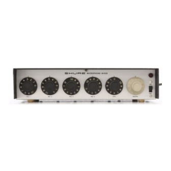
The Shure Models M68 and M68FC are five-channel,
portable microphone mixers for use with sound rein-
forcement, tape recording and audio-visual systems.
snu-
@
2 2 2 HARTREY AVE., EVANSTON, IL, 6 0 2 0 4 U S A
AREA CODE 3 1 2 / 8 6 6 - 2 2 0 0
CABLE SHUREMICRO
.----
---.-=--..
----
TWX. 91 0-231 -0048
TELEX 72-4349
M I C R O P H O N E S AND E L E C T R O N I C
COMPONENTS
Features:
DATA SHEET
MODELS M68 AND M68FC
MICROPHONE MIXERS
Four microphone inputs with individual slide swit-
ches for selection of low impedance (balanced or un-
balanced) or high impedance (unbalanced)
w
High-level auxiliary input suitable for tape, tuner, and
accessories
Individual volume control to balance each input
Master volume control to simultaneously control
level of all inputs
w
High- (unbalanced) or low-impedance (balanced or
unbalanced) microphone level output. lmpedance
selected to match microphone input of associated
amplifier
High-impedance auxiliary output
w
DC power supply jack supplies 28 volts dc for use
with accessories or may be used as power input in
connection with Model A67B Battery Power Supply
w
Facility for connecting two or more mixers together
to obtain additional microphone inputs (two mixers
connected together give a total of eight microphone
inputs and one auxiliary input)
w
Listed by Underwriters' Laboratories, Inc., and by
Canadian Standards Association as Certified
SPECIFICATIONS
Gain (at 1,000 Hz)
OUTPUTS
INPUT
Low Imp.
High Imp.
High Imp.
Mic.
Mic.
Low Imp. Mic.
.5 mV
produces
High Imp. Mic.
5 mV
produces
L5.5
m m
(7132
IN.)
OVERALL DIMENSIONS
FIGURE 1
Fre uency Response
Aat
+
3 dB, 40 Hz to 20,000 Hz
Hum-Noise
70 dB below rated output (Aux. Output)
Equivalent Input Noise
150 ohm source, 123 dB below 1 volt
Copyright 1984, Shure Brothers Inc.
27A872 (DH)
OUTPUT
Low Imp. Mic.
High Imp. Mic.
Auxiliary
1
Impedance
DESIGNED FOR USE WlTH
Balanced or unbalanced 25
1
600 ohm microphone-level
circuits
Unbalanced 10 to 50 kilohm
microphone-level circuits
Unbalanced high-impedance
(10 kilohms or greater)
auxiliary circuits
ACTUAL IMPEDANCE
150-300 ohms*
ACTUALIMPEDANCE
300 ohms
60 kilohms
40-70 kilohms'
INPUT
Low Imp. Mic
High Imp. Mic.
Auxiliary
30-40 kilohms'
2.5-3 kilohms*
DESIGNED FOR USE WITH
Balanced or unbalanced 25
to 600 ohm microphones
Unbalanced 10 to 50
kilohm microphones
100 ohm to 10 kilohm unbal-
anced high-level sources
'Depending upon control settings
Clipping Levels (minimum)
Distortion
Less than 1% total harmonic distortion when low-
impedance microphone output is at 20 mV level,
high-impedance microphone output is at 200 mV
level, and auxiliary output is at 2.0 volt level
Phase
All microphone inputs and outputs are in phase. Aux-
iliary input and output are in phase with each other
but out of phase with pin 3 of microphone connectors
Operating Voltage
AC Operation:
108-132 volts, 50160 Hz, 3W
DC Operation:
28 volts dc +.20%, 5 mA
Dimensions
See Figure 1
Net Weight
1.8 kg (4 Ib)
INPUT
Low Imp. Mic.
High Imp. Mic.
OUTPUT
Low Imp. Mic.
High Imp. Mic.
Auxiliary
INSTALLATION
CLIPPING LEVEL
30 mV
450 mV
CLIPPING LEVEL
60 mV
850 mV
4 volts
W A R N I N G
To reduce the risk of fire or electric shock, do not
expose this appliance to rain or extreme moisture.
Connection Between Components
For balanced-line connection use two-conductor,
shielded, low-capacity cable. For unbalanced (high-im-
pedance) connection, use single-conductor, shielded,
low-capacity cable.
Printed in U.S.A.
Advertisement

Related Manuals for Shure M68


Summary of Contents for Shure M68
- Page 1 M I C R O P H O N E S AND E L E C T R O N I C COMPONENTS Impedance The Shure Models M68 and M68FC are five-channel, portable microphone mixers for use with sound rein- INPUT...
- Page 2 CAUTION: The 28 Vdc input circuit of the M68 is not Grounding fused. An external 28 Vdc source should be provided If there should be objectionable hum, connect the metal chassis of the mixer to a good ground such as the with a 0.125A, 250V in-line fuse as a safety precaution.
- Page 3 PRINTED CIRCUIT BOARD ASSEMBLY W A R N I N G Voltages in this equipment are hazardous to life. Refer servicing to qualified service personnel. PARTS LIST PART PART DESCRIPTION QlY. NUMBER DIODE, SILICON (IN4002 OR EQUIVALENT) Dl, D2 RKC2l NEON PILOT LIGHT ASSEM.