Table of Contents
Advertisement
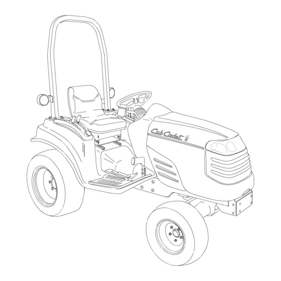
Operator's Manual
COMPACT TRACTOR
MODEL 7254
IMPORTANT: READ SAFETY RULES AND INSTRUCTIONS CAREFULLY
Warning
: This unit is equipped with an internal combustion engine and should not be used on or near any unimproved
forest-covered, brush-covered or grass-covered land unless the engine's exhaust system is equipped with a spark
arrester meeting applicable local or state laws (if any). If a spark arrester is used, it should be maintained in effective
working order by the operator. In the State of California the above is required by law (Section 4442 of the California Public
Resources Code). Other states may have similar laws. Federal laws apply on federal lands. A spark arrester for the
muffler is available through your nearest engine authorized service dealer or contact the service department, P.O. Box
361131 Cleveland, Ohio 44136-0019.
CUB CADET LLC P.O. BOX 361131 CLEVELAND, OHIO 44136-0019 [www.cubcadet.com]
PRINTED IN U.S.A.
FORM NO. 769-00001
(5/02)
Advertisement
Table of Contents

Related Manuals for Cub Cadet 7254


Summary of Contents for Cub Cadet 7254
- Page 1 Resources Code). Other states may have similar laws. Federal laws apply on federal lands. A spark arrester for the muffler is available through your nearest engine authorized service dealer or contact the service department, P.O. Box 361131 Cleveland, Ohio 44136-0019. CUB CADET LLC P.O. BOX 361131 CLEVELAND, OHIO 44136-0019 [www.cubcadet.com] PRINTED IN U.S.A. FORM NO. 769-00001...
- Page 2 NOTES...
-
Page 3: Table Of Contents
The dealer has trained service personnel familiar with the latest servicing information, is equipped with the latest tools, and has a complete line of genuine Cub Cadet service parts which assure proper fit and high quality. -
Page 4: Recording Model And Serial Number Information
ROPS Information Plate: ROPS Serial No. TRACTOR MODEL PLATE XXXXXXXXXXX XXXXXXXXXX Model Number Mfg. Date CUB CADET LLC P. O. BOX 361131 www.cubcadet.com CLEVELAND, OH 44136 DEALER LOCATOR PHONE NUMBER: 877-282-8684 Mfg. Date (Serial No.) Date of Mfg. Serial No. -
Page 5: Important Safe Operation Practices
IMPORTANT SAFE OPERATION PRACTICES WARNING: THIS SYMBOL POINTS OUT IMPORTANT SAFETY INSTRUCTIONS WHICH, IF NOT FOLLOWED, COULD ENDANGER THE PERSONAL SAFETY AND/OR PROPERTY OF YOURSELF AND OTHERS. READ AND FOLLOW ALL INSTRUCTIONS IN THIS MANUAL BEFORE ATTEMPTING TO OPERATE YOUR UNIT. FAILURE TO COMPLY WITH THESE INSTRUCTIONS MAY RESULT IN PERSONAL INJURY. -
Page 6: Slope Operation
• Maintain the weight balance of the tractor. Install front end weights to counterbalance heavy implements attached to the three point hitch. Do not operate the tractor with a light front end. • Any towed vehicle with a total weight exceeding that of the tractor should be equipped its own braking system that is operational from the tractor seat. - Page 7 • To prevent injury, do not adjust, unclog, clean, or service PTO driven equipment while the tractor engine is running. • Make certain all PTO shields are always installed. 5. SAFETY FRAME (ROPS) Your tractor is equipped with a rollover protective structure (ROPS) which must be maintained in a fully functional condition.
-
Page 8: Safety Labels
SAFETY LABELS STARTING INSTRUCTIONS 1. KNOW THE OPERATING AND SAFETY INSTRUCTIONS IN THE OPERATORS'S MANUAL AND ON THE TRACTOR. MOVE THROTTLE TO MID POSITION AND DEPRESS BRAKE PEDAL. TURN KEY TO THE START POSITION. STOPPING INSTRUCTIONS DISENGAGE PTO AND SET PARKING BRAKE. MOVE THROTTLE CONTROL TO MID POSITION AND TURN KEY OFF. - Page 9 SAFETY LABELS (Cont.) To avoid personal injury, keep PTO shield in place. Pull only from draw bar. pulling from any other point can cause rear overturn. Disengage PTO and stop engine before servicing tractor, or implements, or attaching or detaching implements. FAILURE TO FOLLOW ANY OF THE INSTRUCTIONS ABOVE CAN CAUSE SERIOUS INJURY TO THE OPERATOR, OR OTHER PERSONS.
-
Page 10: Section 1: Controls And Features
SECTION 1: CONTROLS AND FEATURES FLOORBOARD AND DASH PANEL MOUNTED CONTROLS Steering Wheel PTO Switch Throttle Handle Ignition Switch Brake Pedal Forward/Reverse Pedal * Steering Wheel and Seat Phantomed For Clarity Figure 1 Seat Adjustment Lever Differential Lock Pedal Parking Brake Lever Choke Control Knob Hazard Light Switch Headlight Switch... - Page 11 NOTE: References to LEFT and RIGHT indicate that side of the tractor when facing forward while seated in the drivers seat. Reference to FRONT indicates the grille end of the tractor; to REAR, the drawbar end. A. Steering Wheel The steering wheel is centered on the dash panel. It is used to change the direction (left or right) of the tractor while driving.
- Page 12 H. Differential Lock Pedal Diff. Lock Pedal Symbol Figure 6 Located at the rear of the left floor board, the differential lock pedal engages the transmission differential lock. The differential lock is used to gain additional trac- tion when operating the tractor on wet or loose soil. When the pedal is depressed the rear wheels of the tractor are prevented from rotating independently of one another.
- Page 13 If this warning lamp comes on during operation, check the charging system for possible causes and/or contact your Cub Cadet dealer. 4. Engine Oil Pressure Light The bulb illuminates when the ignition switch is in the ON position and should turn off shortly after the engine is started.
- Page 14 FENDER MOUNTED CONRTOLS AND FEATURES Fuel Fill Cap PTO Reverse Override Switch PTO Selection Lever Hydraulic Lift Lever Trans. Hi/Lo Shift Lever Cup Holder A. Fuel Fill Cap The fuel fill cap is located on the left fender beside the operator’s seat. WARNING: Never fill the fuel tank to the top of the filler neck.
- Page 15 E. Transmission Hi/Lo Range Shift Lever The Hi/Lo range shift lever is located on the right fender. The lever has two speed range settings and a neutral position. The lever must be shifted into either the high or low range prior to depressing the forward/reverse pedal to drive the tractor.
-
Page 16: Section 2: Operation
• In the event of an accident, have the ROPS carefully inspected and, if necessary, replaced by your Cub Cadet dealer. Do not attempt to repair the ROPS. SAFETY INTERLOCK SYSTEM This tractor is equipped with a safety interlock system for the protection of the operator. - Page 17 Cub Cadet dealer. COLD WEATHER STARTING Follow the normal engine starting instructions above. An optional engine coolant heater is available from your Cub Cadet dealer. This heater will aid in starting the tractor when ambient temperatures fall below 10°F (-12°C). THROTTLE HANDLE...
- Page 18 USING JUMPER CABLES TO START THE ENGINE WARNING: Batteries contain sulfuric acid and produce explosive gasses. Make certain the area is well ventilated, wear gloves and eye protection, and avoid sparks or flames near the battery. If the battery loses power and is unable to adequately crank the engine to start it, the aid of a booster battery may be necessary.
- Page 19 Avoid stopping when driving up a slope. If it is necessary to stop while driving up a slope, start up smoothly and carefully to reduce the possibility of flipping the tractor over backward. STOPPING THE TRACTOR • Fully depress the brake pedal to bring the tractor to a complete stop.
- Page 20 WARNING: Always maintain a tractor speed that allows for complete control and stability of the machine. Be aware of dangerous areas or conditions. NEUTRAL — Disengages the transmission drive. Shift the lever to the center of the slot. Use ONLY for towing or moving the tractor when not under power.
- Page 21 USING THE PTO SELECTION LEVER The position of the PTO selection lever will deter- mine whether the rear PTO, mid PTO, or both PTO’s will be engaged when the PTO switch is activated. WARNING: NEVER shift the PTO selec- tion lever while the PTO is engaged. Damage to internal components will occur.
- Page 22 USING THE PTO REVERSE OVERRIDE SWITCH The PTO reverse override switch, located on the left fender, allows the PTO to operate while the tractor is traveling in the reverse direction. Refer to Figure 19. • The PTO must first be engaged using the PTO switch on the dash panel.
- Page 23 Front Weights To counterbalance three point hitch mounted equipment, a weight bracket/bumper kit and cast iron weights are available from your Cub Cadet dealer. When mounting Cub Cadet equipment such as the 50" rotary tiller; 48" rotary cutter; or the 60" finish mower, the weight bracket and a minimum of four suitcase weights should be used.
-
Page 24: Section 3: Adjustments
SECTION 3: ADJUSTMENTS ADJUSTING THE SEAT For the comfort of the operator, a single lever adjustable seat is provided to set the fore to aft position of the seat. Adjust the seat to the most comfortable position that allows you to operate all controls and pedals. - Page 25 • The length of the upper hitch link is normally determined by the design of each implement. To adjust the upper hitch link, loosen the jam nut and turn the adjustment tube as shown in Figure 25. After the appropriate length is at- tained, tighten the jam nut.
- Page 26 Because of the precise nature of the feedback rod adjustment, it is recommended that any adjustment be per- formed by a qualified mechanic at your Cub Cadet dealer. If a high pitched squeal continues to emit from the...
-
Page 27: Section 4: Maintenance
32°F to 95°F Above 68°F Hydraulic Transmission Fluid Approx. 24 Qts. (6 Gal.) Approx. Use Cub Cadet Gear Lube 81 Oz. (2.5 Qts.) Needed 737-3034 (14.5 Oz. Cartridge) Use High Quality Permanent Type Antifreeze Approx. (Ethylene Glycol with corrosion and rust 3.5 Qts. - Page 28 LUBRICATION AND MAINTENANCE CHART (ILLUSTRATION)
-
Page 29: Lubrication And Maintenance Chart
LUBRICATION AND MAINTENANCE CHART Ref. Operation to be Performed Check Engine Oil Level Check Air Cleaner Check Engine Coolant Level Check and Clean Radiator Screen and Oil Cooler Fins Clean Air Cleaner Foam Element Change Engine Oil and Replace Oil Filter Retorque Front and Rear Wheel Bolts Check Transmission Oil Level... - Page 30 ACCESSING THE ENGINE COMPARTMENT WARNING: If the tractor has been recently operated, engine surfaces (including the radiator) will be HOT. Allow the engine to cool before open- ing the hood, or use extreme caution to avoid burns when the hood is open. To raise the hood, locate the latch release lever in the hood notch at the front of the tractor.
- Page 31 • Since battery acid is corrosive, do not pour it into any sink or drain. Before discarding an empty electrolyte container, rinse it thoroughly with a neutralizing solution. • NEVER connect (or disconnect) battery charger clips to the battery while the charger is turned on, as it can cause sparks.
- Page 32 TAIL LIGHT BULB REPLACEMENT Each tail light assembly has two light bulbs — a reverse indicator bulb (Cub Cadet no. 725-3263) and a tail light (Cub Cadet no. 725-3262). Access the back side of the tail lights from under the rear fender.
- Page 33 If the electrical system does not func- tion, check for blown fuses. See Figure 37 If you have a recurring problem with blown fuses, have the tractor’s electrical system checked by your Cub Cadet dealer. GOOD Figure 37 Accessing the Fuse Center The fuse center is located on the inside right of the dash panel.
- Page 34 Main Fuse The main fuse in the tractor wire harness protects the tractor’s entire electrical system. A blown main fuse will prevent battery current from passing though the harness. To replace the main fuse: • Raise the tractor hood and remove the right side panel.
-
Page 35: Changing Transmission/Hydraulic System Oil
• If the oil level is low, add Cub Cadet hydraulic oil. Loosely position a funnel in the fill hole so that there is enough clearance around the fun- nel to allow the transmission to vent while the oil is poured into the transmission. Fill ONLY to the full mark, never overfill the transmission. - Page 36 CHANGING HYDROSTATIC TRANSMISSION AND HYDRAULIC SYSTEM OIL FILTERS NOTE: Except for the initial break-in period oil filter change, the hydrostatic transmission and hydraulic system oil filters should be changed along with the hydrostatic transmission/hydraulic system oil after every 200 hours of operation. Initial Break-In Period Filter Change During the initial hours of tractor operation, contam- inants caused by the normal break-in of internal...
- Page 37 (See Figure 44). • If the oil level is low, add only enough Cub Cadet Gear Lube to bring the level to the full mark on the dipstick. NEVER overfill the axle housing.
- Page 38 Reinstall the drain plug after draining the oil. See Figure 46. • Fill the axle with Cub Cadet Gear Lube until the oil level reaches the full mark on the dipstick. Do not over fill the axle housing.
- Page 39 TIRE MAINTENANCE Check the tire air pressure after every 50 hours of operation or weekly. Keep the tires inflated to the recommended pressures. Improper inflation will shorten the service life of a tire. See the tire side wall, or the Tire Inflation chart, for proper inflation pressures.
- Page 40 Using a fuel stabilizer: • Read the product manufacturer’s instructions and recommendations. • Add to clean, fresh gasoline the correct amount stabilizer (approximately 6 gallons) of the fuel system. • Fill the fuel tank with treated fuel and run the engine for 2-3 minutes to get stabilized fuel into the carburetor.
-
Page 41: Section 5: Engine Information And Maintenance
SECTION 5: ENGINE INFORMATION AND MAINTENANCE The California Air Resources Board, the Environmental Protection Agency (EPA) , and Kawasaki Motors Corp., U.S.A. (hereinafter “Kawasaki”) are pleased to explain the Emission Control Systems Warranty on your Kawasaki small off-road engine. In California and other states, new small off-road engines must be designed, built and equipped to meet the stringent anti-smog standards. - Page 42 3. LIMITED LIABILITY. (a) The liability of Kawasaki under this Emission Control Systems Warranty is limited solely to the remedying of defects in materials or workmanship by any authorized Kawasaki small off-road engine dealer at its place of business during customary business hours. This warranty does not cover inconvenience or loss of use of the small off-road engine or transportation of the small off-road engine to or from the Kawasaki dealer.
- Page 43 ENGINE MAINTENANCE WARNING: Use care when servicing any component in the engine area. If the engine has recently been operated, components will be hot and could cause burns. Allow the engine to cool before servicing. WARNING: Before servicing the engine, place the tractor on a level surface, stop the engine, engage the parking brake, and remove the key from the...
- Page 44 ADDING ENGINE OIL WARNING: Never overfill the engine crankcase. The engine may overheat and/or damage may result if the crankcase is below the “ADD” mark or over the “FULL” mark on the dipstick. For best results, fill to the “FULL” mark on the dipstick as opposed to adding a given quantity of oil.
- Page 45 • Turn the valve drain cock fully clockwise to close the valve, and clean any residual oil from the valve. Refer to Figure 52. • Apply a light coating of clean oil on the gasket of the new oil filter. Thread the filter on by hand until the gasket contacts the filter mounting sur- face, then tighten the filter an additional 3/4 turn.
- Page 46 INSPECTION OF COOLING SYSTEM HOSES Check the cooling system hoses for any cracks or deterioration every 200 hours of operation. Check all hose connections for looseness. Replace any damaged hoses and tighten any loose connections. CHANGING THE ENGINE COOLANT The engine coolant should be drained and replaced with new coolant solution after every 400 hours of operation.
- Page 47 SERVICING THE FOAM PRECLEANER Wash the foam precleaner every 25 hours of operation. Wash more often when operating under extremely dusty conditions. Replace the precleaner if torn or otherwise damaged. Referring to Figure 56, wash the precleaner as follows: • Remove the knob and lift off the air cleaner cover and the washer.
-
Page 48: Section 6: Specifications
Drive ............On Demand 4WD Transmission Oil ......Cub Cadet Hydraulic/Transmission Fluid Transmission Capacity (Includes Hydraulics) . -
Page 49: Specifications
SPECIFICATIONS Hydraulic Lift System Type ............Auxiliary Pump-Gear Control . -
Page 50: Section 7: Optional Equipment And Accessories
SECTION 7: OPTIONAL EQUIPMENT AND ACCESSORIES When purchasing your tractor, you probably had it equipped for your particular needs at that time. You may later wish to obtain additional equipment or accessories to perform other tasks. Refer to the chart below for a list of optional equipment and accessories currently available through your Cub Cadet dealer. -
Page 52: Warranty
This limited warranty gives you specific legal rights, and you may also have other rights which vary from state to state. Cub Cadet LLC reserves the right to make changes in the design and other changes in its products at any time without notice and without incurring any obligation to product previously manufactured or purchased.