
Related Manuals for Lowrance Elite 5 DSI


Summary of Contents for Lowrance Elite 5 DSI
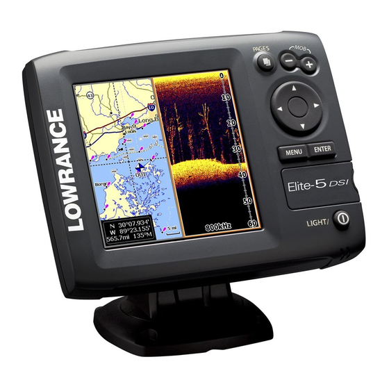
- Page 1 Elite 5 DSI, Elite 4 DSI & Mark 4 DSI Installation & Operation Operation manual manual...
- Page 2 Copyright © 2011 Navico All rights reserved. Lowrance® and Navico® are registered trademarks of Navico. Fishing Hot Spots® is a registered trademark of Fishing Hot Spots Inc. Navionics® is a registered trademark of Navionics, Inc. Navico may find it necessary to change or end our policies, regulations and special offers at any time. We reserve the right to do so without notice.
-
Page 3: Table Of Contents
Table of Contents Introduction ........3 Pages ..........11 Unit Controls ..........3 Steer Page..........11 Inserting microSD cards ......4 DSI Page ..........11 Basic Operation ....... 5 Chart/DSI page ........12 Chart Page ..........12 Setup wizard ..........5 Chart/Sonar split ........ - Page 4 Table of Contents Routes Screen ........23 Index ..........39 Trails Screen ......... 27 Specifications ........ 41 Orientation ..........29 Settings Menu........30 System........... 30 Settings .......... 30 Browse Files .......... 32 Saving Screenshots....... 32 Navigation..........33 Chart ............34 Sonar ............
-
Page 5: Introduction
Introduction Introduction Unit Controls Getting Started LIGhT/POwer: controls backlight To turn on/off the unit, press and Turn unit level and turns unit on/off hold the LIGhT/POwer key for on/off three seconds. KeYPAD: controls cursor & selects items on menus Press the ZOOM In and ZOOM OUT keys at the same time to set PAGeS: allows you to select a page to a Man Overboard waypoint. -
Page 6: Inserting Microsd Cards
Introduction Inserting/removing microSD cards Carefully slide the microSD card into the slot until it clicks into place. To remove, carefully push in the card until it clicks out of place. -
Page 7: Basic Operation
Basic Operation Basic Operation Setup wizard Pages The Setup wizard will appear when the unit is This unit has four pages: Steer, Chart, Chart/DSI and turned on for the first time. To choose your own DSI. settings, do not run the setup wizard. Pages menu To restart the Setup wizard, restore defaults. -
Page 8: Page Menus
Basic Operation DSI Page DSI menu Page menus Chart or menu will appear The Steer, DSI, Chart, and Chart/DSI pages have depending on menus that can only be accessed when those which panel is pages are displayed. active. Press PAGeS twice to switch Chart/DSI page active panels. -
Page 9: Accessing Menu Items
Basic Operation Accessing the Settings menu working with menus There are several menu types used to make adjustments to options and settings, including scrollbars, on/off features and dropdown menus. Scrollbars Settings menu Select the scrollbar and press the keypad left (decrease) or right (in- crease). - Page 10 Basic Operation Switches letters nOTe: Press the Menu key to Exit to uppercase/ menus. lowercase Dialogs Switches keyboard between Dialogs are used for user input or for presenting in- Alpha and formation to the user. QWERTY layout Depending on the type of infor- To input text: mation or entry, different meth- ods are used to confirm, cancel...
-
Page 11: Cursor
Basic Operation Cursor The following features are enabled when Advanced mode is turned on: The keypad moves the cursor around the display, • Alarms (Enables arrival, off course and allowing you to scroll the map, select map items and review sonar history. Press MenU and select anchor alarm options) Return to vessel or Exit cursor mode to clear the •... -
Page 12: Restore Defaults
Basic Operation nOTe: Leaving your unit in Standby mode when your boat is not is use will run down your battery. restore defaults Resets unit options and settings to defaults. Adjusting the display You can make adjustments to the display using Contrast and Color settings. -
Page 13: Steer Page
Pages Pages Direction to Compass Current Track Tree Fish cursor Your location Navigation Frequency Structure information DSI Page Steer Page Displays the water column moving from right to The Steer page has a compass that shows your left on your unit’s screen. current track, the direction to your destination, and a digital data navigation panel. -
Page 14: Chart/Dsi Page
Pages Current location Depth contours Waypoint Chart/DSI Page Zoom Current location; Range distance to cursor Chart/DSI page Chart Page Consists of map that moves in real-time as you Consists of a Chart/DSI splitscreen. Press the Pages move. By default, the map is shown from a birds- key twice to switch active panels. -
Page 15: Chart/Sonar Split
Pages Chart/Sonar split Overlay Data Allows you to change the Displays selected overlay data on the sonar page. way the panels are dis- played when viewing the Chart/Sonar page. Overlay data Show Enables/disables the display of overlay data, allow- ing you to remove overlay data from the screen without deleting the selected overlay data con- figuration. - Page 16 Pages To select overlay data: 1. From the DSI or chart page, press MenU. Customizing Overlay Data 2. Select Overlay data and press enTer. 3. Select Configure and press enTer. Access the Overlay Data configuration menu to make adjustments to the size and/or location of 4.
-
Page 17: Using Dsi
Using DSI DSI menu Press Menu from any DSI page to view the DSI DSI history bar menu. Trackback You can review your sonar history by pressing the keypad to the left until the screen starts to move Stop sonar: in reverse and the sonar history bar appears at the pauses the bottom of the screen. - Page 18 New Waypoint Contrast Places a waypoint at your current position or at the Adjusts the brightness ratio between light and dark cursor position. From the new waypoint menu, you areas on the screen, making it easier to distinguish can input a waypoint name, select an icon and suspended objects from the background.
- Page 19 Frequency Custom Range — Upper and Lower Limits Controls the transducer frequency Used to select the upper limit and lower limit of used by the unit. 800 kHz offers the a section of the water column. That allows you to best resolution, while 455 kHz has view a section of the water column that does not greater depth coverage.
-
Page 20: Surface Clarity
Overlay Data chrome units only support Grayscale and Reverse Grayscale color settings. Allows you to select data (water temperature, depth, etc) to be displayed on top of the DSI screen. Surface Clarity Surface Clarity reduces surface clutter by decreas- ing the sensitivity of the receiver near the surface. Overlay data Overlay data setup is covered in the Pages section. -
Page 21: Dsi Interpretation
DSI Interpretation Baitball Pipes Bridge piling Baitfish on the move... - Page 22 DSI Interpretation Fish Thermocline Structure Structure Fish Trees...
-
Page 23: Using Your Chart
Chart Using your Chart Chart Menu Press Menu from any Chart pages to open the This section covers chart operation, which includes Chart menu. saving, loading and navigating, waypoints, routes and trails and using chart menus, context menus and submenus. Chart menu New Waypoint Creates a waypoint at your current location or... -
Page 24: Waypoints, Routes, Trails
Chart waypoints, routes, Trails Used to create, edit, navigate and delete way- points, routes and trails. Press the keypad left/right to toggle between waypoint, routes and trails tabs. Waypoints menu Waypoints menu Waypoints Screen Edit Allows you to edit the name, icon and latitude/longitude. -
Page 25: Routes Screen
Chart Sort Controls how the waypoints list will be Creates a new waypoint sorted — by name or by nearest. at the cursor or vessel position. You can also select waypoint name, icon and routes Screen latitude/longitude from the new waypoint menu. Used to create, edit, navigate and delete routes. - Page 26 Chart Shows selected route Leg name field waypoint on the chart Inserts waypoint between existing route waypoints Adds waypoint to 4. Press MenU, select Add to End and end of the route Remove waypoint press enTer. Route waypoint 5. Highlight Waypoint from list and press menu enTer.
- Page 27 Chart Creating a route using points from chart: 1. Repeat Steps 1-4 from the instructions for Creating a route from waypoint list. 2. Select Points from chart and press enTer. The chart screen will appear. 3. Move the cursor to the desired location. Press enTer to set a waypoint.
- Page 28 Chart To cancel navigation: To access the Edit or New Route menu, select Edit or New on the Routes menu and press enTer. 1. Press Menu from the chart screen. To finalize changes on the Edit or New Route 2. Select Navigation and press enTer. menus, highlight the Accept button and press en- 3.
-
Page 29: Trails Screen
Chart Trails Screen Used to create, edit, navigate and delete trails. Use the keypad to highlight the Trails tab to access the Trails screen. Trails menu Trails menu Trails screen Creating trails To create a trail: When creating a trail you can customize the trail name and color from the New Trail. - Page 30 Chart Edit and New Trail menus Navigating a trail Allows you to edit/create trails, select trails names, A trail must be saved as a route before it can be trail color, trail display and the trail being recorded. navigated. You can also convert a trail into a route from the To save a trail as a route: Edit Trail menu.
-
Page 31: Orientation
Chart Overlay Data The Record command allows you to record or resume recording a desired trail. Allows you to select data (course over ground, etc) to be displayed on top of the Chart screen. Delete and Delete All Delete is used to remove individual trails. -
Page 32: Settings Menu
Settings Settings Settings Menu System Press Menu twice to access the Settings menu. Adjusts unit settings like language, mute audio and advanced mode. Enables Settings advanced menu features and settings System menu Displays (Advanced mode software only) (Advanced mode information only) - Page 33 Settings Set Language GPS Source (Elite-5 DSI only) Selects the antenna your unit will Selects the language used on use for GPS. You will use the built- menus and text boxes. in GPS antenna unless you have a LGC-16W exter- nal antenna (p/n: 000-00146-001).
-
Page 34: Browse Files
Switches the unit back to default ing the About screen. settings. Lowrance periodically updates unit software to add features and improve functionality. To see the Browse Files latest available software version go to www.low- Allows you to view a list of the files rance.com. -
Page 35: Navigation
Settings navigation Arrival Radius Sets the arrival radius threshold for the Arrival Controls Arrival Radius and Off Course distance alarm. The arrival alarm will sound when your settings and is used to turn on/off WAAS/MSAS/ vessel comes within a selected distance (arrival EGNOS. -
Page 36: Chart
The automatic setting Chart Data reconciles the variation for you. Selects map data that will be used on the Chart display (Lowrance or WARNING: You should only use the Navionics regional map). Go to Navionics.com to Manual magnetic variation setting if see a full selection of available charts. -
Page 37: Sonar
Settings COG Extension Waypoints, Routes, Trails Accesses the Waypoints, Routes & Trails screen. A line extending from the front Waypoints, Routes and Trails are covered in the of the current position icon that estimates time and distance it Chart section. will take to get to areas in front of you. -
Page 38: Installation
Settings Installation Noise Rejection Uses advanced signal processing to monitor the Provides access to Keel Offset and Temp Calibration effects noise (boat pumps, water conditions, settings. engine ignition systems, etc.) has on your display, and then filters out the undesired signals. Manual Mode Restricts digital depth capability, so the unit will Installation menu... -
Page 39: Alarms
Settings Before setting keel offset, measure the distance from the transducer to the lowest part of the keel. If, for example, the keel is 3.5 feet below the trans- ducer, it will be input as –3.5 feet. Temperature calibration Calibrates data from the transducer temperature Alarms sensor with data from a known temperature source menu... - Page 40 Settings Units Allows you to select the unit of measure used by the unit. Unit options vary depending on whether the unit is in basic or advanced mode. Basic Mode Advanced Mode NMEA 0183 Output Allows users to select NMEA 0183 sentences the unit will use when connected to a VHF radio or other NMEA 0183 device.
-
Page 41: Index
Index Creating trails 27 GPS Source 31 Navigating a trail 28 Cursor 9 GPS Status 31 Navigation Settings 33 About 32 Custom Range 17 Grid Lines 35 New Waypoint 21 Advanced Mode 9 NMEA 0183 38 Alarms 37 Noise Rejection 36 Arrival Radius 33 Data Port 31 Installation menu 36... - Page 42 Index Time 31 Restore defaults 10 Trackback 15 Routes Screen 23 Trails Screen 27 Turn unit on/off 3 Saving Screenshots 32 Scrollbars 7 Unit Controls 3 Selecting Pages 5 Units 38 Set Language 31 Upper and Lower Lim- Settings Menu 30 its 17 Setup wizard 5 Simulator 38...
-
Page 43: Specifications
Specifications Elite 5 DSI DSI Sonar General 250 ft (76m) Max depth 5.4” H (134mm) x 6.8” W (174mm); 6” H (152mm) Transducer Case Size 455/800kHz with bracket Frequency (5” diagonal) Enhanced Solar MAX™ 480x480 256 50 mph (80 kph) - Page 44 Specifications Elite 4 DSI & Mark 4 DSI DSI Sonar General 200 ft (76m) Max depth 5.6” H (144mm) x 3.7” W (94.3mm); 6.4” H (164mm) Transducer Case Size 455/800kHz with bracket Frequency Elite 4: (3.5” diagonal) 320x240 (256 color) TFT 50 mph (80 kph) Max speed Display...
- Page 45 Databases Limited Warranty Navico Databases License Agreement “We”, “our”, or “us” refers to Navico, the manufacturer of this product. “You” or “your” THIS IS A LEGAL AGREEMENT BETWEEN THE END-USER WHO FIRST PURCHASES refers to the first person who purchases the product as a consumer item for personal, family, or household use. THIS PRODUCT AS A CONSUMER ITEM FOR PERSONAL, FAMILY, OR HOUSEHOLD USE The Databases Limited Warranty applies to the one or more databases that your product may contain.
- Page 46 LEI Extras is the accessory source for sonar and GPS products manufactured by Lowrance Electronics. To order Lowrance accessories, please contact: 1) Your local marine dealer or consumer electronics store. To locate a Lowrance dealer, visit the web site, www.low- rance.com, and look for the Dealer Locator; or, consult your telephone directory for listings.
- Page 47 Visit our website: www.lowrance.com © Copyright 2011 *988-10153-001* All Rights Reserved Navico Holding AS...