Table of Contents
Advertisement
Quick Links
Download this manual
See also:
User Manual
Advertisement
Table of Contents

Related Manuals for Vivotek IP8352


Summary of Contents for Vivotek IP8352
- Page 2 Warning Before Installation Power off the Network Camera as Refer to your user's manual for the soon as smoke or unusual odors are operating temperature. detected. Contact your distributor in the event of occurrence. Do not touch the Network Camera Do not place the Network Camera on during a lightning storm.
-
Page 3: Package Contents
Package Contents IP8352 Alignment Sticker Sun Shield Wrench / RJ45 Female/Female Coupler / Double-sided Tape / Screws Power Adapter Wall Mount Bracket Waterproof Connector (Optional) Moisture Absorber Quick Installation Guide / Software CD Warranty Card EN-2... -
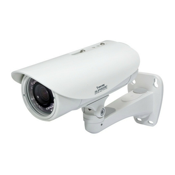
Page 4: Physical Description
Physical Description Light Sensor Lens IR LEDs Focus Controller Reset Button Zoom Controller General I/O Terminal Block SD/SDHC Card Slot General I/O Terminal Block AC 24V + AC 24V - Gb Ethernet RJ45 Plug Power Cord Socket EN-3... -
Page 5: Hardware Installation
Hardware Installation 1. Attach the alignment sticker to the wall. Drill three holes into the wall. Then hammer the supplied plastic anchors into the holes and secure the plate with supplied screws. 2. Feed the cables through the front opening of the wall mount bracket. (If you want to use external devices such as sensors and alarms, please refer to the assembling steps on the next page.) 3. -
Page 6: Waterproof Connector
Waterproof Connector Components of the Waterproof Connector Pin Definition Rubber (A) Power +12V Digital Output Screw Nut (B) Digital Input Seal (C) Ground Seals (D) RS485 + Housing (E) RS485 - Ground Sealing Nut (F) Audio Input Ground Audio Output Assembling Steps 1. - Page 7 IMPORTANT: Although the camera and the cable gland on the camera's end are waterproof, the cable molding at the other end is not waterproof. Measures should be taken to prevent water from leaking in through the cable-end molding, such as the use of expanding foam sealant, putties, and so on. Note that the cable gland on the camera should also be securely fastened to attain its waterproof functionality.
-
Page 8: Network Deployment
Network Deployment Power over Ethernet (PoE) When using a PoE-enabled switch The Network Camera is PoE-compliant, allowing transmission of power and data via a single Ethernet cable. Follow the below illustration to connect the Network Camera to a PoE-enabled switch via Ethernet cable. RJ45 Female/ Female Coupler PoE Switch... -
Page 9: Assigning An Ip Address
"Next" button to continue the program. Installation Wizard 2 3. The program will search for VIVOTEK Video Receivers, Video Servers, and Network Cameras on the same LAN. 4. After a brief search, the main installer window will pop up. Double-click on the MAC address that matches the one printed on the camera label or the S/N number on the package box label to open a browser management session with the Network Camera. -
Page 10: Ready To Use
Ready to Use 1. A browser session with the Network Camera should prompt as shown below. 2. You should be able to see live video from your camera. You may also install the 32-channel recording software from the software CD in a deployment consisting of multiple cameras. - Page 11 5. Tighten the lens cover. 6. Replace the moisture absorber with a new one if you open the back cover during the installation procedure. IMPORTANT: Please tear down the aluminum foil vacuum bag and take out the moisture absorber, then attach the absorber with the supplied double-sided tape.