
Related Manuals for Bowflex Blaze


Summary of Contents for Bowflex Blaze
-
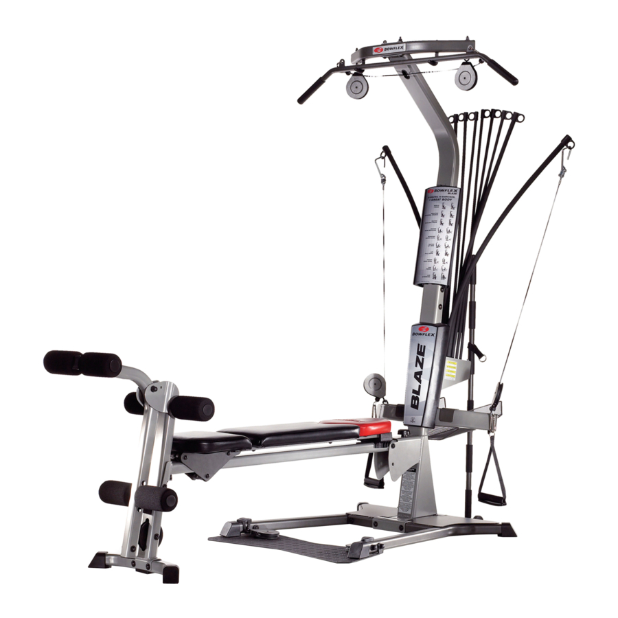
Page 1: Assembly Manual
The Bowflex Blaze ™ ® Home Gym Assembly Manual ��������������� PN 001-6903 Rev A (4/2006) -
Page 2: Table Of Contents
Table of Contents Safety Precautions Get to Know Your Machine Basic Assembly Principles Parts List Hardware List Accessory List Hardware Guide Tools You Will Need Assembly Guide... -
Page 3: Safety Precautions
Representative at (800) 628-8458 . do not use or allow others to use the Bowflex® • Read the owner’s manual and follow it carefully Blaze™ home gym if they weigh in excess of 300 before using the machine. pounds (136 kg). •... -
Page 5: Get To Know Your Machine
3. When attaching two pieces, gently lift and look through the bolt holes to help guide the bolt through the holes. 4. As a general rule, and for all bolts and nuts on your Bowflex® Blaze™ home gym, turn bolts or nuts toward the right to tighten and left to loosen. -
Page 6: Hardware Guide
Tools You Will Need You will need the following tools to complete the assembly of your Bowflex® Blaze™ home gym. If you don’t have these tools, you can find them at any hardware or department store for a reasonable price. - Page 7 Step 1 - Attach the Lower Lat Tower to the Base Platform Locate the following items: • Item #1 - Lower Lat Tower • Item #2 - Base Platform • Item #H - (4) 3/8" X 3" Button Head Screws •...
- Page 8 Step 3 - Attach the Squat Platform to the Main Assembly Locate the following items: • From Step 2 - Base Platform/Lat Tower (Main) Assembly • Item #5 - Squat Platform • Item #I - (2) 3/8" X 3 1/4" Button Head Screws •...
-
Page 9: Assembly Guide
Assembly Guide Step 4 - Attach the Chest Bar with Pulleys to the Figure 4 Main Assembly Locate the following items: Chest Bar Brackets • From Step 3 - Main Assembly • Item #6 - Chest Bar w/ Pulleys - Do not unwrap cables! •... - Page 10 Step 6 - Attach the Seat Rail to the Seat Assembly Locate the following items: • From Step 5 - Seat Pad/Seat Bracket Assembly • Item #9 - Seat Rail Undo the twist ties from the Rail Pivot Bushings and remove the Bushings.
- Page 11 Step 8 - Attach the Rear Leg to the Seat Rail Figure 8 Locate the following items: • From Step 6 - Seat Rail Assembly • From Step 7 - Rear Leg Assembly • Item #J - (1) 3/8" X 4 1/4" Button Head Screw •...
- Page 12 Step 9 - Attach the Seat Rail to the Main Assembly Figure 9 Locate the following items: • From Step 4 - Main Assembly Main Assembly • From Step 8 - Seat Rail Assembly • Item #12 - Seat Rail Knob •...
- Page 13 Assembly Guide Step 10 - Attach the Leg Extension Pivot Tube Figure 10a Bracket Locate the following items: • Item #13 - Leg Extension Pivot Tube • From Step 9 - Main Assembly • Item #30 - Lock Out Pin •...
- Page 14 Assembly Guide Figure 12...
- Page 15 Assembly Guide Figure 13 Step 13 - Assemble the Leg Extension Seat Locate the following items: • Item #19 - Leg Extension Seat Pad • Item #21 - Leg Extension Seat Support Tube • Item #C - (4) 5/16" X 3/4" Button Head Screws •...
- Page 16 Assembly Guide Step 14 - Attach the Leg Extension Seat to the Main Figure 14 Assembly Leg Extension Seat Locate the following items: Back Edge • From Step 13 - Leg Extension Seat Assembly • From Step 12 - Main Assembly The Leg Extension Seat Assembly is removable, and can be Support Tube attached to the Rear Leg Assembly easily by placing the Rail...
- Page 17 Assembly Guide Figure 16 Step 16 - Attach the Upper Lat Tower to the Lower Locate the following items: • From Step 15 - Upper Lat Tower Assembly • From Step 14 - Main Assembly • Item #E - (6) 3/8" X 3/4" Button Head Screw •...
- Page 18 Figure 19...
- Page 19 Figure 20...
- Page 20 Bench into the half hinge on the seat. To remove the Bench, lift up on the long portion and pull away from Seat. Steps 23 through 26 illustrate how to route and connect the Cables to your new Bowflex Blaze Home Gym.
- Page 21 Assembly Guide Step 24 - Attach the Accessory Basket Locate the following items: • Item #CC - Accessory Basket Place the hooks on the Accessory Basket over the the Chest Bar as shown. Figure 25 - Rod Cables Step 25 - Route the Rod Cables Locate the following items: •...
- Page 22 Step 26 - Route the Lat Cables Locate the following items: • Item #S- (2) Hand Grips • Item #R- (1) Bent lat Bar (optional) • Item #Z- (2) Lat Cableswith (2) Snap Hooks (attached) Unwrap the Lat Cables with Snap Hooks from both pulleys on the Lat Cross Bar.
- Page 23 1-800-NAUTILUS (628-8458) for assistance. ©2006 Nautilus Inc. All rights reserved. 16400 SE Nautilus Drive, Vancouver, Washington, USA 98683. Bowflex, Blaze, Power Rod and the Bowflex and Nautilus logos are either registered trademarks or trademarks of Nautilus, Inc.