Table of Contents
Advertisement
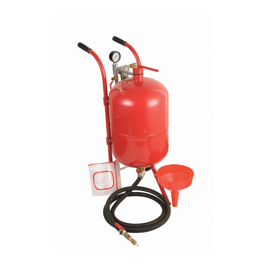
40 LB. PRESSURIZED
SANDBLASTER
Assembly and OPERATING INSTRUCTIONS
3491 Mission Oaks Blvd. / Camarillo, CA 93011
Copyright © 1997 by Harbor Freight Tools
. All rights reserved.
®
No portion of this manual or any artwork contained herein may be reproduced in any
shape or form without the express written consent of Harbor Freight Tools.
For technical questions and replacement parts, please call 1-800-444-3353.
Advertisement
Table of Contents

Related Manuals for Central Pneumatic 34202


Summary of Contents for Central Pneumatic 34202
- Page 1 . All rights reserved. ® No portion of this manual or any artwork contained herein may be reproduced in any shape or form without the express written consent of Harbor Freight Tools. For technical questions and replacement parts, please call 1-800-444-3353.
-
Page 2: Specifications
Wear a full face shield if you are producing metal filings or wood chips. Wear and ANSI approved dust mask or respirator when working around metal, wood, and chemical dusts and mists. Page #2 -- SKU 34202 SPECIFICATIONS SAVE THIS MANUAL SAFETY WARNING &... - Page 3 RELEASE THE AIR PRESSURE OF THE TANK BEFORE OPENING. Open the air supply valve and the nozzle to release pressure. Make sure pressure gauge reads “0” before opening. Page #3 -- SKU 34202...
- Page 4 When unpacking, sort all pieces and check according to the parts list and diagram to make sure all parts are included. All sizes listed are approximate. All Valve Assemblies are individually packed. If any parts are missing or broken, please call Harbor Freight Tools at the number on the cover of this manual.
- Page 5 Step4: Attach the 3/8" end of the NIPPLE CONNECTOR to the other end of the BRASS THROTTLING VALVE. Step5: Attach the JOINT PIPE to the lower side hole of the INTAKE MANIFOLD. Page #5 -- SKU 34202 ASSEMBLY Pressure Gauge...
- Page 6 Step3: On the top of the WATER TRAP is an arrow. Attach the BRASS AIR SUPPLY VALVE to the NIPPLE CONNECTOR that the arrow is facing away from. Step4: Attach the MALE/FEMALE ADAPTER to the BRASS AIR SUPPLY VALVE. Page #6 -- SKU 34202 Figure 2 — Water Trap Assembly Nipple Connector...
- Page 7 NIPPLE CONNECTOR and the NOZZLE. The flat end of the GASKET should face the NIPPLE CONNECTOR. Step4: Attach the other end of the NIPPLE CONNECTOR to one side of the STEEL SHUT OFF VALVE. Page #7 -- SKU 34202 Tank (#1) Nipple...
- Page 8 ADAPTER (#25). Tighten the HOSE CLAMP very securely. Step4: Slide the other end of the SAND HOSE onto the Sand Control Valve Assembly’s SAND OUTLET MANIFOLD (#22). Tighten the HOSE CLAMP very securely. Page #8 -- SKU 34202 Hose Clamp (#23)
- Page 9 Step6: Attach the female end of the AIR HOSE to the BRASS THROTTLING VALVE’S (#18A) NIPPLE CONNECTOR (#16). Step7: Attach the male end of the AIR HOSE to the SAND OUTLET MANIFOLD(#22), underneath the TANK. Page #9 -- SKU 34202 Air Cap (#12) Gasket...
- Page 10 Step3: Attach both HANDLE BARS to the TANK (#1) using the four SCREWS, NUTS, and WASHERS. The HANDLE BARS must curve back and the holes in their bottoms must be parallel to each other. The WASHERS go between the NUTS and the TANK. Page #10 -- SKU 34202 Right Handle (#6-R) Figure 7 —...
- Page 11 Step 4: Slide the AXLE through the hole in the bottom of the two HANDLE BARS (#6). Step 5: Attach the other WHEEL to the AXLE using the remaining COTTER PINS. Safety Valve Step 1: Screw the SAFETY VALVE (#10) into the hole in the top of the TANK (#1). Page #11 -- SKU 34202...
- Page 12 Step 8: Close the NOZZLE SHUT OFF VALVE and open the AIR SUPPLY VALVE. Step 9: Check for leaks at the TANK CAP as pressurization begins. Step 10: Open the NOZZLE SHUT OFF VALVE to begin blasting. Page #12 -- SKU 34202 OPERATIONS Always wear your hood, dust...
- Page 13 3/8" Nipple Connector Water Trap 3/8" Brass Air Supply Valve 1 3/8" Brass Throttling Valve * Note: Left Handle is #6-L, Right Handle is #6-R. Page #13 -- SKU 34202 MAINTENANCE PARTS LIST Item# Description 3/8" Steel Sand Control Valve 3/8"...
- Page 14 Page #14 -- SKU 34202 PARTS DRAWING 27A-D...