Table of Contents
Advertisement
GARAGE DOOR OPENER
For Residential Use Only
Owner's Manual
I
Please read this manual and the enclosed safety materials carefully!
I
Fasten the manual near the garage door after installation.
I
The door WILL NOT CLOSE unless the Protector System
properly aligned.
I
Periodic checks of the opener are required to ensure safe operation.
I
The model number label is located on the front panel of your opener.
Model M100 - 1/2HP
Model M50 - 1/3HP
The Chamberlain Group, Inc.
845 Larch Avenue
Elmhurst, Illinois 60126-1196
www.chamberlaingroup.com
®
is connected and
®
Advertisement
Table of Contents

Related Manuals for Chamberlain M50 - 1/3HP


Summary of Contents for Chamberlain M50 - 1/3HP
- Page 1 ® GARAGE DOOR OPENER For Residential Use Only Model M100 - 1/2HP Model M50 - 1/3HP Owner’s Manual Please read this manual and the enclosed safety materials carefully! Fasten the manual near the garage door after installation. The door WILL NOT CLOSE unless the Protector System ®...
-
Page 2: Table Of Contents
TABLE OF CONTENTS Introduction Pages 2-5 Adjustment Pages 24-26 Safety symbol and signal word review......2 Adjust the travel limits ..........24 Preparing your garage door ........3 Adjust the force ............25 Tools needed ...............3 Test the safety reversal system.........26 Planning ..............4 Test the Protector System ®... -
Page 3: Preparing Your Garage Door
Preparing your garage door WARNING Before you begin: To prevent possible SERIOUS INJURY OR DEATH: • Disable locks. • ALWAYS call a trained door systems technician if CAUTION • Remove any ropes connected to garage door. garage door binds, sticks, or is out of balance. An unbalanced garage door may not reverse when •... -
Page 4: Planning
Planning Identify the type and height of your garage door. Survey your garage area to see if any of the conditions below apply to your installation. Additional materials may be required. You may find it helpful to refer back to this page and the accompanying illustrations as you proceed with the installation of your opener. -
Page 5: Carton Inventory
Carton Inventory Your garage door opener is packaged in two cartons purchased. If anything is missing, carefully check the which contain the motor unit and all parts illustrated packing material. Parts may be stuck in the foam. below. Accessories will depend on the model Hardware for installation is also listed below. -
Page 6: Assembly Pages
WARNING CAUTION ASSEMBLY STEP 1 Attach the T-Rail to the Motor Unit To avoid serious damage to opener, ONLY use bolts mounted in top of motor unit. To avoid installation difficulties, do not run the garage door opener until instructed to do so. •... -
Page 7: Tighten The Chain
ASSEMBLY STEP 3 Lock Washer Outer Nut Tighten the Chain Inner Nut To Tighten Outer Nut • Spin the inner nut and lock washer down the threaded shaft, away from the trolley. To Tighten Inner Nut • To tighten the chain, turn outer nut in the direction shown. -
Page 8: Determine The Header Bracket Location
INSTALLATION STEP 1 Finished Determine the Header Bracket Vertical Ceiling Centerline Location Header Structural Wall Supports WARNING WARNING To prevent possible SERIOUS INJURY or DEATH: • Header bracket MUST be RIGIDLY fastened to CAUTION WARNING structural support on header wall or ceiling, otherwise garage door might not reverse when required. - Page 9 ONE-PIECE DOOR WITHOUT TRACK Unfinished 1. Close the door and mark the inside vertical Ceiling centerline of your garage door. Extend the line onto the header wall above door, as shown. Structural Supports Header Wall If headroom clearance is minimal, you can install Vertical Centerline the header bracket on the ceiling.
-
Page 10: Install The Header Bracket
INSTALLATION STEP 2 Install the Header Bracket Wall Mounting Holes You can attach the header bracket either to the wall above the garage door, or to the ceiling. Follow the CEILING MOUNT ONLY The nail hole is for instructions which will work best for your particular positioning only. -
Page 11: Attach The T-Rail To The Header Bracket
INSTALLATION STEP 3 Attach the T-Rail to the Header Bracket • Position the opener on the garage floor below the header bracket. Use packing material as a protective base. NOTE: If the door spring is in the Header Wall way you’ll need help. Have someone hold the Header opener securely on a temporary support to allow Bracket... -
Page 12: Position The Opener
WARNING CAUTION INSTALLATION STEP 4 Position the Opener To prevent damage to garage door, rest garage door opener rail on 2x4 placed on top section of door. Follow instructions which apply to your door type as illustrated. SECTIONAL DOOR OR ONE-PIECE DOOR WITH TRACK A 2x4 laid flat is convenient for setting an ideal door- to-rail distance. -
Page 13: Hang The Opener
WARNING INSTALLATION STEP 5 Hang the Opener To avoid possible SERIOUS INJURY from a falling garage door opener, fasten it SECURELY to structural CAUTION Two representative installations are shown. Yours supports of the garage. Concrete anchors MUST be used may be different. Hanging brackets should be angled if installing any brackets into masonry. -
Page 14: Install The Door Control
WARNING WARNING CAUTION WARNING INSTALLATION STEP 6 Install the Door Control To prevent possible SERIOUS INJURY or DEATH from electrocution: Locate door control within sight of the door at a • Be sure power is not connected BEFORE installing door minimum height of 5 feet where small children control. -
Page 15: Install The Light(S) And Lens(Es)
INSTALLATION STEP 7 Figure 1 Install the Light(s) and Lens(es) Lens Guide INSTALL THE LIGHTS • Install a 75 watt maximum light bulb in each socket. Lens The light(s) will turn ON and remain lit for approximately 4-1/2 minutes when power is connected. -
Page 16: Electrical Requirements
WARNING WARNING INSTALLATION STEP 9 Electrical Requirements To prevent possible SERIOUS INJURY or DEATH from electrocution or fire: CAUTION WARNING To avoid installation difficulties, do not run the • Be sure power is not connected to the opener, and opener at this time. disconnect power to circuit BEFORE removing cover to To reduce the risk of electric shock, your garage door establish permanent wiring connection. -
Page 17: Install The Protector System
WARNING INSTALLATION STEP 10 Install The Protector System ® • Be sure power is not connected to the garage door opener BEFORE installing the safety reversing sensor. CAUTION The safety reversing sensor must be connected • To prevent SERIOUS INJURY or DEATH from a closing and aligned correctly before the garage door garage door: opener will move in the down direction. - Page 18 INSTALLING THE BRACKETS Figure 1 Be sure power to the opener is disconnected. DOOR TRACK MOUNT (RIGHT SIDE) Install and align the brackets so the sensors will face each other across the garage door, with the beam no Door higher than 6" above the floor. They may be installed Track in one of three ways, as follows.
-
Page 19: Mounting And Wiring The Safety Sensors
MOUNTING AND WIRING THE SAFETY SENSORS Figure 4 • Slide a 1/4"-20x1/2" carriage bolt head into the slot Wing nut on each sensor. Use wing nuts to fasten sensors to brackets, with lenses pointing toward each other across the door. Be sure the lens is not obstructed by a bracket extension. -
Page 20: Fasten The Door Bracket
WARNING CAUTION INSTALLATION STEP 11 Fasten the Door Bracket To prevent damage to garage door, reinforce inside of door with angle iron both vertically and horizontally. Follow instructions which apply to your door type as illustrated below or on the following page. A horizontal reinforcement brace should be long Header enough to be secured to two or three vertical... - Page 21 ONE-PIECE DOORS Please read and comply with the warnings and reinforcement instructions on the previous page. They apply to one-piece doors also. • Center the door bracket on the top of the door, in line with the header bracket as shown. Mark either the left and right, or the top and bottom holes.
-
Page 22: Connect Door Arm To Trolley
INSTALLATION STEP 12 Inner Trolley Connect Door Arm to Trolley Outer Trolley Follow instructions which apply to your door type as illustrated below and on the following page. Clevis Pin SECTIONAL DOORS ONLY 5/16"x1" Ring • Make sure garage door is fully closed. Pull the Fastener emergency release handle to disconnect the outer trolley from the inner trolley. -
Page 23: Connect The Door Arm To The Trolley
ALL ONE-PIECE DOORS Door Ring Bracket 1. Assemble the door arm: Fastener Nuts Lock • Fasten the straight and curved door arm sections 5/16"-18 Washers together to the longest possible length (with a 2 5/16" or 3 hole overlap). Clevis Pin Straight 5/16"x1-1/4"... -
Page 24: Adjustment Pages
WARNING ADJUSTMENT STEP 1 Adjust the UP and DOWN Travel Without a properly installed safety reversal system, Limits persons (particularly small children) could be CAUTION SERIOUSLY INJURED or KILLED by a closing garage Limit adjustment settings regulate the points at which door. -
Page 25: Adjust The Force
WARNING ADJUSTMENT STEP 2 Adjust the Force Without a properly installed safety reversal system, persons (particularly small children) could be CAUTION Force adjustment controls are located on the back SERIOUSLY INJURED or KILLED by a closing garage panel of the motor unit. Force adjustment settings door. -
Page 26: Test The Safety Reversal System
WARNING ADJUSTMENT STEP 3 Test the Safety Reversal System Without a properly installed safety reversal system, persons (particularly small children) could be CAUTION SERIOUSLY INJURED or KILLED by a closing garage TEST door. • With the door fully open, place a one-inch board •... -
Page 27: Operation Pages
OPERATION IMPORTANT SAFETY INSTRUCTIONS WARNING To reduce the risk of severe injury or death: CAUTION 1. READ AND FOLLOW ALL WARNINGS AND 8. If one control (force or travel limits) is adjusted, the INSTRUCTIONS. other control may also need adjustment. 2. -
Page 28: Using The Wall-Mounted Door Control
Using the Wall-Mounted B) To operate one door using all three buttons on the hand-held remote: Door Control You may program the remote to Open Press the push bar/button Close Push open the door with the large button, Stop to open or close the door. close it with the middle button, and stop the Press again to reverse the Push... -
Page 29: Care Of Your Garage Door Opener
Care of Your Opener Having a Problem? 1. The opener doesn't operate from either the LIMIT AND FORCE ADJUSTMENTS: Door Control or the remote control: Weather conditions may cause • Does the opener have electric power? Plug a lamp some minor changes in door into the outlet. -
Page 30: Operation
Having a Problem? (Continued) 11. The door reverses for no apparent reason and opener lights blink for 5 seconds after 6. The garage door opens and closes by itself: reversing: • Be sure that all remote control push buttons are •... -
Page 31: Programming Pages
PROGRAMMING Your garage door opener has already been programmed at the factory to operate with your hand-held remote control. The door will open and close when you press the large push button. Below are instructions for programming your opener to operate with additional Security remote controls. -
Page 32: To Add Or Change A Keyless Entry Pin
To Add or Change a Keyless Entry PIN NOTE: Your new Keyless Entry must be programmed to operate your garage door opener. USING THE “LEARN” BUTTON USING THE MULTI-FUNCTION DOOR CONTROL 1. Press and release the “learn” NOTE: This method requires two people if the Keyless button on motor unit. -
Page 33: Repair Parts Pages
REPAIR PARTS Rail Assembly Parts PART DESCRIPTION 4A1008 Master link kit 41A4813 Chain pulley bracket 41A3489 Complete trolley assembly 183B99 One-piece T-rail 41D3484 Full chain assembly 83A11-2 Rail grease Installation Parts KEY PART DESCRIPTION 41A5273-13 Multi-function door control panel 41A4166 Lighted door control button 10A20 3V2032 Lithium battery... -
Page 34: Motor Unit Assembly Parts
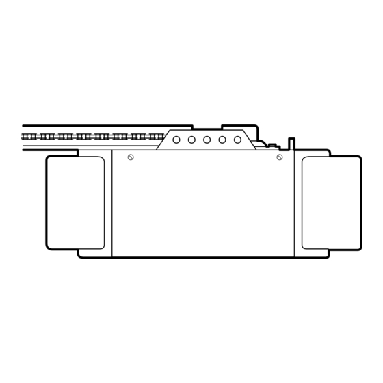
Motor Unit Assembly Parts (M50) (M100) (M100) (M100) (M100) (M50) (Down) LIMIT SWITCH ASSY. Contact Brown Wire Grey Wire Drive Gear Center Limit (Up) Yellow Contact Contact Wire PART PART DESCRIPTION DESCRIPTION 41A3583-19 Cover (M100) 31D380 Sprocket cover 41A3583-20 Cover (M50) 41C4220A Gear and sprocket assembly 41A2818... -
Page 35: Accessories
ACCESSORIES 1702LM 971AC SECURITY Single-Function Outside Quick Release: Remote Control: Required for a garage with NO access Includes visor clip. door. Enables homeowner to open garage door manually from outside by disengaging trolley. SECURITY 2-Channel 972AC 59LM Outside Keylock: Remote Control: Opens the garage door Includes visor clip. -
Page 36: Repair Parts And Service
ACCESS MASTER GARAGE DOOR OPENER ONE-YEAR LIMITED WARRANTY Chamberlain/Access Master (“Seller”) warrants, to the first retail purchaser of this product, for the residence in which this product is originally installed, that it will be free from any defect in materials and/or workmanship for a period of one year from the date of purchase.