Advertisement
Quick Links
For Heavy
Median
{FAM
Instructions
Duty {/:AS
Models)
and
Models)
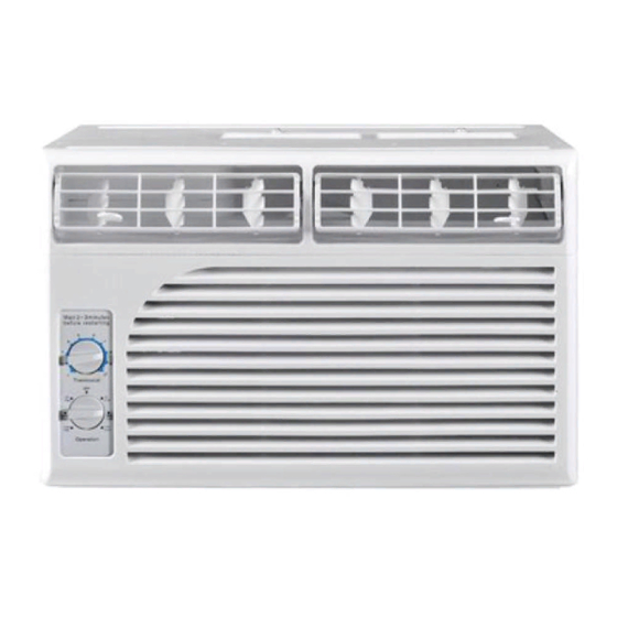
Air Conditioners
Please read ALL instructions be_hre installing.Two
people are
recommended
to install this prodaetdf
a new electrical outlet
is reqaired,have
the outlet installed by a qaalified electrician
be_re
installing
anit. See#5 in Prdiminary
lnstraetions
_bllowing.
Preitiminary
Do the _bHowiog be_bre startiog to iostall aoR.See illustrations
bdow.
Check dimensions of your unit to determine
model type:
Heavy du D' (FAS)
Median
(FAM)
Unit Height:
18.5/8"
17.5/8"
Unit Width:
26 1/.
23 1/.
Min. Window Opening:
19"
18 72"
Min. Window Width:
31"
26 1/,,
Max. Window Width:
43"
40 1/2"
1° Check window opening size = the mounting parts furnished
with this air conditioner arc made to install in a wooden
sill double-hung
window.The
standard parts are for
window dimensions
listed aboveX)pen
sash to a minimum
of i9"(483mm).
(FIG. i)
2.
Cheek condition
of window = all wood parts of window
must be in good shape and able to firmly hold the needed
sorer s.If not, make repairs before installing
uniL
FIG. 1
SASH
1/2" MIN
T
19" MIN
1
STORM
WINDOW
FRAME
OR
OTHER OBSTRUCTION
SIDE RETAINER
/
BRACKET
3_
Check your storm windows
= if your storm window
*?ame does not allow the clearance required, correct by
adding a piece of wood as shown in FIG.2, or by removing
storm window while room air conditioner is being installed.
(continued)
FIG. 2
SASH
t
19" MIN
1/2" MIN
i 1 1/2" MIN
I
_
ENTIRE
STOOL,
FASTEN
STORM WINDOW
FRAME OR
WITH TWO NAILS OR
OTHER OBSTRUCTION
SCREWS.
P/N
66121623
Advertisement

Related Manuals for Crosley CAE18ESR1


Summary of Contents for Crosley CAE18ESR1
- Page 1 Instructions For Heavy Duty {/:AS Models) Median {FAM Models) Air Conditioners Please read ALL instructions be_hre installing.Two people are recommended to install this prodaetdf a new electrical outlet is reqaired,have the outlet installed by a qaalified electrician be_re installing anit. See#5 in Prdiminary lnstraetions _bllowing.
- Page 2 4. CHECK FOR ANYTHING THAT COULD BLOCK Too s Nequired AIRFLOW- check area outside of window for things such as shrubs, trees, or awnings. Inside, be sure a large flat blade screwdriver flu_nimre, drapes, or blinds will not stop proper air flow. tape uleasure adjustable...
- Page 3 lnstatm Top Angl÷ Remove Chassis and Side Bracket 1. 1hill down ftont panel axt remove filter. (See FIG. !). Attach tbam gasket to top angle above holes as 2. Lift ftont upwards and place to one side. shown in FIG. 6. 2.
- Page 4 Rnstal! Support 3. Insel_ top and bottom legs of window filler panel flmne into chmmel in the to angle and bottom rail. Do both sides. 1. Hold each support bracket flush against outside of sill, 4. Insert washer head locking screws (2) into holes in and tight to bottom of cabinet as shown below.
- Page 5 tnstam! Chassis into Extend Window Filler Cabinet and |nstall Front to Unit 1. Carefully raise window to expose filler panel locking 1, Lift air c(mditiooer al_d carefully slide ioto cabioet screws. Loosel_ screws so filler pal_els slide easily. leaving 6" protruding. 2, _DO _ot push oft cootrols OR firmed coils.
-
Page 6: Installation
Thru-The-Wall Installation NOTE: Consult local building codes prior to installation, Carefully measure and cut an opening with the following or a qualified carpenter. dimensions depending on your model. See FIGS. land 2. WIDTH "X" - inside model width plus twice the thickness Select Wall Location... - Page 7 NOTE: If wall thickmess is 8-1/2" or more, add alumimnn flashing over bottom of fimne opening to assure no water FIG°2 can enter area between inner and outer wall. 1"LONG WOOD SCREW Refer to Step 4 of Window Mounting _br assembly of support bmckets.A wooden strip nailed to the outside AL[JMINUIM FLASHING O_ER...
- Page 8 OPTIONAL:Cmllking andinstallation o f tfimoninterior wallmay bedone. Youcanbuywood Iiomyourlocal l umber orhardware supply. Ontheoutside, caulk openings around top and sides of cabinet, andallsides o f wood sleeve t otheopening. NOTE: See Step 7,Item3of Window Mounting Instructions lot bottom railseal location. Masen Construction 1.